Wai-Fah Chen.The Civil Engineering Handbook
Подождите немного. Документ загружается.

Theory and Analysis of Structures 47-21
m = 2j – r (47.20)
which must be satisfied if it is to be statically determinate internally. r is the least number of reaction
components required for external stability. If m exceeds (2j – r), then the excess members are called
redundant members, and the truss is said to be statically indeterminate.
For a statically determinate truss, member forces can be found by using the method of equilibrium.
The process requires repeated use of free-body diagrams from which individual member forces are
determined. The method of joints is a technique of truss analysis in which the member forces are
determined by the sequential isolation of joints — the unknown member forces at one joint are solved
and become known for the subsequent joints. The other method is known as method of sections, in which
equilibrium of a part of the truss is considered.
Method of Joints
An imaginary section may be completely passed around a joint in a truss. The joint has become a free
body in equilibrium under the forces applied to it. The equations SH = 0 and SV = 0 may be applied
to the joint to determine the unknown forces in members meeting there. It is evident that no more than
two unknowns can be determined at a joint with these two equations.
Example 47.3
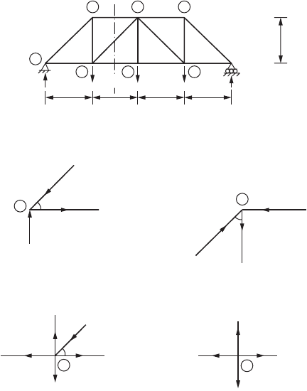
A truss shown in Fig. 47.19 is symmetrically loaded and is sufficient to solve half the truss by considering
joints 1–5. At joint 1, there are two unknown forces. Summation of the vertical components of all forces
at joint 1 gives
135 – F
12
sin45° = 0
which in turn gives the force in members 1 and 2, F
12
= 190 kN (compressive). Similarly, summation of
the horizontal components gives
F
13
– F
12
cos45° = 0
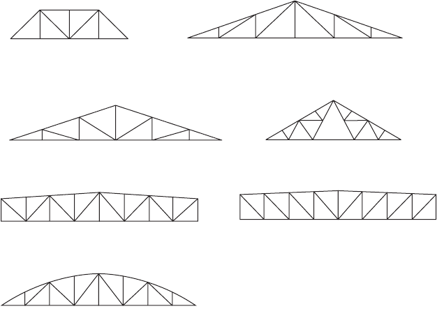
FIGURE 47.18 Typical planar trusses.
Bowstring truss
Pratt truss
Warren truss
Howe truss Fink truss
Warren truss
Pratt truss
© 2003 by CRC Press LLC
47-22 The Civil Engineering Handbook, Second Edition
Substituting for F
12
gives the force in member 1–3 as
F
13
= 135 kN (tensile)
Now, joint 2 is cut completely, and it is found that there are two unknown forces F
25
and F
23
. Summation
of the vertical components gives
F
12
cos45° – F
23
= 0
Therefore
F
23
= 135 kN (tensile)
Summation of the horizontal components gives
F
12
sin45°
– F
25
= 0
and hence
F
25
= 135 kN (compressive)
After solving for joints 1 and 2, one proceeds to take a section around joint 3 at which there are now
two unknown forces viz. F
34
and F
35
. Summation of the vertical components at joint 3 gives
F
23
– F
35
sin45°
– 90 = 0
Substituting for F
23
, one obtains F
35
= 63.6 kN (compressive). Summing the horizontal components and
substituting for F
13
one gets
FIGURE 47.19 Example of the method of joints, planar truss.
F
13
F
23
F
35
F
34
90 kN
45°
3
F
34
F
45
F
67
90 kN
4
F
23
F
25
F
12
45°
2
2
1
135 kN
F
13
45°
F
12
135 kN
1
A
3
4
90 kN
90 kN
90 kN
7
135 kN
5
6
6 m 6 m 6 m 6 m
6 m
A
© 2003 by CRC Press LLC
Theory and Analysis of Structures 47-23
–135 – 45 + F
34
= 0
Therefore,
F
34
= 180 kN (tensile)
The next joint involving two unknowns is joint 4. When we consider a section around it, the summation
of the vertical components at joint 4 gives
F
45
= 90 kN (tensile)
Now, the forces in all the members on the left half of the truss are known, and by symmetry the forces
in the remaining members can be determined. The forces in all the members of a truss can also be
determined by using the method of sections.
Method of Sections
In this method, an imaginary cutting line called section is drawn
through a stable and determinate truss. Thus, a section divides the
truss into two separate parts. Since the entire truss is in equilibrium,
any part of it must also be in equilibrium. Either of the two parts of
the truss can be considered, and the three equations of equilibrium
SF
x
= 0, SF
y
= 0, and SM = 0 can be applied to solve for member
forces.
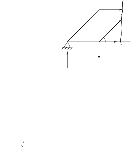
Example 47.3 above (Fig. 47.20) is once again considered. To cal-
culate the force in members 3–5, F
35
, section AA should be run to
cut members 3–5 as shown in the figure. It is required only to con-
sider the equilibrium of one of the two parts of the truss. In this case,
the portion of the truss on the left of the section is considered. The
left portion of the truss as shown in Fig. 47.20 is in equilibrium under
the action of the forces viz. the external and internal forces. Consid-
ering the equilibrium of forces in the vertical direction, one can
obtain
135 – 90 + F
35
sin45˚ = 0
Therefore, F
35
is obtained as
The negative sign indicates that the member force is compressive. The other member forces cut by the
section can be obtained by considering the other equilibrium equations viz. SM = 0. More sections can
be taken in the same way to solve for other member forces in the truss. The most important advantage
of this method is that one can obtain the required member force without solving for the other member
forces.
Compound Trusses
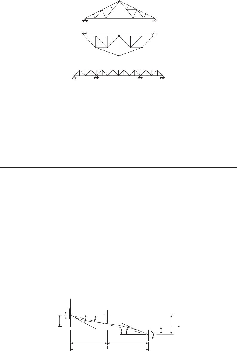
A compound truss is formed by interconnecting two or more simple trusses. Examples of compound
trusses are shown in Fig. 47.21. A typical compound roof truss is shown in Fig. 47.21a in which two
simple trusses are interconnected by means of a single member and a common joint. The compound
truss shown in Fig. 47.21b is commonly used in bridge construction, and in this case, three members
are used to interconnect two simple trusses at a common joint. There are three simple trusses intercon-
nected at their common joints, as shown in Fig. 47.21c.
FIGURE 47.20 Example of the
method of sections, planar truss.
A
A
90 kN
135 kN
F
35
45°
FkN
35
=-45 2
© 2003 by CRC Press LLC
47-24 The Civil Engineering Handbook, Second Edition
The method of sections may be used to determine the member forces in the interconnecting members
of compound trusses, similar to those shown in Fig. 47.21a and b. However, in the case of a cantilevered
truss the middle simple truss is isolated as a free-body diagram to find its reactions. These reactions are
reversed and applied to the interconnecting joints of the other two simple trusses. After the intercon-
necting forces between the simple trusses are found, the simple trusses are analyzed by the method of
joints or the method of sections.
47.4 Frames
Frames are statically indeterminate in general; special methods are required for their analysis. Slope
deflection and moment distribution methods are two such methods commonly employed. Slope deflec-
tion is a method that takes into account the flexural displacements such as rotations and deflections and
involves solutions of simultaneous equations. Moment distribution, on the other hand, involves successive
cycles of computation, each cycle drawing closer to the “exact” answers. The method is more labor
intensive but yields accuracy equivalent to that obtained from the “exact” methods.
Slope Deflection Method
This method is a special case of the stiffness method of analysis. It is a convenient method for performing
hand analysis of small structures.
Let us consider a prismatic frame member AB with undeformed position along the x axis deformed into
configuration p, as shown in Fig. 47.22. Moments at the ends of frame members are expressed in terms of
the rotations and deflections of the joints. It is assumed that the joints in a structure may rotate or deflect,
but the angles between the members meeting at a joint remain unchanged. The positive axes, along with
the positive member-end force components and displacement components, are shown in the figure.
FIGURE 47.21 Compound truss.
FIGURE 47.22 Deformed configuration of a beam.
(a) Compound roof truss
(b) Compound bridge truss
(c) Cantilevered construction
V
AB
∆
AB
ψ
AB
θ
A
ψ
AB
V
BA
M
BA
M
AB
y
A
y
B
y
A
P
ab
B
x
θ
B
© 2003 by CRC Press LLC

Theory and Analysis of Structures 47-25
The equations for end moments may be written as
(47.21)
in which M
FAB
and M
FBA
are fixed-end moments at supports A and B, respectively, due to the applied
load. y
AB
is the rotation as a result of the relative displacement between member ends A and B given as
(47.22)
where D
AB
is the relative deflection of the beam ends. y
A
and y
B
are the vertical displacements at ends A
and B. Fixed-end moments for some loading cases may be obtained from Fig. 47.8. The slope deflection
equations in Eq. (47.21) show that the moment at the end of a member is dependent on member
properties EI, length l, and displacement quantities. The fixed-end moments reflect the transverse loading
on the member.
Frame Analysis Using Slope Deflection Method
The slope deflection equations may be applied to statically indeterminate frames with or without side
sway. A frame may be subjected to side sway if the loads, member properties, and dimensions of the
frame are not symmetrical about the centerline. Application of the slope deflection method can be
illustrated with the following example.
Example 47.4
Consider the frame shown in Fig. 47.23 subjected to side sway D to the right of the frame. Equation (47.21)
can be applied to each of the members of the frame as follows:
Member AB:
q
A
= 0,
FIGURE 47.23 Example of the slope deflection method.
M
EI
M
M
EI
M
AB A B AB FAB
BA B A AB FBA
=+-
()
+
=+-
()
+
2
23
2
23
l
l
qq y
qq y
y
AB
AB A B
yy
==
+D
11
MM
M
EI
M
MM
AB A B FAB
BA B A FBA
FAB FBA
=+-
Ê
Ë
Á
ˆ
¯
˜
+
=+-
Ê
Ë
Á
ˆ
¯
˜
+
==
2EI
6
2
3
20
2
20
2
3
20
0
qq
qq
D
D
180 kN
EI − Same for
all members
3 m 6 m
6 m
9 m
BC
D
A
© 2003 by CRC Press LLC

47-26 The Civil Engineering Handbook, Second Edition
Hence
(47.23)
(47.24)
in which
Member BC:
Hence
(47.25)
(47.26)
Member CD:
q
D
= 0,
Hence
(47.27)
(47.28)
M
EI
AB B
=-
()
2
6
3qy
M
BA B
=-
()
2EI
20
23qy
y=
D
6
M
EI
M
MM
BC B C FBC
CB FCB
=+-¥
()
+
=+-¥
()
+
=-
¥¥
=-
=-
¥¥
=
2
9
230
9
180 3 6
9
240
18 3 6
9
120
2
2
qq
qq
2EI
230
M
ft-kips
M
0
ft-kips
CB
FBC
2
FCB
2
M
EI
BC B C
=+
()
-
2
9
2 240qq
M
CB C B
=+
()
+
2EI
289
9
qq
M
EI
M
M
EI
M
MM
CD C D FCD
DC D C FDC
FCD FDC
=+-
Ê
Ë
Á
ˆ
¯
˜
+
=+-
Ê
Ë
Á
ˆ
¯
˜
+
==
2
9
2
3
30
2
9
2
3
30
0
qq
qq
D
D
M
EI
CD C
=-¥
Ê
Ë
Á
ˆ
¯
˜
=-
()
2EI
3
C
9
2
1
6
2
9
22
q
yqy
M
EI
DC C
=-¥
Ê
Ë
Á
ˆ
¯
˜
=-
()
2EI
3
C
9
1
6
2
9
2
q
yqy
© 2003 by CRC Press LLC

Theory and Analysis of Structures 47-27
Considering moment equilibrium at joint B
SM
B
= M
BA
+ M
BC
= 0
Substituting for M
BA
and M
BC
, one obtains
or
(47.29)
Considering moment equilibrium at joint C
SM
C
= M
CB
+ M
CD
= 0
Substituting for M
CB
and M
CD
we get
or
(47.30)
For summation of base shears equal to zero, we have
SH = H
A
+ H
D
= 0
or
Substituting for M
AB
, M
BA
, M
CD
, and M
DC
and simplifying
(47.31)
Solution of Eqs. (47.29) to (47.31) results in
EI
10 2 9
9
240qqy
BC
+-
()
=
110
160
BC
29
2
qq
y+-=
EI
2EI
42
CB
9
120
qq
y+-
()
=-
BC
42
qq
y+-=-
540
EI
MM MM
AB BA CD DC
+
+
+
=
69
0
212700
BC
qq
y+-=
B
.
.
q
q
=
=
-
342 7
169 1
EI
EI
C
© 2003 by CRC Press LLC

47-28 The Civil Engineering Handbook, Second Edition
and
(47.32)
Substituting for q
B
, q
C
, and y from Eq. (47.32) into Eqs. (47.23) to (47.28) we get
M
AB
= 11.03 kNm
M
BA
= 125.3 kNm
M
BC
= –125.3 kNm
M
CB
= 121 kNm
M
CD
= –121 kNm
M
DC
= –83 kNm
Moment Distribution Method
The moment distribution method involves successive cycles of computation, each cycle drawing closer
to the “exact” answers. The calculations may be stopped after two or three cycles, giving a very good
approximate analysis, or they may be carried out to whatever degree of accuracy is desired. Moment
distribution remains the most important hand-calculation method for the analysis of continuous beams
and frames, and it may be solely used for the analysis of small structures. Unlike the slope deflection
method, this method does require the solution to simultaneous equations.
The terms constantly used in moment distribution are fixed-end moments, the unbalanced moment,
distributed moments, and carryover moments. When all of the joints of a structure are clamped to prevent
any joint rotation, the external loads produce certain moments at the ends of the members to which they
are applied. These moments are referred to as fixed-end moments. Initially the joints in a structure are
considered to be clamped. When the joint is released, it rotates if the sum of the fixed-end moments at
the joint is not zero. The difference between zero and the actual sum of the end moments is the unbalanced
moment. The unbalanced moment causes the joint to rotate. The rotation twists the ends of the members
at the joint and changes their moments. In other words, rotation of the joint is resisted by the members,
and resisting moments are built up in the members as they are twisted. Rotation continues until equi-
librium is reached — when the resisting moments equal the unbalanced moment — at which time the
sum of the moments at the joint is equal to zero. The moments developed in the members resisting
rotation are the distributed moments. The distributed moments in the ends of the member cause moments
in the other ends, which are assumed fixed; these are the carryover moments.
Sign Convention
The moments at the end of a member are assumed to be positive when they tend to rotate the member
clockwise about the joint. This implies that the resisting moment of the joint would be counterclockwise.
Accordingly, under a gravity loading condition the fixed-end moment at the left end is assumed as
counterclockwise (–ve) and at the right end as clockwise (+ve).
Fixed-End Moments
Fixed-end moments for several cases of loading may be found in Fig. 47.8. Application of moment
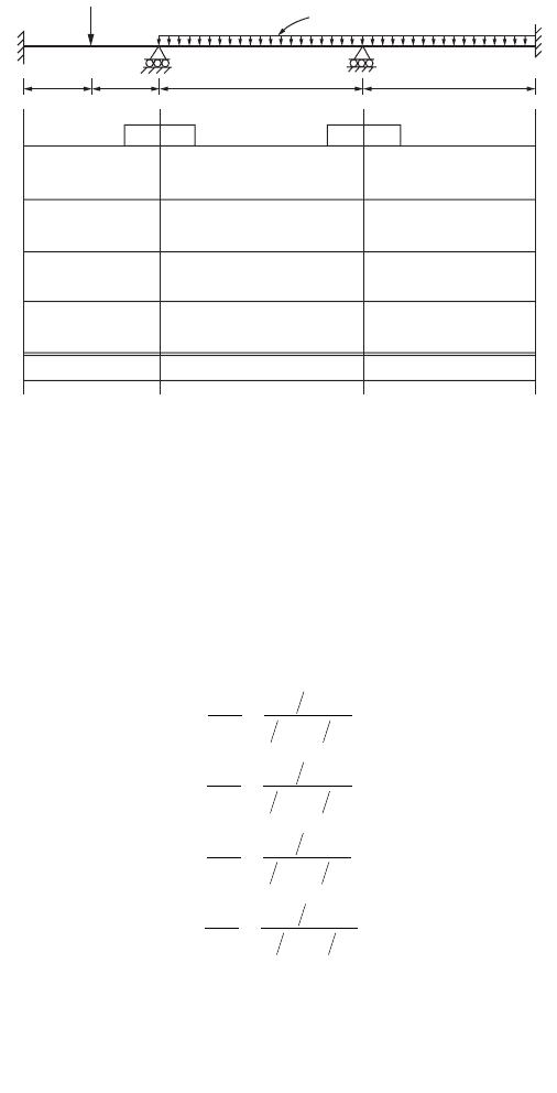
distribution may be explained with reference to a continuous beam example, as shown in Fig. 47.24.
Fixed-end moments are computed for each of the three spans. At joint B the unbalanced moment is
obtained and the clamp is removed. The joint rotates, thus distributing the unbalanced moment to the
B ends of spans BA and BC in proportion to their distribution factors. The values of these distributed
moments are carried over at one half rate to the other ends of the members. When equilibrium is reached,
y=
103 2.
EI
© 2003 by CRC Press LLC
Theory and Analysis of Structures 47-29
joint B is clamped in its new rotated position and joint C is released afterwards. Joint C rotates under
its unbalanced moment until it reaches equilibrium, the rotation causing distributed moments in the
C ends of members CB and CD and their resulting carryover moments. Joint C is now clamped and joint B
is released. This procedure is repeated again and again for joints B and C, the amount of unbalanced
moment quickly diminishing, until the release of a joint causes negligible rotation. This process is called
moment distribution.
The stiffness factors and distribution factors are computed as follows:
The fixed-end moments are
When a clockwise couple is applied near the end of a beam, a clockwise couple of half the magnitude
is set up at the far end of the beam. The ratio of the moments at the far and near ends is defined as the
carryover factor, 0.5 in the case of a straight prismatic member. The carryover factor was developed for
carrying over to fixed ends, but it is applicable to simply supported ends, which must have final moments
of zero. It can be shown that the beam simply supported at the far end is only three fourths as stiff as
the one that is fixed. If the stiffness factors for end spans that are simply supported are modified by three
fourths, the simple end is initially balanced to zero and no carryovers are made to the end afterward.
This simplifies the moment distribution process significantly.
FIGURE 47.24 Example of a continuous beam by moment distribution.
2 (Uniformly distributed)
90
EI EI EIBC
A
D
3
−50
30
3.1 −4.5 2.1 −5.5
+6.2
+2.7
+0.3 +0.2
+1.8
+4.2 −9.0
−0.9 −1.2
−11.0
−10.4 20 −12.7
50
60 40 −20.7 −25.3
−150 150 104−104
3
0.6 0.4
0.45
0.55
9 7.5
1.4
−15.5 119.2 −119.2 +142 −142 85.2
−0.5
−0.5−0.4
−0.60.9
DF
I
II
DF
I
II
DF
I
II
DF
I
II
BA
BC
CB
CD
=
Â
==
=
Â
==
=
Â
==
=
Â
==
BA
BC
CB
CD
K
K+
0.6
K
K+
0.4
K
K+
0.45
K
KI +
0.55
20
20 30
30
20 30
30
30 25
25
30 25
MM M
MM M
FAB FBC FCD
FBA FCB FDC
=- =- =-
== =
50 150 104
50 150 104
;;
;;
© 2003 by CRC Press LLC
47-30 The Civil Engineering Handbook, Second Edition
Moment Distribution for Frames
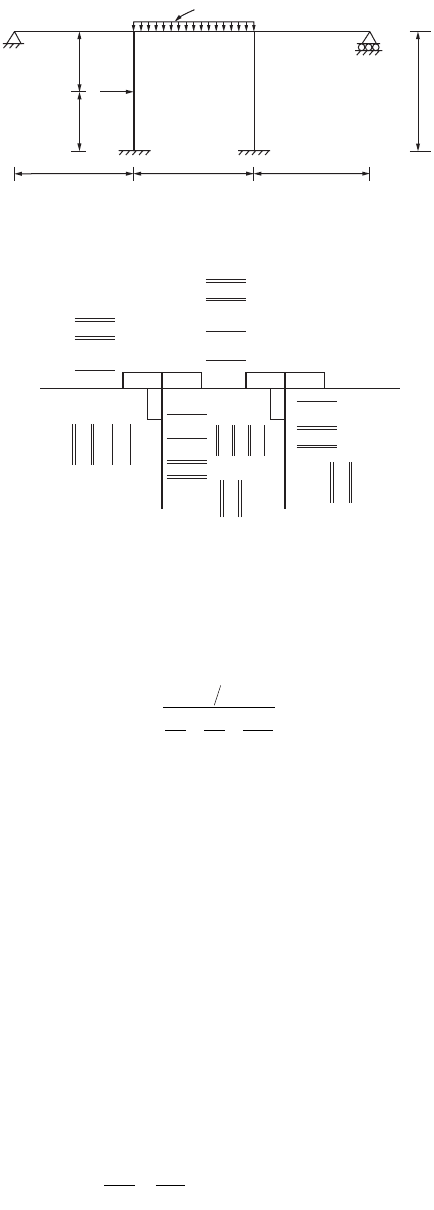
Moment distribution for frames without side sway is similar to that for continuous beams. The example
shown in Fig. 47.25 illustrates the applications of moment distribution for a frame without side sway.
Similarly,
Structural frames are usually subjected to side sway in one direction or the other, due to asymmetry
of the structure and eccentricity of loading. The sway deflections affect the moments, resulting in an
unbalanced moment. These moments could be obtained for the deflections computed and added to the
originally distributed fixed-end moments. The sway moments are distributed to columns. Should a frame
have columns all of the same length and the same stiffness, the side sway moments will be the same for
each column. However, should the columns have differing lengths or stiffnesses, this will not be the case.
The side sway moments should vary from column to column in proportion to their I/l
2
values.
The frame in Fig. 47.26 shows a frame subjected to sway. The process of obtaining the final moments
is illustrated for this frame.
The frame sways to the right, and the side sway moment can be assumed in the ratio
FIGURE 47.25 Example of a nonsway frame by moment distribution.
−53.92
− 0.79
− 3.13
A
EI EI
EI
2EI2EI
20
202020
10
10
20
BC
3
FE
D
+15.82
+80.86
−0.39
−25.0
+1.57
−1.57
−100.0
+ 12.5
+6.25
+100.0+12.5 0.25
81.64
+ 0.39
+ 6.25
+25.0
−50.0
+50.0 0.50
0.50
0.25 0.25 0.25
− 25.0
− 25.0
− 1.56
− 0.39
+0.20
+3.12
− 12.5
+ 3.13
− 0.79
+ 0.20
− 97.46
− 26.95
− 1.57
− 0.40
−50.0
−34.17
+12.5
+ 3.13
+ 0.20
− 26.97
DF
EI
BA
=
++
=
20
EI
20
EI
20
2EI
20
0.25
DF DF
MM
MM
BE BC
FBC FCB
FBE FEB
==
==
==-
05 025
0100 100
50 50
.; .
;
;
400
20
:
300
20
(or) 1 : 0.75
22
© 2003 by CRC Press LLC
