Wai-Fah Chen.The Civil Engineering Handbook
Подождите немного. Документ загружается.

48-84 The Civil Engineering Handbook, Second Edition
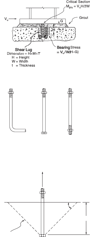
Anchor Bolts
Anchor bolts are provided to stabilize the column during erection and to prevent uplift for cases involving
large moments. Anchor bolts can be cast-in-place bolts or drilled-in bolts. The latter are placed after the
concrete is set and are not often used. Their design is governed by the manufacturer’s specifications.
Cast-in-place bolts are hooked bars, bolts, or threaded rods with nuts (Fig. 48.34) placed before the
concrete is set. Anchor rods and threaded rods shall conform to one of the following ASTM specifications:
A36/A36M, A193/A193M, A354, A572/A572M, A588/A588M, or F1554.
Of the three types of cast-in-place anchors shown in the figure, the hooked bars are recommended
for use only in axially loaded base plates. They are not normally relied upon to carry significant tensile
force. Bolts and threaded rods with nuts can be used for both axially loaded base plates or base plates
with moments. Threaded rods with nuts are used when the length and size required for the specific
design exceed those of standard-size bolts.
Failure of bolts or threaded rods with nuts occurs when the tensile capacities of the bolts are reached.
Failure is also considered to occur when a cone of concrete is pulled out from the pedestal. This cone
pullout type of failure is depicted schematically in Fig. 48.35. The failure cone is assumed to radiate out
from the bolt head or nut at an angle of 45°, with tensile failure occurring along the surface of the cone
FIGURE 48.33 Column base plate subjected to shear.
FIGURE 48.34 Base plate anchors.
FIGURE 48.35 Cone pullout failure.
Hooked Bar Bolt Threaded Rod
with Nut
Failure Cone
L
T
u
45°
© 2003 by CRC Press LLC
Design of Steel Structures 48-85
at an average stress of 4÷ f
c
¢, where f
c
¢ is the compressive strength of concrete in psi. The load that will
cause this cone pullout failure is given by the product of this average stress and the projected area of the
cone A
p
[Marsh and Burdette, 1985]. The design of anchor bolts is thus governed by the limit states of
tensile fracture of the anchors and cone pullout.
Limit State of Tensile Fracture
The area of the anchor should be such that
(48.129)
where A
g
= the required gross area of the anchor
F
u
= the minimum specified tensile strength
f
t
= 0.75 is the resistance factor for tensile fracture
Limit State of Cone Pullout
From Fig. 48.35, it is clear that the size of the cone is a function of the length of the anchor. Provided
that there are sufficient edge distance and spacing between adjacent anchors, the amount of tensile force
required to cause cone pullout failure increases with the embedded length of the anchor. This concept
can be used to determine the required embedded length of the anchor. Assuming that the failure cone
does not intersect with another failure cone or the edge of the pedestal, the required embedded length
can be calculated from the equation
(48.130)
where A
p
is the projected area of the failure cone, T
u
is the required bolt force in pounds, f
c
¢ is the
compressive strength of concrete in psi, and f
t
is the resistance factor (assumed to be equal to 0.75). If
failure cones from adjacent anchors overlap one another or intersect with the pedestal edge, the projected
area A
p
must be adjusted accordingly (see, for example, Marsh and Burdette [1985]).
The length calculated using the above equation should not be less than the recommended values given
by Shipp and Haninger [1983]. These values are reproduced in the following table. Also shown in the
table are the recommended minimum edge distances for the anchors.
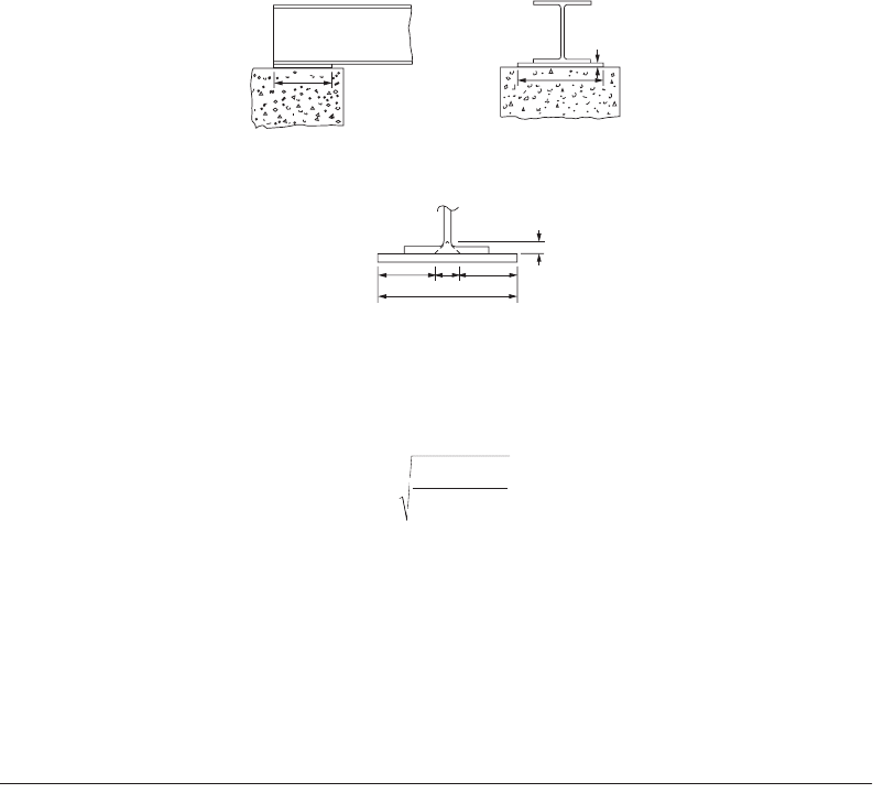
Beam Bearing Plates
Beam bearing plates are provided between main girders and concrete pedestals to distribute the girder
reactions to the concrete supports (Fig. 48.36). Beam bearing plates may also be provided between cross
beams and girders if the cross beams are designed to sit on the girders.
Beam bearing plates are designed based on the limit states of web yielding, web crippling, bearing on
concrete, and plastic bending of the plate. The dimension of the plate along the beam axis, i.e., N, is
determined from the web yielding or web crippling criterion (see Section 48.5 under Criteria for Con-
centrated Loads), whichever is more critical. The dimension B of the plate is determined from Eq. (48.121)
with A
1
calculated using Eq. (48.119). P
u
in Eq. (48.119) is to be replaced by R
u
, the factored reaction at
the girder support.
Bolt Type
(Material)
Minimum
Embedded Length
Minimum
Edge Distance
A307 (A36) 12d 5d > 4 in.
A325 (A449) 17d 7d > 4 in.
Note: d = nominal diameter of the anchor.
A
T
F
g
u
tu
≥
f 075.
L
A
T f
p
ut c
≥ =
¢
()
p
f
p
4
© 2003 by CRC Press LLC
48-86 The Civil Engineering Handbook, Second Edition
Once the size B ¥ N is determined, the plate thickness, t
p
, can be calculated using the equation
(48.131)
where R
u
= the factored girder reaction
F
y
= the yield stress of the plate
n =(B – 2k)/2, in which k is the distance from the web toe of the fillet to the outer surface of
the flange
The above equation was developed based on the assumption that the critical sections for plastic bending
in the plate occur at a distance k from the centerline of the web.
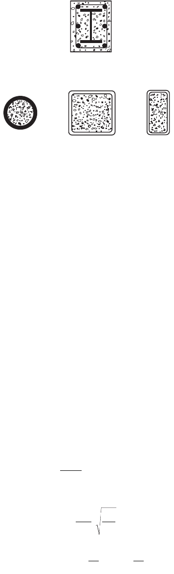
48.13 Composite Members (LRFD Approach)
Composite members are structural members made from two or more materials. The majority of composite
sections used for building constructions are made from steel and concrete, although in recent years the
use of fiber-reinforced polymer (FRP) has been on the rise, especially in the area of structural rehabili-
tation. Composite sections made from steel and concrete utilize the strength provided by steel and the
rigidity provided by concrete. The combination of the two materials often results in efficient load-carrying
members. Composite members may be concrete encased or concrete filled. For concrete-encased mem-
bers (Fig. 48.37a), concrete is cast around steel shapes. In addition to enhancing strength and providing
rigidity to the steel shapes, the concrete acts as a fireproofing material to the steel shapes. It also serves
as a corrosion barrier, shielding the steel from corroding under adverse environmental conditions. For
concrete-filled members (Fig. 48.37b), structural steel tubes are filled with concrete. In both concrete-
encased and concrete-filled sections, the rigidity of the concrete often eliminates the problem of local
buckling experienced by some slender elements of the steel sections.
Some disadvantages associated with composite sections are that concrete creeps and shrinks. Further-
more, uncertainties with regard to the mechanical bond developed between the steel shape and the
concrete often complicate the design of beam-column joints.
Composite Columns
According to the LRFD specification [AISC, 1999], a compression member is regarded as a composite
column if:
FIGURE 48.36 Beam bearing plate.
nn
B
2k
k
B
N
t
p
t
R n
F B N
p
u
y
=
2
090
2
.
© 2003 by CRC Press LLC
Design of Steel Structures 48-87
1. the cross-sectional area of the steel section is at least 4% of the total composite area. If this condition
is not satisfied, the member should be designed as a reinforced concrete column.
2. longitudinal reinforcements and lateral ties are provided for concrete-encased members. The cross-
sectional area of the reinforcing bars shall be 0.007 in.
2
/in. (180 mm
2
/m) of bar spacing. To avoid
spalling, lateral ties shall be placed at a spacing not greater than two thirds the least dimension of
the composite cross section. For fire and corrosion resistance, a minimum clear cover of 1.5 in.
(38 mm) shall be provided.
3. the compressive strength of concrete f
c
¢ used for the composite section falls within the range of
3 ksi (21 MPa) to 8 ksi (55 MPa) for normal weight concrete and not less than 4 ksi (28 MPa) for
lightweight concrete. These limits are set because they represent the range of test data available
for the development of the design equations.
4. the specified minimum yield stress for the steel sections and reinforcing bars used in calculating
the strength of the composite columns does not exceed 60 ksi (415 MPa). This limit is set because
this stress corresponds to a strain below which the concrete remains unspalled and stable.
5. the minimum wall thickness of the steel sections for concrete-filled members is equal to b÷(F
y
/3E)
for rectangular sections of width b and D÷(F
y
/8E) for circular sections of outside diameter D.
Design Compressive Strength
The design compressive strength, f
c
P
n
, shall exceed the factored compressive force, P
u
. The design
compressive strength for f
c
£ 1.5 is given as
(48.132)
where
(48.133)
(48.134)
FIGURE 48.37 Composite columns.
(A) Concrete Encased Composite Section
(B) Concrete Filled Composite Sections
f
l
l
l
l
cn
smy
c
c
2
smy
c
P
A F ,
A F ,
c
=
()
È
Î
Í
˘
˚
˙
£
Ê
Ë
Á
ˆ
¯
˜
È
Î
Í
˘
˚
˙
>
Ï
Ì
Ô
Ô
Ó
Ô
Ô
085 0658 15
085
0 877
15
2
.. .
.
.
.
if
if
l
p
c
m
my
m
KL
r
F
E
=
FFc F
A
A
c f
A
A
my y yr
r
s
c
c
s
=+
Ê
Ë
Á
ˆ
¯
˜
+
¢
Ê
Ë
Á
ˆ
¯
˜
12
© 2003 by CRC Press LLC

48-88 The Civil Engineering Handbook, Second Edition
(48.135)
r
m
= the radius of gyration of steel section and shall not be less than 0.3 times the overall
thickness of the composite cross section in the plane of buckling
A
c
= the area of concrete
A
r
= the area of longitudinal reinforcing bars
A
s
= the area of the steel shape
E = the modulus of elasticity of steel
E
c
= the modulus of elasticity of concrete
F
y
= the specified minimum yield stress of the steel shape
F
yr
= the specified minimum yield stress of longitudinal reinforcing bars
f
c
¢ = the specified compressive strength of concrete
c
1
, c
2
, and c
3
= the coefficients given in the table below.
In addition to satisfying the condition f
c
P
n
≥ P
u
, shear connectors spaced no more than 16 in. (405 mm)
apart on at least two faces of the steel section in a symmetric pattern about the axes of the steel section
shall be provided for concrete-encased composite columns to transfer the interface shear force V
u
¢ between
steel and concrete. V
u
¢ is given by
(48.136)
where V
u
= the axial force in the column
A
s
= the area of steel section
F
y
= the yield strength of the steel section
P
n
= the nominal compressive strength of the composite column without consideration of
slenderness effect
If the supporting concrete area in direct bearing is larger than the loaded area, the bearing condition
for concrete must also be satisfied. Denoting f
c
P
nc
(=f
c
P
n,composite section
– f
c
P
n,steel shape alone
) as the portion of
compressive strength resisted by the concrete and A
B
as the loaded area, the condition that needs to be
satisfied is
(48.137)
Composite Beams
Composite beams used in construction can often be found in two forms: steel beams connected to a
concrete slab by shear connectors, and concrete-encased steel beams.
Steel Beams with Shear Connectors
The design flexure strength for steel beams with shear connectors is f
b
M
n
. The resistance factor f
b
and
nominal moment M
n
are determined as follows:
Type of Composite Section c
1
c
2
c
3
Concrete-encased shapes 0.7 0.6 0.2
Concrete-filled pipes and tubings 1.0 0.85 0.4
EEcE
A
A
mc
c
s
=+
Ê
Ë
Á
ˆ
¯
˜
3
¢
=
-
Ê
Ë
Á
ˆ
¯
˜
Ê
Ë
Á
ˆ
¯
˜
Ï
Ì
Ô
Ô
Ô
Ó
Ô
Ô
Ô
V
V
AF
P
V
AF
P
u
u
sy
n
u
sy
n
1 when the force is applied to the steel section
when the force is applied to the concrete encasement
f
cnc c B
P f A£
¢
[]
06517..
© 2003 by CRC Press LLC

Design of Steel Structures 48-89
Concrete-Encased Steel Beams
For steel beams fully encased in concrete, no additional anchorage for shear transfer is required if (1) at
least 1½ in. (38 mm) of concrete cover is provided on top of the beam and at least 2 in. (51 mm) of
cover is provided over the sides and at the bottom of the beam, and (2) spalling of concrete is prevented
by adequate mesh or other reinforcing steel. The design flexural strength f
b
M
n
can be computed using
either an elastic or plastic analysis.
If an elastic analysis is used, f
b
shall be taken as 0.90. A linear strain distribution is assumed for the
cross section, with zero strain at the neutral axis and maximum strains at the extreme fibers. The stresses
are then computed by multiplying the strains by E (for steel) or E
c
(for concrete). Maximum stress in
steel shall be limited to F
y
, and maximum stress in concrete shall be limited to 0.85f
c
¢. Tensile strength
of concrete shall be neglected. M
n
is to be calculated by integrating the resulting stress block about the
neutral axis.
If a plastic analysis is used, f
b
shall be taken as 0.90 and M
n
shall be assumed to be equal to M
p
, the
plastic moment capacity of the steel section alone.
Composite Beam-Columns
Composite beam-columns shall be designed to satisfy the interaction of Eq. (48.73) or (48.74), whichever
is applicable, with f
c
P
n
calculated based on Eqs. (48.132) to (48.135), P
e
calculated using P
e
= A
s
F
my
/l
c
2
,
and f
b
M
n
calculated using the following equation [Galambos and Chapuis, 1980]:
(48.138)
where Z = the plastic section modulus of the steel section
c
r
= the average of the distance measured from the compression face to the longitudinal
reinforcement in that face, and the distance measured from the tension face to the longi-
tudinal reinforcement in that face
h
1
= the width of the composite section perpendicular to the plane of bending
h
2
= the width of the composite section parallel to the plane of bending
A
r
= the cross-sectional area of longitudinal reinforcing bars
A
w
= the web area of the encased steel shape (=0 for concrete-filled tubes)
F
y
= the yield stress of the steel section
F
yr
= the yield stress of reinforcing bars
If 0 < (P
u
/f
c
P
n
) £ 0.3, a linear interpolation of f
b
M
n
, calculated using the above equation and assuming
that P
u
/f
c
P
n
= 0.3, and that calculated for beams with P
u
/f
c
P
n
= 0 (see above) should be used.
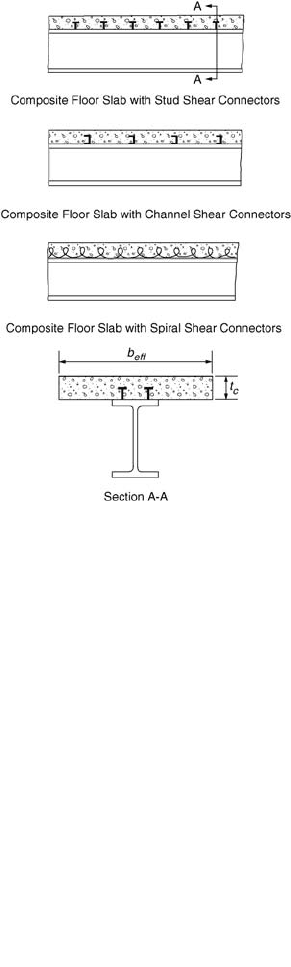
Composite Floor Slabs
Composite floor slabs (Fig. 48.38) can be designed as shored or unshored. In shored construction,
temporary shores are used during construction to support the dead and accidental live loads until the
concrete cures. The supporting beams are designed on the basis of their ability to develop composite
action to support all factored loads after the concrete cures. In unshored construction, temporary shores
Condition f
b
M
n
Positive moment region
and h/t
w
£ 3.76÷(E/F
yf
)
0.85 Determined from plastic stress distribution on the composite section
Positive moment region
and h/t
w
> 3.76÷(E/F
yf
)
0.90 Determined from elastic stress superposition considering the effects of shoring
Negative moment region 0.90 Determined for the steel section alone using equations presented in Section 49.5
f
bn y r ryr
wy
c
wy
M Z F h c A F
h
A F
f h
AF=+-
()
+-
¢
Ê
Ë
Á
ˆ
¯
˜
È
Î
Í
Í
˘
˚
˙
˙
090
1
3
2
217
2
2
1
.
.
© 2003 by CRC Press LLC
48-90 The Civil Engineering Handbook, Second Edition
are not used. As a result, the steel beams alone must be designed to support the dead and accidental live
loads before the concrete has attained 75% of its specified strength. After the concrete is cured, the
composite section should have adequate strength to support all factored loads.
Composite action for the composite floor slabs shown in Fig. 48.38 is developed as a result of the
presence of shear connectors. If sufficient shear connectors are provided so that the maximum flexural
strength of the composite section can be developed, the section is referred to as fully composite. Other-
wise, the section is referred to as partially composite. The flexural strength of a partially composite section
is governed by the shear strength of the shear connectors. The horizontal shear force V
h
, which should
be designed for at the interface of the steel beam and the concrete slab, is given by:
In regions of positive moment:
(48.139)
In regions of negative moment:
(48.140)
where f
c
¢ = the compressive strength of concrete
A
c
= the effective area of the concrete slab, t
c
b
eff
t
c
= the thickness of the concrete slab
b
eff
= the effective width of the concrete slab = smaller of (L/4, s) for an interior beam, and
smaller of (L/8 + distance from beam centerline to edge of slab, s/2 + distance from beam
centerline to edge of slab) for an exterior beam
L = the beam span measured from center-to-center of the supports
s = the spacing between centerlines of adjacent beams
A
s
= the cross-sectional area of the steel beam
FIGURE 48.38 Composite floor slabs.
VfAAF Q
hccsyn
=
¢
Â
()
min . , ,085
VAF Q
hryrn
=Â
()
min ,
© 2003 by CRC Press LLC
Design of Steel Structures 48-91
F
y
= the yield stress of the steel beam
A
r
= the area of reinforcing steel within the effective area of the concrete slab
F
yr
= the yield stress of the reinforcing steel
SQ
n
= the sum of the nominal shear strengths of the shear connectors
The nominal shear strength of a shear connector (used without a formed steel deck) is given by:
For a stud shear connector,
(48.141)
For a channel shear connector,
(48.142)
where A
SC
= the cross-sectional area of the shear stud (in.
2
)
f
c
¢ = the compressive strength of concrete (ksi)
E
c
= the modulus of elasticity of concrete (ksi)
F
u
= the minimum specified tensile strength of the stud shear connector (ksi)
t
f
= the flange thickness of the channel shear connector (in.)
t
w
= the web thickness of the channel shear connector (in.)
L
c
= the length of the channel shear connector (in.)
If a formed steel deck is used, Q
n
must be reduced by a reduction factor. The reduction factor depends
on whether the deck ribs are perpendicular or parallel to the steel beam.
For deck ribs perpendicular to the steel beam,
(48.143)
When only a single stud is present in a rib perpendicular to the steel beam, the reduction factor of
Eq. (48.143) shall not exceed 0.75.
For deck ribs parallel to steel beam
(48.144)
The reduction factor of Eq. (48.144) is applicable only if (w
r
/h
r
) < 1.5, where N
r
is the number of stud
connectors in one rib at a beam intersection, not to exceed three in computations, regardless of the actual
number of studs installed; w
r
is the average width of the concrete rib or haunch; h
r
is the nominal rib
height; and H
s
is the length of stud connector after welding, not to exceed the value h
r
+ 3 in. (75 mm)
in computations, regardless of actual length.
For full composite action, the number of connectors required between the maximum moment point
and the zero moment point of the beam is given by
(48.145)
For partial composite action, the number of connectors required is governed by the condition f
b
M
n
≥
M
u
, where f
b
M
n
is governed by the shear strength of the connectors.
n
sc c c sc u
Q
A fE AF=
¢
£05.
n
fwccc
Q
tt L fE=+
()
¢
03 05..
085
10 10
.
..
N
w
h
H
h
r
r
r
s
r
Ê
Ë
Á
ˆ
¯
˜
Ê
Ë
Á
ˆ
¯
˜
-
È
Î
Í
Í
˘
˚
˙
˙
£
06 10 10...
w
h
H
h
r
r
s
r
È
Î
Í
˘
˚
˙
Ê
Ë
Á
ˆ
¯
˜
-
È
Î
Í
Í
˘
˚
˙
˙
£
N
V
Q
h
n
=
© 2003 by CRC Press LLC
48-92 The Civil Engineering Handbook, Second Edition
The placement and spacing of the shear connectors should comply with the following guidelines:
1. The shear connectors shall be uniformly spaced between the points of maximum moment and
zero moment. However, the number of shear connectors placed between a concentrated load point
and the nearest zero moment point must be sufficient to resist the factored moment M
u
.
2. Except for connectors installed in the ribs of formed steel decks, shear connectors shall have at
least 1 in. (25.4 mm) of lateral concrete cover. The slab thickness above a formed steel deck shall
not be less than 2 in. (51 mm).
3. Unless located over the web, the diameter of shear studs must not exceed 2.5 times the thickness
of the beam flange. For a formed steel deck, the diameter of stud shear connectors shall not exceed
3/4 in. (19 mm) and shall extend not less than 1½ in. (38 mm) above the top of the steel deck.
4. The longitudinal spacing of the studs should fall in the range of six times the stud diameter to
eight times the slab thickness if a solid slab is used, or four times the stud diameter to eight times
the slab thickness or 36 in. (915 mm), whichever is smaller, if a formed steel deck is used. Also,
to resist uplift, the steel deck shall be anchored to all supporting members at a spacing not to
exceed 18 in. (460 mm).
The design flexural strength f
b
M
n
of the composite beam with shear connectors is determined as follows.
In regions of positive moments, for h
c
/t
w
£ 3.76/÷(E/F
yf
), f
b
= 0.85, M
n
is the moment capacity deter-
mined using a plastic stress distribution assuming concrete crushes at a stress of 0.85f
c
¢, and steel yields
at a stress of F
y
. If a portion of the concrete slab is in tension, the strength contribution of that portion of
concrete is ignored. The determination of M
n
using this method is very similar to the technique used for
computing moment capacity of a reinforced concrete beam according to the ultimate strength method.
In regions of positive moments, for h
c
/t
w
> 3.76/÷(E/F
yf
), f
b
= 0.90 and M
n
is the moment capacity
determined using the superposition of elastic stress, considering the effect of shoring. The determination
of M
n
using this method is quite similar to the technique used for computing the moment capacity of a
reinforced concrete beam according to the working stress method.
In regions of negative moment, f
b
M
n
is to be determined for the steel section alone in accordance with
the requirements discussed in Section 48.5. To facilitate design, numerical values of f
b
M
n
for composite
beams with shear studs in solid slabs are given in tabulated form in the AISC-LRFD manual. Values of f
b
M
n
for composite beams with formed steel decks are given in a publication by the Steel Deck Institute [2001].
48.14 Plastic Design
Plastic analysis and design is permitted only for steels with a yield stress not exceeding 65 ksi. The reason
for this is that steels with a high yield stress lack the ductility required for inelastic deformation at hinge
locations. Without adequate inelastic deformation, moment redistribution, which is an important char-
acteristic for plastic design, cannot take place.
In plastic design, the predominant limit state is the formation of plastic hinges. Failure occurs when
enough plastic hinges have formed for a collapse mechanism to develop. To ensure that plastic hinges
can form and can undergo large inelastic rotation, the following conditions must be satisfied:
1. Sections must be compact, that is, the width–thickness ratios of flanges in compression and webs
must not exceed l
p
in Table 48.8.
2. For columns, the slenderness parameter l
c
(see Section 48.4) shall not exceed 1.5K, where K is
the effective length factor, and P
u
from gravity and horizontal loads shall not exceed 0.75A
g
F
y
.
3. For beams, the lateral unbraced length L
b
shall not exceed L
pd
, where for doubly and singly
symmetric I-shaped members loaded in the plane of the web,
(48.146)
L
MM
F
r
pd
p
y
y
=
+
()
3600 2200
1
© 2003 by CRC Press LLC
Design of Steel Structures 48-93
and for solid rectangular bars and symmetric box beams
(48.147)
In the above equations, M
1
is the smaller end moment within the unbraced length of the beam, M
p
is
the plastic moment (=Z
x
F
y
) of the cross-section, r
y
is the radius of gyration about the minor axis (in.),
and F
y
is the specified minimum yield stress (ksi).
L
pd
is not defined for beams bent about their minor axes or for beams with circular and square cross
sections, because these beams do not experience lateral torsional bucking when loaded.
Plastic Design of Columns and Beams
Provided that the above limitations are satisfied, the design of columns shall meet the condition 1.7F
a
A ≥
P
u
, where F
a
is the allowable compressive stress given in Eq. (48.16), A is the gross cross-sectional area,
and P
u
is the factored axial load.
The design of beams shall satisfy the conditions M
p
≥ M
u
and 0.55F
y
t
w
d ≥ V
u
, where M
u
and V
u
are the
factored moment and shear, respectively. M
p
is the plastic moment capacity, F
y
is the minimum specified
yield stress, t
w
is the beam web thickness, and d is the beam depth. For beams subjected to concentrated
loads, all failure modes associated with concentrated loads (see Section 48.5 under Criteria for Concen-
trated Loads) should also be prevented.
Except at the location where the last hinge forms, a beam bending about its major axis must be braced
to resist lateral and torsional displacements at plastic hinge locations. The distance between adjacent
braced points should not exceed l
cr
, given by
(48.148)
where r
y
= the radius of gyration about the weak axis
M = the smaller of the two end moments of the unbraced segment
M
p
= the plastic moment capacity
M/M
p
is taken as positive if the unbraced segment bends in reverse curvature and as negative if the
unbraced segment bends in single curvature.
Plastic Design of Beam-Columns
Beam-columns designed on the basis of plastic analysis shall satisfy the following interaction equations
for stability (Eq. (48.149)) and strength (Eq. (48.150)):
(48.149)
(48.150)
L
MM
F
r
r
F
pd
p
y
y
y
y
=
+
()
≥
5000 3000
3000
1
l
F
r , if
M
M
F
r , if
M
M
cr
y
y
p
y
y
p
=
+
Ê
Ë
Á
ˆ
¯
˜
-< <
Ê
Ë
Á
ˆ
¯
˜
-< £-
Ï
Ì
Ô
Ô
Ô
Ó
Ô
Ô
Ô
1375
25 0 5 10
1375
10 05
..
..
P
P
C M
P
P
M
u
cr
mu
u
e
m
+
-
Ê
Ë
Á
ˆ
¯
˜
£
1
10.
P
P
M
M
u
y
u
p
+£
118
10
.
.
© 2003 by CRC Press LLC