Wai-Fah Chen.The Civil Engineering Handbook
Подождите немного. Документ загружается.

48-74 The Civil Engineering Handbook, Second Edition
For plug welds, the hole diameter shall not be less than the thickness of the part that contains the weld
plus 5/16 in. (8 mm), rounded to the next larger odd 1/16 in. (or even mm), or greater than the minimum
diameter plus 1/8 in. (3 mm) or 2.25 times the thickness of the weld. The center-to-center spacing of
plug welds shall not be less than four times the hole diameter. The thickness of a plug weld in material
less than 5/8 in. (16 mm) thick shall be equal to the thickness of the material. In material over 5/8 in.
(16 mm) thick, the thickness of the weld shall be at least one half the thickness of the material, but not
less than 5/8 in. (16 mm).
For slot welds, the slot length shall not exceed ten times the thickness of the weld. The slot width shall
not be less than the thickness of the part that contains the weld plus 5/16 in. (8 mm), rounded to the
nearest larger odd 1/16 in. (or even mm), or larger than 2.25 times the thickness of the weld. The spacing
of lines of slot welds in a direction transverse to their length shall not be less than four times the width
of the slot. The center-to-center spacing of two slot welds on any line in the longitudinal direction shall
not be less than two times the length of the slot. The thickness of a slot weld in material less than 5/8 in.
(16 mm) thick shall be equal to the thickness of the material. In material over 5/8 in. (16 mm) thick,
the thickness of the weld shall be at least one half the thickness of the material, but not less than 5/8 in.
(16 mm).
For fillet welds, the minimum leg size is given in Table 48.20.
The maximum leg size is equal to the thickness of the connected
part along the edge of a connected part less than 1/4 in. (6 mm)
thick. For thicker parts, the maximum leg size is t minus 1/16 in.
(2 mm), where t is the thickness of the part. The minimum effective
length of a fillet weld is four times its nominal size. If a shorter
length is used, the leg size of the weld shall be taken as 1/4 in. (6
mm) its effective length for the purpose of stress computation. The
effective length of end-loaded fillet welds with lengths up to
100 times the leg dimension can be set equal to the actual length.
If the length exceeds 100 times the weld size, the effective length
shall be taken as the actual length multiplied by a reduction factor, given by [1.2 – 0.002(L/w)] £ 1.0,
where L is the actual length of the end-loaded fillet weld and w is the leg size. The length of longitudinal
fillet welds used alone for flat-bar tension members shall not be less than the perpendicular distance
between the welds. The effective length of any segment of an intermittent fillet weld shall not be less
than four times the weld size or 1½ in. (38 mm).
Welded Connections for Tension Members
Figure 48.22 shows a tension angle member connected to a gusset plate by fillet welds. The applied tensile
force P is assumed to act along the center of gravity of the angle. To avoid eccentricity, the lengths of the
two fillet welds must be proportioned so that their resultant will act along the center of gravity of the
angle. For example, if LRFD is used, the following equilibrium equations can be written:
FIGURE 48.22 An eccentrically loaded welded tension connection.
TA BLE 48.20 Minimum Leg Size
of Fillet Welds (in.)
Thickness of Thicker
Part Joined, t
Minimum
Leg Size
t £ 1/4
1/4 < t £ 1/2
1/2 < t £ 3/4
t > 3/4
1/8
3/16
1/4
5/16
Note: 1 in. = 25.4 mm
L
1
d
1
d
2
P
u
L
2
© 2003 by CRC Press LLC
Design of Steel Structures 48-75
Summing force along the axis of the angle:
(48.112)
Summing moment about the center of gravity of the angle:
(48.113)
where P
u
= the factored axial force
fF
M
= the design strength of the welds as given in Table 48.18
t
eff
= the effective throat thickness
L
1
and L
2
= the lengths of the welds
d
1
and d
2
= the transverse distances from the center of gravity of the angle to the welds.
The two equations can be used to solve for L
1
and L
2
.
Welded Bracket-Type Connections
A typical welded bracket connection is shown in Fig.
48.23. Because the load is eccentric with respect to the
center of gravity of the weld group, the connection is
subjected to both moment and shear. The welds must be
designed to resist the combined effect of direct shear for
the applied load and any additional shear from the
induced moment. The design of the welded bracket con-
nection is facilitated by the use of the design tables in the
AISC-ASD and AISC-LRFD manuals. In both ASD and
LRFD, the load capacity for the connection is given by
(48.114)
where P = the allowable load (in ASD) or factored
load, P
u
(in LRFD) (kips)
l = the length of the vertical weld (in.)
D = the number of sixteenths of an inch in the fillet weld size
C = the coefficient tabulated in the AISC-ASD and AISC-LRFD manuals. In the tables, values
of C for a variety of weld geometries and dimensions are given
C
1
= the coefficient for electrode used (see the following table).
Welded Connections with Welds Subjected to Combined Shear and Flexure
Figure 48.24 shows a welded framed connection and a welded seated connection. The welds for these
connections are subjected to combined shear and flexure. For the purpose of design, it is common practice
to assume that the shear force per unit length, R
S
, acting on the welds is a constant and is given by
(48.115)
Electrode E60 E70 E80 E90 E100 E110
ASD F
v
(ksi)
C
1
18
0.857
21
1.0
24
1.14
27
1.29
30
1.43
33
1.57
LRFD F
EXX
(ksi)
C
1
60
0.857
70
1.0
80
1.03
90
1.16
100
1.21
110
1.34
ff F t L F t L P
M eff M eff u
()
+
()
=
12
ff F t L d F
t
Ld
M eff M
eff
()
=
()
11 22
FIGURE 48.23 An eccentrically loaded welded
bracket connection.
P
U
aL
L
Centroid of
Weld Geometry
PCCDl=
1
R
P
l
S
=
2
© 2003 by CRC Press LLC
48-76 The Civil Engineering Handbook, Second Edition
where P = the allowable load (in ASD) or factored load, P
u
(in LRFD)
l = the length of the vertical weld.
In addition to shear, the welds are subjected to flexure as a result of load eccentricity. There is no
general agreement on how the flexure stress should be distributed on the welds. One approach is to
assume that the stress distribution is linear, with half the weld subjected to tensile flexure stress and half
subjected to compressive flexure stress. Based on this stress distribution and ignoring the returns, the
flexure tension force per unit length of weld, R
F
, acting at the top of the weld can be written as
(48.116)
where e is the load eccentricity.
The resultant force per unit length acting on the weld, R, is then
(48.117)
For a satisfactory design, the value R/t
eff
, where t
eff
is the effective throat thickness of the weld, should
not exceed the allowable values or design strengths given in Table 48.18.
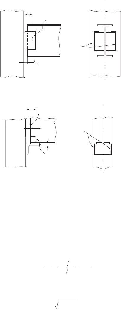
Welded Shear Connections
Figure 48.25 shows three commonly used welded shear connections: a framed beam connection, a seated
beam connection, and a stiffened seated beam connection. These connections can be designed by using
FIGURE 48.24 Welds subjected to combined shear and flexure.
e
Beam Force, P
u
Beam Force, P
u
Welds subjected
to combined
shear and
flexure
nominal setback
1_
2
"
1_
2
"
N_
2
Welded Framed Connection
e
nominal setback
N
t
Welds subjected
to combined
shear and
flexure
Welded Seated Connection
R
Mc
I
Pe l
l
Pe
l
F
==
()
=
2
212
3
32
RRR
SF
=+
22
© 2003 by CRC Press LLC
Design of Steel Structures 48-77
the information presented in the earlier sections on welds subjected to eccentric shear and welds subjected
to combined tension and flexure. For example, the welds that connect the angles to the beam web in the
framed beam connection can be considered eccentrically loaded welds, and Eq. (48.114) can be used for
their design. The welds that connect the angles to the column flange can be considered welds subjected
to combined tension and flexure, and Eq. (48.117) can be used for their design. Like bolted shear
connections, welded shear connections are expected to exhibit appreciable ductility, so the use of angles
with thicknesses in excess of 5/8 in. should be avoided. To prevent shear rupture failure, the shear rupture
strength of the critically loaded connected parts should be checked.
To facilitate the design of these connections, the AISC-ASD and AISC-LRFD manuals provide design
tables by which the weld capacities and shear rupture strengths for different connection dimensions can
be checked readily.
Welded Moment-Resisting Connections
Welded moment-resisting connections (Fig. 48.26), like bolted moment-resisting connections, must be
designed to carry both moment and shear. To simplify the design procedure, it is customary to assume
that the moment, to be represented by a couple F
f
, as shown in Fig. 48.19, is to be carried by the beam
flanges and that the shear is to be carried by the beam web. The connected parts (e.g., the moment plates,
welds, etc.) are then designed to resist the forces F
f
and shear. Depending on the geometry of the welded
connection, this may include checking: (1) the yield or fracture strength of the moment plate, (2) the
shear or tensile capacity of the welds, and (3) the shear rupture strength of the shear plate.
FIGURE 48.25 Welded shear connections: (a) framed beam connection, (b) seated beam connection, (c) stiffened
seated beam connection.
(a) Welded Framed Beam Connection
(b) Welded Seated Beam Connection
(c) Welded Stiffened Seated Beam Connection
Stiffeners
finished to
bear
© 2003 by CRC Press LLC
48-78 The Civil Engineering Handbook, Second Edition
If the column to which the connection is attached is weak, the designer should consider the use of
column stiffeners to prevent failure of the column flange and web due to bending, yielding, crippling,
or buckling (see above, under Design of Moment-Resisting Connections).
Examples of the design of a variety of welded shear and moment-resisting connections can be found
in the AISC manual on connections [AISC, 1992] and in the AISC-LRFD manual [AISC, 2001].
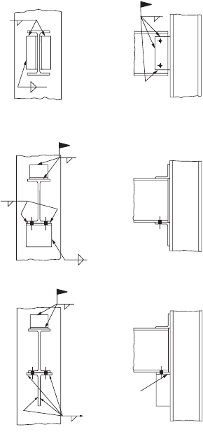
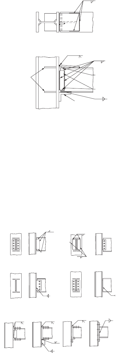
Shop-Welded and Field-Bolted Connections
A large percentage of connections used for construction are shop-welded and field-bolted types. These
connections are usually more cost-effective than fully welded connections, and their strength and ductility
characteristics often rival those of fully welded connections. Figure 48.27 shows some of these connec-
tions. The design of shop-welded and field-bolted connections is also covered in the AISC manual on
connections and in the AISC-LRFD manual. In general, the following should be checked: (1) shear and
FIGURE 48.26 Welded moment connections.
FIGURE 48.27 Shop-welded and field-bolted connections.
+
+
Column Stiffeners
(If Required)
Back-up Bar
Erection Bolts
Bracket or
Seat Angle
+
+
+
(a)
(c)
(a) (b) (c) (d)
(d)
Shop Welded-Field Bolted Shear Connections
Shop Welded-Field Bolted Moment Connections
(b)
© 2003 by CRC Press LLC
Design of Steel Structures 48-79
tensile capacities of the bolts and welds, (2) bearing strength of the connected parts, (3) yield or fracture
strength of the moment plate, and (4) shear rupture strength of the shear plate. Also, as for any other
types of moment connections, column stiffeners shall be provided if any one of the criteria — column
flange bending, local web yielding, crippling, and compression buckling of the column web — is violated.
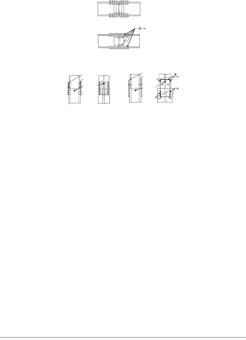
Beam and Column Splices
Beam and column splices (Fig. 48.28) are used to connect beam or column sections of different sizes.
They are also used to connect beams or columns of the same size if the design calls for an extraordinarily
long span. Splices should be designed for both moment and shear, unless the designer intends to utilize
the splices as internal hinges. If splices are used for internal hinges, provisions must be made to ensure
that the connections possess adequate ductility to allow for large hinge rotation.
Splice plates are designed according to their intended functions. Moment splices should be designed
to resist the flange force F
f
= M/(d – t
f
) (Fig. 48.19) at the splice location. In particular, the following
limit states need to be checked: yielding of the gross area of the plate, fracture of the net area of the plate
(for bolted splices), bearing strengths of connected parts (for bolted splices), shear capacity of bolts (for
bolted splices), and weld capacity (for welded splices). Shear splices should be designed to resist the shear
forces acting at the locations of the splices. The limit states that need to be checked include the shear
rupture of the splice plates, the shear capacity of bolts under an eccentric load (for bolted splices), the
bearing capacity of the connected parts (for bolted splices), the shear capacity of bolts (for bolted splices),
and the weld capacity under an eccentric load (for welded splices). Design examples of beam and column
splices can be found in the AISC manual of connections [AISC, 1992] and in the AISC-LRFD manual
[AISC, 2001].
48.12 Column Base Plates and Beam Bearing Plates
(LRFD Approach)
Column Base Plates
Column base plates are steel plates placed at the bottom of columns whose function is to transmit column
loads to the concrete pedestal. The design of a column base plate involves two major steps: (1) determining
the size N ¥ B of the plate, and (2) determining the thickness t
p
of the plate. Generally, the size of the
FIGURE 48.28 Bolted and welded beam and column splices.
Bolted
Welded
Beam Splices
Column Splices
Bolted Welded
Use shims as
required
Use shims as
required
Erection
pin hole
(optional)
Erection
pin hole
(optional)
© 2003 by CRC Press LLC
48-80 The Civil Engineering Handbook, Second Edition
plate is determined based on the limit state of bearing on concrete, and the thickness of the plate is
determined based on the limit state of plastic bending of critical sections in the plate. Depending on the
types of forces (axial force, bending moment, shear force) the plate will be subjected to, the design
procedures differ slightly. In all cases, a layer of grout should be placed between the base plate and its
support for the purpose of leveling, and anchor bolts should be provided to stabilize the column during
erection or to prevent uplift for cases involving a large bending moment.
Axially Loaded Base Plates
Base plates supporting concentrically loaded columns in frames in which the column bases are assumed
pinned are designed with the assumption that the column factored load P
u
is distributed uniformly to
the area of concrete under the base plate. The size of the base plate is determined from the limit state of
bearing on concrete. The design bearing strength of concrete is given by
(48.118)
where f
c
¢ = the compressive strength of concrete
A
1
= the area of the base plate
A
2
= the area of concrete pedestal that is geometrically similar to and concentric with the loaded
area, A
1
£ A
2
£ 4A
1
From Eq. (48.118), it can be seen that the bearing capacity increases when the concrete area is greater
than the plate area. This accounts for the beneficial effect of confinement. The upper limit of the bearing
strength is obtained when A
2
= 4A
1
. Presumably, the concrete area in excess of 4A
1
is not effective in
resisting the load transferred through the base plate.
Setting the column factored load, P
u
, equal to the bearing capacity of the concrete pedestal, f
c
P
p
, and
solving for A
1
from Eq. (48.118), we have
(48.119)
The length, N, and width, B, of the plate should be established so that N ¥ B > A
1
. For an efficient
design, the length can be determined from the equation
(48.120)
where 0.95d and 0.80b
f
define the so-called effective load-bearing area shown crosshatched in Fig. 48.29a.
Once N is obtained, B can be solved from the equation
(48.121)
Both N and B should be rounded up to the nearest full inches.
The required plate thickness, t
req’d
, is to be determined from the limit state of yield line formation
along the most severely stressed sections. A yield line develops when the cross section moment capacity
is equal to its plastic moment capacity. Depending on the size of the column relative to the plate and the
magnitude of the factored axial load, yield lines can form in various patterns on the plate. Figure 48.29
shows three models of plate failure in axially loaded plates. If the plate is large compared to the column,
yield lines are assumed to form around the perimeter of the effective load-bearing area (the crosshatched
area), as shown in Fig. 48.29a. If the plate is small and the column factored load is light, yield lines are
cp c
P f A
A
A
f
=
¢
È
Î
Í
Í
˘
˚
˙
˙
060 085
1
2
1
..
A
A
P
f
u
c
1
2
2
1
06085
=
¢
()
È
Î
Í
Í
˘
˚
˙
˙
..
NA d b
f
ª+ -
()
1
050095 080.. .
B
A
N
=
1
© 2003 by CRC Press LLC
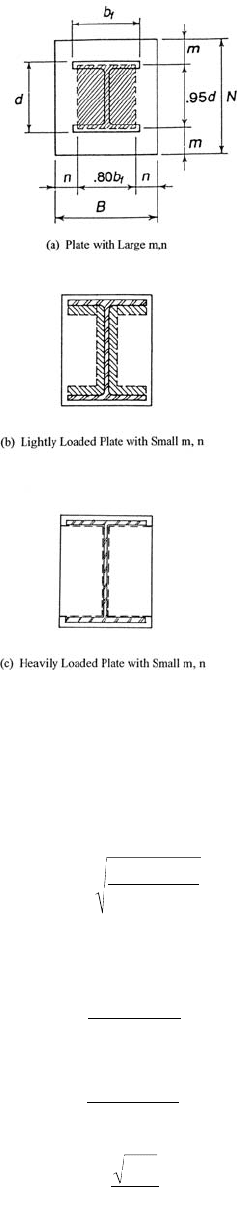
Design of Steel Structures 48-81
assumed to form around the inner perimeter of the I-shaped area, as shown in Fig. 48.29b. If the plate
is small and the column factored load is heavy, yield lines are assumed to form around the inner edge
of the column flanges and both sides of the column web, as shown in Fig. 48.29c. The following equation
can be used to calculate the required plate thickness
(48.122a)
where l is the larger of m, n, and ln¢ given by
(48.122b)
(48.122c)
(48.122d)
FIGURE 48.29 Failure models for centrally loaded column base plates.
tl
P
F B N
r eqd
u
y
¢
=
2
090.
m
N d
=
-
()
095
2
.
n
Bb
f
=
-
()
080
2
.
¢
=n
d b
f
4
© 2003 by CRC Press LLC
48-82 The Civil Engineering Handbook, Second Edition
and
(48.122e)
in which
(48.122f)
Base Plates for Tubular and Pipe Columns
The design concept for base plates discussed above for I-shaped sections can be applied to the design of
base plates for rectangular tubes and circular pipes. The critical section used to determine the plate
thickness should be based on 0.95 times the outside column dimension for rectangular tubes and
0.80 times the outside dimension for circular pipes [Dewolf and Ricker, 1990].
Base Plates with Moments
For columns in frames designed to carry moments at the base, base plates must be designed to support
both axial forces and bending moments. If the moment is small compared to the axial force, the base
plate can be designed without consideration of the tensile force that may develop in the anchor bolts.
However, if the moment is large, this effect should be considered. To quantify the relative magnitude of
this moment, an eccentricity e = M
u
/P
u
is used. The general procedures for the design of base plates for
different values of e are given below [Dewolf and Ricker, 1990].
Small Eccentricity
If e is small (e £ N/6), the bearing stress is assumed to distribute linearly
over the entire area of the base plate (Fig. 48.30). The maximum bearing
stress is given by
(48.123)
where c = N/2 and I = BN
3
/12.
The size of the plate is to be determined by a trial-and-error process.
The size of the base plate should be such that the bearing stress calculated
using Eq. (48.123) does not exceed f
c
P
p
/A
1
, i.e.,
(48.124)
The thickness of the plate is to be determined from
(48.125)
where M
plu
is the moment per unit width of critical section in the plate. M
plu
is to be determined by
assuming that the portion of the plate projecting beyond the critical section acts as an inverted cantilever
loaded by the bearing pressure. The moment calculated at the critical section divided by the length of
the critical section (i.e., B) gives M
plu
.
l=
+-
£
2
11
1
X
X
X
d b
db
P
P
f
f
u
cp
=
+
()
Ê
Ë
Á
Á
ˆ
¯
˜
˜
4
2
f
FIGURE 48.30 Eccentrically
loaded column base plate (small
load eccentricity).
M
u
P
u
f
max
N
f
min
e = ≤
P
u
M
u
6
N
f
P
B N
M c
I
uu
max
=+
060 085 060 17
2
1
.. .. f
A
A
f
cc
¢
È
Î
Í
Í
˘
˚
˙
˙
£
¢
[]
t
M
F
p
plu
y
=
4
090.
© 2003 by CRC Press LLC
Design of Steel Structures 48-83
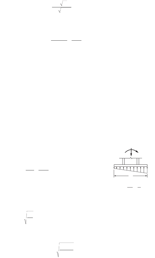
Moderate Eccentricity
For plates subjected to moderate moments (N/6 < e £ N/2), only a portion
of the plate will be subjected to bearing stress (Fig. 48.31). Ignoring the
tensile force in the anchor bolt in the region of the plate where no bearing
occurs and denoting A as the length of the plate in bearing, the maximum
bearing stress can be calculated from force equilibrium consideration as
(48.126)
where A = 3(N/2 – e) is determined from moment equilibrium. The plate
should be proportioned such that f
max
does not exceed the value calculated
using Eq. (48.124). t
p
is to be determined from Eq. (48.125).
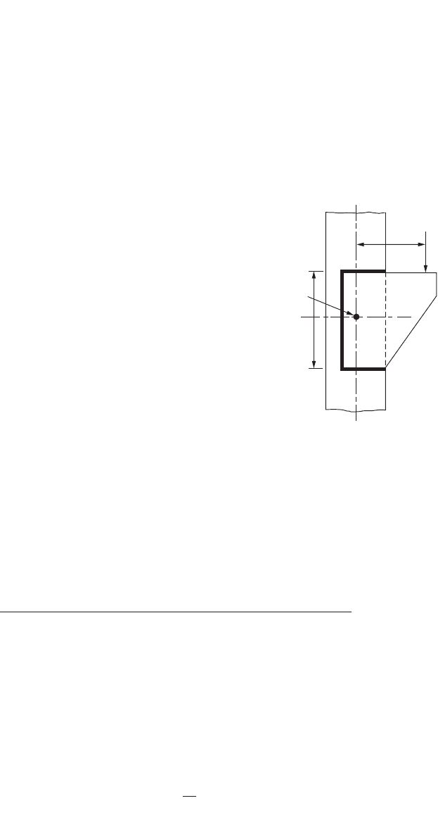
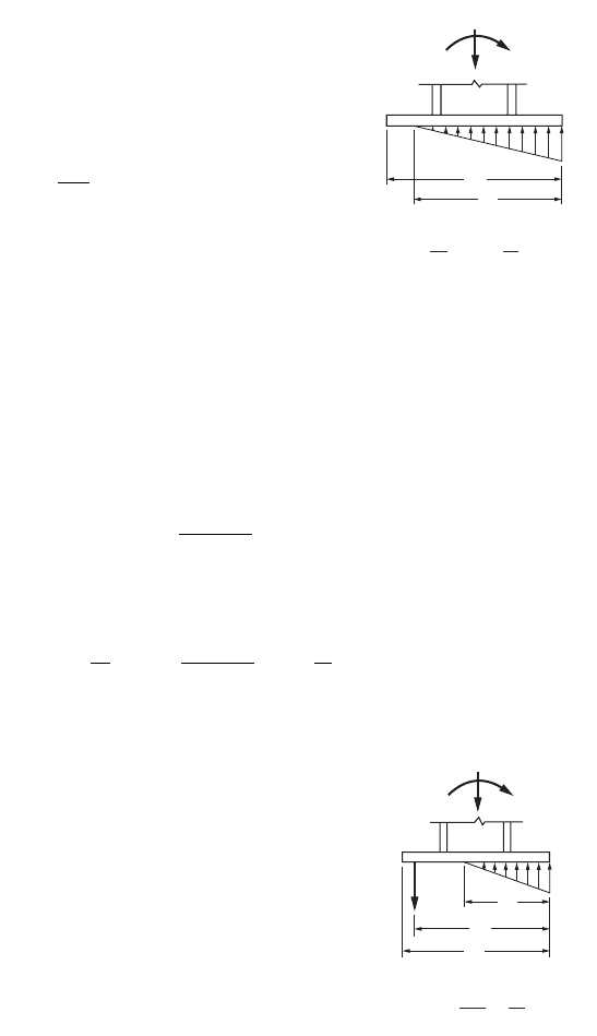
Large Eccentricity
For plates subjected to large bending moments so that e > N/2, one needs
to take into consideration the tensile force that develops in the anchor
bolts (Fig. 48.32). Denoting T as the resultant force in the anchor bolts, A as the depth of the compressive
stress block, and N ¢ as the distance from the line of action of the tensile force to the extreme compression
edge of the plate, force equilibrium requires that
(48.127)
and moment equilibrium requires that
(48.128)
The above equations can be used to solve for A and T. The size of the
plate is determined using a trial-and-error process. The size should be
chosen such that f
max
does not exceed the value calculated using Eq.
(48.124), A should be smaller than N ¢, and T should not exceed the tensile
capacity of the bolts.
Once the size of the plate is determined, the plate thickness t
p
is calcu-
lated using Eq. (48.125). Note that there are two critical sections on the
plate, one on the compression side of the plate and the other on the
tension side of the plate. Two values of M
plu
are to be calculated, and the
larger value should be used to calculate t
p
.
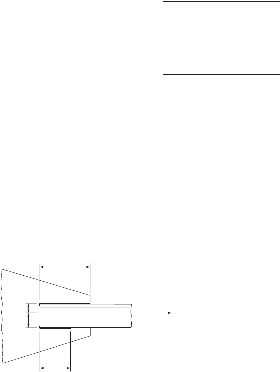
Base Plates with Shear
Under normal circumstances, the factored column base shear is ade-
quately resisted by the frictional force developed between the plate and
its support. Additional shear capacity is also provided by the anchor bolts.
For cases in which an exceptionally high shear force is expected, such as
in a bracing connection, or in which uplift occurs that reduces the fric-
tional resistance, the use of shear lugs may be necessary. Shear lugs can be designed based on the limit
states of bearing on concrete and bending of the lugs. The size of the lug should be proportioned such
that the bearing stress on concrete does not exceed 0.60(0.85f
c
¢). The thickness of the lug can be deter-
mined from Eq. (48.125). M
plu
is the moment per unit width at the critical section of the lug. The critical
section is taken to be at the junction of the lug and the plate (Fig. 48.33).
FIGURE 48.31 Eccentrically
loaded column base plate
(moderate load eccentricity).
M
u
P
u
N
A
f
max
e
< ≤
2
N
6
N
f
P
AB
u
max
=
2
TP
f
AB
u
+=
max
2
P N
N
M
f
AB
N
A
u
¢
-
Ê
Ë
Á
ˆ
¯
˜
+=
¢
-
Ê
Ë
Á
ˆ
¯
˜
223
max
FIGURE 48.32 Eccentrically
loaded column base plate (large
load eccentricity).
M
u
P
u
f
max
A
T
N′
N
e = >
P
u
M
u
2
N
© 2003 by CRC Press LLC