Wai-Fah Chen.The Civil Engineering Handbook
Подождите немного. Документ загружается.

48-54 The Civil Engineering Handbook, Second Edition
Bearing Stiffeners
Bearing stiffeners must be provided for a plate girder at unframed girder ends and at points of concen-
trated loads where the web yielding or the web crippling criterion is violated (see Section 48.5 under
Criteria for Concentrated Loads). Bearing stiffeners shall be provided in pairs and extend from the upper
flange to the lower flange of the girder. Denoting b
st
as the width of one stiffener and t
st
as its thickness,
bearing stiffeners shall be portioned to satisfy the limit states as follows.
For the limit state of local buckling,
(48.97)
For the limit state of compression, the design compressive strength, f
c
P
n
, must exceed the required
compressive force acting on the stiffeners. f
c
P
n
is to be determined based on an effective length factor K
of 0.75 and an effective area, A
eff
, equal to the area of the bearing stiffeners plus a portion of the web.
For end bearing, this effective area is equal to 2(b
st
t
st
) + 12t
w
2
, and for interior bearing, this effective area
is equal to 2(b
st
t
st
) + 25t
w
2
, where t
w
is the web thickness. The slenderness parameter, l
c
, is to be calculated
using a radius of gyration r = ÷(I
stt
/A
eff
), where I
st
= t
st
(2b
st
+ t
w
)
3
/12.
For the limit state of bearing, the bearing strength, fR
n
, must exceed the required compression force
acting on the stiffeners. fR
n
is given by
(48.98)
where F
y
= the yield stress
A
pb
= the bearing area.
Intermediate Stiffeners
Intermediate stiffeners shall be provided if (1) the shear strength capacity is calculated based on tension
field action, (2) the shear criterion is violated (i.e., when the V
u
exceeds f
v
V
n
), or (3) the web slenderness
h/t
w
exceeds 2.45÷(E/F
yw
). Intermediate stiffeners can be provided in pairs or on one side of the web only
in the form of plates or angles. They should be welded to the compression flange and the web, but they
may be stopped short of the tension flange. The following requirements apply to the design of intermediate
stiffeners.
Local Buckling — The width–thickness ratio of the stiffener must be proportioned so that Eq. (48.97) is
satisfied to prevent failure by local buckling.
Stiffener Area — The cross-section area of the stiffener must satisfy the following criterion:
(48.99)
where F
y
is the yield stress of stiffeners and D is 1.0 for stiffeners in pairs, 1.8 for single-angle stiffeners,
and 2.4 for single-plate stiffeners. The other terms in Eq. (48.99) are defined as before, in Eqs. (48.94)
and (48.95).
Stiffener Moment of Inertia — The moment of inertia for stiffener pairs taken about an axis in the web
center or for single stiffeners taken about the face of contact with the web plate must satisfy the following
criterion:
(48.100)
b
t
E
F
st
st y
£ 056.
f R F A
nypb
≥
[]
07518..
A
F
F
Dht C
V
V
t
st
yw
y
wv
u
vn
w
≥ -
()
-
È
Î
Í
˘
˚
˙
≥015 1 18 0
2
.
f
Ia t
ah
at
st w w
≥
()
-
È
Î
Í
Í
˘
˚
˙
˙
≥
3
2
3
25
205
.
.
© 2003 by CRC Press LLC
Design of Steel Structures 48-55
Stiffener Length — The length of the stiffeners, l
st
, should fall within the range
(48.101)
where h = the clear distance between the flanges less the widths of the flange-to-web welds
t
w
= the web thickness
If intermittent welds are used to connect the stiffeners to the girder web, the clear distance between
welds shall not exceed 16t
w
or 10 in. (25.4 cm). If bolts are used, their spacing shall not exceed 12 in.
(30.5 cm).
Stiffener Spacing — The spacing of the stiffeners, a, shall be determined from the shear criterion f
v
V
n
≥
V
u
. This spacing shall not exceed the smaller of 3h and [260/(h/t
w
)]
2
h.
Example 48.7
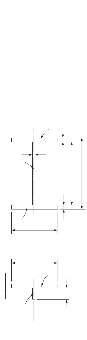
Using LRFD, design the cross section of an I-shaped plate girder, shown in Fig. 48.12a, to support a
factored moment M
u
of 4600 kip-ft (6240 kN-m); the dead weight of the girder is included. The girder
is a 60-ft (18.3-m)-long simply supported girder. It is laterally supported at every 20-ft (6.1-m) interval.
Use A36 steel.
FIGURE 48.12 Design of a plate girder cross section.
h t
l
h t
w
st
w
-<<-66
y
(a) Plate Girder Nomenclature
(b) Calculation of r
T
d
h
A
f
A
f
b
f
t
w
t
f
y
t
w
A
w
xx
/6
A
w
b
f
A
f
t
f
h/6
T
T
© 2003 by CRC Press LLC
48-56 The Civil Engineering Handbook, Second Edition
Proportion of the girder web:
Ordinarily, the overall depth-to-span ratio d/L of a building girder is in the range of 1/12 to 1/10. So, let
us try h = 70 in.
Also, because h/t
w
of a plate girder is normally in the range of 5.70÷(E/F
yf
) to 11.7÷(E/F
yf
), using E =
29,000 ksi and F
yf
= 36 ksi, let’s try t
w
= 5/16 in.
Proportion of the girder flanges:
For a preliminary design, the required area of the flange can be determined using the flange area method:
So, let b
f
= 20 in. and t
f
= 1⅛ in., giving A
f
= 22.5 in.
2
Determine the design flexural strength
f
b
M
n
of the girder:
Calculate I
x
:
Calculate S
xt
and S
xc
:
Calculate r
T
(refer to Fig. 48.12b):
Calculate F
cr
:
For flange local buckling (FLB),
For lateral torsional buckling (LTB),
Calculate R
PG
:
A
M
F h
f
u
y
ª=
¥
()()
=
4600 12
36 70
21 7
kip-ft in ft
ksi in
in
2
.
IIA y
xiii
=+
[]
=+
()()
++
()( )
[]
=
Â
2
22
8932 21 88 0 2 2 37 22 5 35 56
65840
.][. ..
in
4
SS
I
c
I
c
xt xc
x
t
x
c
= ===
+
=
65840
35 1 125
1823
.
in
3
r
I
A A
T
T
fw
=
+
=
()()
+
()
()
+
()
=
1
6
1 125 20 12 11 667 5 16 12
22 5
1
6
21 88
536
3
3
..
..
.in.
b
t
E
F
F F
f
fyf
cr yf
2
20
21125
889 038 10 8=
()
=
È
Î
Í
Í
˘
˚
˙
˙
<=
È
Î
Í
Í
˘
˚
˙
˙
==
.
.. .so, 36 ksi
L
r
<
E
F
F F
b
Tyf
cr yf
=
¥
=
È
Î
Í
˘
˚
˙
=
È
Î
Í
Í
˘
˚
˙
˙
==
20 12
536
44 8 1 76 50
.
.. so, 36 ksi
R
a
ht EF
a
PG
r
cw cr
r
=-
-
()
Ê
Ë
ˆ
¯
+
()
=-
()
-
()
[]
+
()
[]
=1
570
1 200 300
1
0 972 70 5 16 5 70 29 000 36
1200 300 0 972
096
.
,
..,
.
.
© 2003 by CRC Press LLC
Design of Steel Structures 48-57
Calculate f
b
M
n
:
Since [f
b
M
n
= 4725 kip-ft] > [M
u
= 4600 kip-ft], the cross section is acceptable.
Use web plate 5/16 x 70 in. and two flange plates 1⅛ x 20 in. for the girder cross section.
Example 48.8
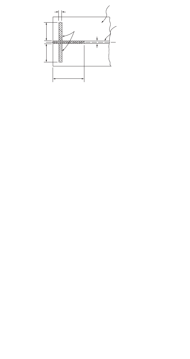
Design bearing stiffeners for the plate girder of the preceding example for a factored end reaction of
260 kips.
Since the girder end is unframed, bearing stiffeners are required at the supports. The size of the
stiffeners must be selected to ensure that the limit states of local buckling, compression, and bearing are
not violated.
Limit state of local buckling:
Refer to Fig. 48.13; try b
st
= 8 in. To avoid problems with local buckling, b
st
/2t
st
must not exceed 0.56÷(E/F
y
) =
15.8. Therefore, try t
st
= 1/2 in. So, b
st
/2t
st
= 8, which is less than 15.8.
Limit state of compression:
A
eff
= 2(b
st
t
st
) + 12t
w
2
= 2(8)(0.5) + 12(5/16)
2
= 9.17 in.
2
I
st
= t
st
(2b
st
+ t
w
)
3
/12 = 0.5[2(8) + 5/16]
3
/12 = 181 in.
4
r
st
= ÷(I
st
/A
eff
) = ÷(181/9.17) = 4.44 in.
Kh/r
st
= 0.75(70)/4.44 = 11.8
l
c
= (Kh/pr
st
)÷(F
y
/E) = (11.8/3.142)÷(36/29,000) = 0.132
and from Eq. (48.17),
Since f
b
P
n
> 260 kips, the design is satisfactory for compression.
FIGURE 48.13 Design of bearing stiffeners.
Plate Girder Web
Plate Girder Flange
Bearing
Stiffeners
t
st
t
w
12t
w
b
st
b
st
bn
xt e yt
xPGecr
M
SRF
SR RF
f
=
=
()( )()()
=
=
()( )()()()
=
Ï
Ì
Ô
Ó
Ô
=
=
smaller of
0.90 0.90 59,065 kip-in.
0.90 . . 56,700 kip-in.
56,700 kip-in.
4725 kip-ft .
1823 1 36
090 1823 0 96 1 36
cn y st
PF A
f
l
=
()
=
()()()
=085 0658 085 0658 36 9 17 279
2
2
0 132
.. .. . kips
.
© 2003 by CRC Press LLC

48-58 The Civil Engineering Handbook, Second Edition
Limit state of bearing:
Assuming there is a 1/4-in. weld cutout at the corners of the bearing stiffeners at the junction of the
stiffeners and the girder flanges, the bearing area for the stiffener pairs is A
pb
= (8 – 0.25)(0.5)(2) =
7.75 in.
2
. Substituting this into Eq. (48.98), we have fR
n
= 0.75(1.8)(36)(7.75) = 377 kips, which exceeds
the factored reaction of 260 kips. So bearing is not a problem.
Use two 1/2 ¥ 8 in. plates for bearing stiffeners.
48.11 Connections
Connections are structural elements used for joining different members of a framework. Connections
can be classified according to:
1. the type of connecting medium used: bolted connections, welded connections, bolted–welded
connections, riveted connections
2. the type of internal forces the connections are expected to transmit: shear (semirigid, simple)
connections, moment (rigid) connections
3. the type of structural elements that made up the connections: single-plate-angle connections,
double-web-angle connections, top- and seated-angle connections, seated beam connections, etc.
4. the type of members the connections are joining: beam-to-beam connections (beam splices),
column-to-column connections (column splices), beam-to-column connections, hanger connec-
tions, etc.
To properly design a connection, a designer must have a thorough understanding of the behavior of
the joint under loads. Different modes of failure can occur depending on the geometry of the connection
and the relative strengths and stiffnesses of the various components of the connection. To ensure that
the connection can carry the applied loads, a designer must check for all perceivable modes of failure
pertinent to each component of the connection and the connection as a whole.
Bolted Connections
Bolted connections are connections whose components are fastened together primarily by bolts. The
four basic types of bolts are discussed in Section 48.1 under Structural Fasteners. Depending on the
direction and line of action of the loads relative to the orientation and location of the bolts, the bolts
may be loaded in tension, shear, or a combination of tension and shear. For bolts subjected to shear
forces, the design shear strength of the bolts also depends on whether or not the threads of the bolts are
excluded from the shear planes. A letter X or N is placed at the end of the ASTM designation of the bolts
to indicate whether the threads are excluded or not excluded, respectively, from the shear planes. Thus,
A325-X denotes A325 bolts whose threads are excluded from the shear planes, and A490-N denotes A490
bolts whose threads are not excluded from the shear planes. Because of the reduced shear areas for bolts
whose threads are not excluded from the shear planes, these bolts have lower design shear strengths than
their counterparts whose threads are excluded from the shear planes.
Bolts can be used in both bearing-type connections and slip-critical connections. Bearing-type con-
nections rely on the bearing between the bolt shanks and the connecting parts to transmit forces. Some
slippage between the connected parts is expected to occur for this type of connection. Slip-critical
connections rely on the frictional force that develops between the connecting parts to transmit forces.
No slippage between connecting elements is expected for this type of connection. Slip-critical connections
are used for structures designed for vibratory or dynamic loads, such as bridges, industrial buildings,
and buildings in regions of high seismicity. Bolts used in slip-critical connections are denoted by the
letter F after their ASTM designation, e.g., A325-F, A490-F.
Holes made in the connected parts for bolts may be standard size, oversize, short slotted, or long
slotted. Table 48.10 gives the maximum hole dimension for ordinary construction usage.
© 2003 by CRC Press LLC

Design of Steel Structures 48-59
Standard holes can be used for both bearing-type and slip-critical connections. Oversize holes shall
be used only for slip-critical connections, and hardened washers shall be installed over these holes in an
outer ply. Short-slotted and long-slotted holes can be used for both bearing-type and slip-critical con-
nections, provided that when such holes are used for bearing, the direction of slot is transverse to the
direction of loading. While oversize and short-slotted holes are allowed in any or all plies of the connec-
tion, long-slotted holes are allowed only in one of the connected parts. In addition, if long-slotted holes
are used in an outer ply, plate washers, or a continuous bar with standard holes having a size sufficient
to cover, the slot shall be provided.
Bolts Loaded in Tension
If a tensile force is applied to the connection such that the direction of load is parallel to the longitudinal
axes of the bolts, the bolts will be subjected to tension. The following conditions must be satisfied for
bolts under tensile stresses.
Allowable Stress Design
For ASD the condition is
(48.102)
where f
t
= the computed tensile stress in the bolt
F
t
= the allowable tensile stress in the bolt (see Table 48.11)
Load and Resistance Factor Design
For LRFD the condition is
(48.103)
where f
t
= 0.75, f
t
is the tensile stress produced by factored loads (ksi)
F
t
= the nominal tensile strength given in Table 48.11
Bolts Loaded in Shear
When the direction of load is perpendicular to the longitudinal axes of the bolts, the bolts will be subjected
to shear. The conditions that need to be satisfied for bolts under shear stresses are as follows.
Allowable Stress Design
For bearing-type and slip-critical connections, the condition is
(48.104)
where f
v
= the computed shear stress in the bolt (ksi)
F
v
= the allowable shear stress in the bolt (see Table 48.12)
TA BLE 48.10 Nominal Hole Dimensions (in.)
Bolt
Diameter, d
(in.)
Hole Dimensions
Standard
(Diameter)
Oversize
(Diameter)
Short Slot
(Width ¥ Length)
Long Slot
(Width ¥ Length)
1/2
5/8
3/4
7/8
1
≥1⅛
9/16
11/16
13/16
15/16
1
⁄
d + 1/16
5/8
13/16
15/16
1
⁄
1¼
d + 5/16
9/16 ¥ 11/16
11/16 ¥ 7/8
13/16 ¥ 1
15/16 ¥ 1⅛
1
⁄
¥ 1
⁄
(d + 1/16) ¥ ( d + 3/8)
9/16 ¥ 1¼
11/16 ¥ 1
⁄
13/16 ¥ 1
⁄
15/16 ¥ 2
⁄
1
⁄
¥ 2½
(d + 1/16) ¥ (2.5d)
Note: 1 in. = 25.4 mm
fF
tt
£
tt
t
F
f
f
≥
fF
vv
£
© 2003 by CRC Press LLC

48-60 The Civil Engineering Handbook, Second Edition
Load and Resistance Factor Design
For bearing-type connections designed at factored loads and for slip-critical connections designed at
service loads, the condition is
TA BLE 48.11 F
t
of Bolts (ksi) (1 ksi = 6.895 MPa)
ASD LRFD
Bolt
Type
F
t
(Static
Loading)
F
t
(Fatigue Loading)
F
t
(Static
Loading)
F
t
(Fatigue Loading)
A307 20 Not allowed 45 Not allowed
A325
A490
44
54
If N £ 20,000:
F
t
= same as for static loading
If 20,000 < N £ 500,000:
F
t
= 40 (A325)
= 49 (A490)
If N > 500,000:
F
t
= 31 (A325)
= 38 (A490)
where
N = number of stress range
fluctuations in the design
life
F
u
= minimum specified
tensile strength (ksi)
90
113
F
t
is not defined, but the condition F
t
< F
SR
needs to be satisfied
where
f
t
= tensile stress caused by service loads
calculated using a net tensile area given by
F
SR
is the design stress range given by
in which
d
b
= nominal bolt diameter
n = threads per inch
N = number of stress range fluctuations in the
design life
TA BLE 48.12 F
v
or F
n
of Bolts (ksi) (1 ksi = 6.895 MPa)
Bolt
Type F
v
for ASD F
v
for LRFD
A307 10.0
a
(regardless of whether or not threads are
excluded from shear planes)
24.0
a
(regardless of whether or not threads are
excluded from shear planes)
A325-N 21.0
a
48.0
a
A325-X 30.0
a
60.0
a
A325-F
b
17.0 for standard size holes
15.0 for oversize and short-slotted holes
12.0 for long-slotted holes when direction of load
is transverse to the slots
10.0 for long-slotted holes when direction of load
is parallel to the slots
17.0 for standard size holes
15.0 for oversize and short-slotted holes
12.0 for long-slotted holes when direction of load is
transverse to the slots
10.0 for long-slotted holes when direction of load is
parallel to the slots
A490-N 28.0
a
60.0
a
A490-X 40.0
a
75.0
a
A490-F
b
21.0 for standard size holes
18.0 for oversize and short-slotted holes
15.0 for long-slotted holes when direction of load
is transverse to the slots
13.0 for long-slotted holes when direction of load
is parallel to the slots
21.0 for standard size holes
18.0 for oversize and short-slotted holes
15.0 for long-slotted holes when direction of load is
transverse to the slots
13.0 for long-slotted holes when direction of load is
parallel to the slots
a
Ta bulated values shall be reduced by 20% if the bolts are used to splice tension members having a fastener pattern
whose length, measured parallel to the line of action of the force, exceeds 50 in. (127 cm).
b
Ta bulated values are applicable only to class A surfaces, i.e., unpainted clean mill surfaces and blast-cleaned surfaces
with class A coatings (with slip coefficient = 0.33). For design strengths with other coatings, see Load and Resistance
Factor Design Specification for Structural Joints Using ASTM A325 or A490 Bolts [RCSC, 2000].
Ad
n
tb
=-
Ê
Ë
Á
ˆ
¯
˜
p
4
0 9743
2
.
F
N
SR
=
¥
Ê
Ë
Á
ˆ
¯
˜
39 10
8
13
.
© 2003 by CRC Press LLC

Design of Steel Structures 48-61
(48.105)
where f
v
= 0.75 for bearing-type connections design for factored loads and 1.00 for slip-critical
connections designed at service loads
f
v
= the shear stress produced by factored loads for bearing-type connections and by service
loads for slip-critical connections (ksi)
F
v
= the nominal shear strength given in Table 48.12
For slip-critical connections designed at factored loads, the condition is
(48.106)
where f = 1.0 for standard holes, 0.85 for oversize and short-slotted holes, 0.70 for long-slotted holes
transverse to the direction of load, and 0.60 for long-slotted holes parallel to the direction
of load
r
str
= the design slip resistance per bolt, 1.13mT
b
N
s
m = 0.33 for class A surfaces (i.e., unpainted clean mill surfaces or blast-cleaned surfaces with
class A coatings), 0.50 for class B surfaces (i.e., unpainted blast-cleaned surfaces or blast-
cleaned surfaces with class B coatings), and 0.35 for class C surfaces (i.e., hot-dip galvanized
and roughened surfaces)
T
b
= the minimum fastener tension given in Table 48.13
N
s
= the number of slip planes
r
u
= the required force per bolt due to factored loads
Bolts Loaded in Combined Tension and Shear
If a tensile force is applied to a connection such that its line of action is at an angle with the longitudinal
axes of the bolts, the bolts will be subjected to combined tension and shear. The conditions that need to
be satisfied are given below.
Allowable Stress Design
The conditions are
(48.107)
where f
v
and F
v
= as defined in Eq. (48.104)
f
t
= the computed tensile stress in the bolt (ksi)
F
t
= the allowable tensile stress given in Table 48.14
Load and Resistance Factor Design
For bearing-type connections designed at factored loads and slip-critical connections designed at service
loads, the conditions are
TA BLE 48.13 Minimum Fastener Tension (kips)
Bolt Diameter (in.) A325 Bolts A490 Bolts
1/2 12 15
5/8 19 24
3/4 28 35
7/8 39 49
15164
1⅛ 56 80
1¼ 71 102
1⅜ 85 121
1½ 103 148
vv
v
F
f
f
≥
frr
str u
≥
fF f F
vv tt
££and
© 2003 by CRC Press LLC

48-62 The Civil Engineering Handbook, Second Edition
(48.108)
where f
v
, F
v
, and f
v
= as defined in Eq. (48.105),
f
t
= 0.75
f
t
= the tensile stress due to factored loads for bearing-type connections and to service
loads for slip-critical connections (ksi)
F
t
= the nominal tension stress limit for combined tension and shear given in Table 48.14
For slip-critical connections designed at factored loads, the condition is given in Eq. (48.106), except
that the design slip resistance per bolt fr
str
shall be multiplied by a reduction factor given by 1 –
T
u
/(1.13T
b
N
b
), where T
u
is the factored tensile load on the connection, T
b
is given in Table 48.13, and
N
b
is the number of bolts carrying the factored load tension T
u
.
Bearing Strength at Fastener Holes
Connections designed on the basis of bearing rely on the bearing force developed between the fasteners
and the holes to transmit forces and moments. The limit state for bearing must therefore be checked to
ensure that bearing failure will not occur. Bearing strength is independent of the type of fastener. This
is because the bearing stress is more critical on the parts being connected than on the fastener itself. The
AISC specification provisions for bearing strength are based on preventing excessive hole deformation.
As a result, bearing capacity is expressed as a function of the type of holes (standard, oversize, slotted),
bearing area (bolt diameter times the thickness of the connected parts), bolt spacing, edge distance (L
e
),
strength of the connected parts (F
u
), and the number of fasteners in the direction of the bearing force.
TABLE 48.14 F
t
for Bolts under Combined Tension and Shear (ksi) (1 ksi = 6.895 MPa)
Bearing-Type Connections
Bolt
Type
ASD LRFD
Threads Not
Excluded from
the Shear Plane
Threads
Excluded from
the Shear Plane
Threads Not
Excluded from
the Shear Plane
Threads
Excluded from
the Shear Plane
A307 26 – 1.8f
v
£ 20 59 – 2.5f
v
£ 45
A325 ÷(44
2
– 4.39f
v
2
) ÷(44
2
– 2.15f
v
2
) 117 – 2.5f
v
£ 90 117 – 2.0f
v
£ 90
A490 ÷(54
2
–
3.75f
v
2
) ÷(54
2
– 1.82f
v
2
) 147 – 2.5f
v
£ 113 147 – 2.0f
v
£ 113
Slip-Critical Connections
For ASD:
Only f
v
£ F
v
needs to be checked
where
f
v
= computed shear stress in the bolt (ksi)
F
v
= [1 – (f
t
A
b
/T
b
)] ¥ (values of F
v
given in Table 48.12)
f
t
= computed tensile stress in the bolt (ksi)
A
b
= nominal cross-sectional area of bolt (in.
2
)
T
b
= minimum pretension load given in Table 48.13
For LRFD:
Only f
v
F
v
≥ f
v
needs to be checked
where
f
v
=1.0
f
v
= shear stress produced by service load
F
v
= [1 – (T/0.8T
b
N
b
)] ¥ (values of F
v
given in Table 48.12)
T = service tensile force in the bolt (kips)
T
b
= minimum pretension load given in Table 48.13
N
b
= number of bolts carrying the service load tension T
vv
v
tt
t
F
f
F
f
ff
≥≥and
© 2003 by CRC Press LLC

Design of Steel Structures 48-63
Table 48.15 summarizes the expressions and conditions used in ASD and LRFD for calculating the bearing
strength of both bearing-type and slip-critical connections.
Minimum Fastener Spacing
To ensure safety and efficiency and to maintain clearances between bolt nuts, as well as to provide room
for wrench sockets, the fastener spacing, s, should not be less than 3d, where d is the nominal fastener
diameter.
Minimum Edge Distance
To prevent excessive deformation and shear rupture at the edge of the connected part, a minimum edge
distance L
e
must be provided in accordance with the values given in Table 48.16 for standard holes. For
oversize and slotted holes, the values shown must be incremented by C
2
, given in Table 48.17.
Maximum Fastener Spacing
A limit is placed on the maximum value for the spacing between adjacent fasteners to prevent the
possibility of gaps forming or buckling from occurring in between fasteners when the load to be trans-
mitted by the connection is compressive. The maximum fastener spacing measured in the direction of
the force is given as follows.
For painted members or unpainted members not subject to corrosion, the maximum fastener spacing
is the smaller of 24t, where t is the thickness of the thinner plate and 12 in. (305 mm).
For unpainted members of weathering steel subject to atmospheric corrosion, the maximum fastener
spacing is the smaller of 14t, where t is the thickness of the thinner plate and 7 in. (178 mm).
TABLE 48.15 Bearing Capacity
Conditions
ASD LRFD
Allowable
Bearing Stress, F
p
(ksi)
Design Bearing
Strength, fR
n
(kips)
1. For standard, oversize, or short-slotted holes loaded in any direction L
e
F
u
/2d £ 1.2F
u
0.75[1.2L
c
tF
u
]
£0.75[2.4dtF
u
]
a
2. For long-slotted holes with direction of slot perpendicular to the
direction of bearing
L
e
F
u
/2d £ 1.0F
u
0.75[1.0L
c
tF
u
]
£0.75[2.0dtF
u
]
3. If hole deformation at service load is not a design consideration L
e
F
u
/2d £ 1.5F
u
0.75[1.5L
c
tF
u
]
£0.75[3.0dtF
u
]
Note: L
e
= distance from free edge to center of the bolt; L
c
= clear distance, in the direction of force, between
the edge of the hole and the edge of the adjacent hole or edge of the material; d = nominal bolt diameter; t =
thickness of the connected part; F
u
= specified minimum tensile strength of the connected part.
a
This equation is also applicable to long-slotted holes when the direction of the slot is parallel to the direction
of the bearing force.
TA BLE 48.16 Minimum Edge Distance for Standard Holes (in.)
Nominal Fastener
Diameter At Sheared Edges
At Rolled Edges of
Plates, Shapes, and Bars
or Gas-Cut Edges
1/2
5/8
3/4
7/8
1
1⅛
1¼
Over 1¼
7/8
1⅛
1¼
1½
1¾
2
2¼
1¾ ¥ fastener diameter
3/4
7/8
1
1⅛
1¼
1½
1⅝
1¼ ¥ fastener diameter
Note: 1 in. = 25.4 mm
© 2003 by CRC Press LLC