Wai-Fah Chen.The Civil Engineering Handbook
Подождите немного. Документ загружается.


48-64 The Civil Engineering Handbook, Second Edition
Maximum Edge Distance
A limit is placed on the maximum value for edge distance to prevent prying action from occurring. The
maximum edge distance shall not exceed the smaller of 12t, where t is the thickness of the connected
part and 6 in. (15 cm).
Example 48.9
Check the adequacy of the connection shown in Fig. 48.4a. The bolts are 1-in.-diameter A325-N bolts
in standard holes. The connection is a bearing-type connection.
Check bolt capacity:
All bolts are subjected to double shear. Therefore, the design shear strength of the bolts will be twice that
shown in Table 48.12. Assuming each bolt carries an equal share of the factored applied load, we have
from Eq. (48.105)
The shear capacity of the bolt is therefore adequate.
Check bearing capacity of the connected parts:
With reference to Table 48.15, it can be seen that condition 1 applies for the present problem. Therefore,
we have
and so bearing is not a problem. Note that bearing on the gusset plate is more critical than bearing on
the webs of the channels, because the thickness of the gusset plate is less than the combined thickness
of the double channels.
Check bolt spacing:
The minimum bolt spacing is 3d = 3(1) = 3 in. The maximum bolt spacing is the smaller of 14t =
14(0.303) = 4.24 in. or 7 in. The actual spacing is 3 in., which falls within the range of 3 to 4.24 in., so
bolt spacing is adequate.
TABLE 48.17 Values of Edge Distance Increment, C
2
(in.)
Nominal Diameter
of Fastener
Oversize
Holes
Slotted Holes
Slot Transverse to Edge
Slot Parallel
to EdgeShort Slot Long Slot
a
≥7/8 1/16 1/8 3d/4 0
1 1/8 1/8
≥1⅛ 1/8 3/16
Note: 1 in. = 25.4 mm
a
If the length of the slot is less than the maximum shown in Table 48.10, the
value shown may be reduced by one half the difference between the maximum
and the actual slot lengths.
f
p
vv v
F f=¥
()
=
[]
>=
()
Ê
Ë
Á
ˆ
¯
˜
=
È
Î
Í
Í
Í
˘
˚
˙
˙
˙
0752 48 72. ksi
208
6
1
4
44.1 ksi
2
f R L tF
dtF R
ncu
uu
=
()
=
()
-
Ê
Ë
Á
ˆ
¯
˜
Ê
Ë
Á
ˆ
¯
˜
()
=
È
Î
Í
<
()
=
()()
Ê
Ë
Á
ˆ
¯
˜
()
=
˘
˚
˙
>= =
È
Î
Í
˘
˚
˙
07512 07512 3 1
1
8
3
8
58 36 7
07524 07524 1
3
8
58 39 2
.. .. .
. . . . . kips
208
6
34.7 kips
kips
© 2003 by CRC Press LLC
Design of Steel Structures 48-65
Check edge distance:
From Table 48.16, it can be determined that the minimum edge distance is 1.25 in. The maximum edge
distance allowed is the smaller of 12t = 12(0.303) = 3.64 in. or 6 in. The actual edge distance is 3 in.,
which falls within the range of 1.25 to 3.64 in., so the edge distance is adequate.
The connection is therefore adequate.
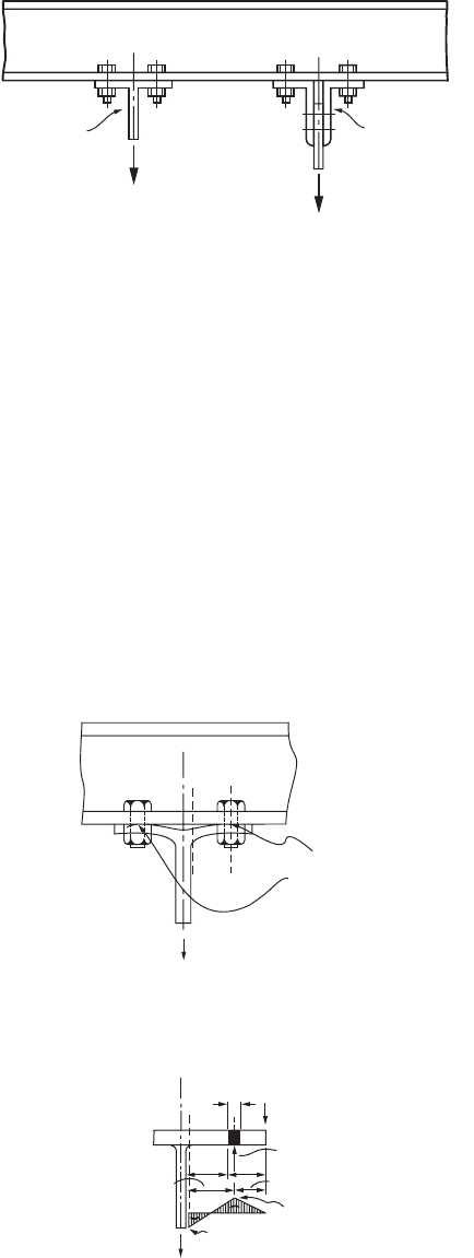
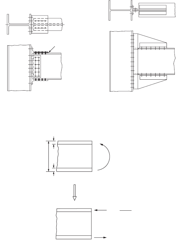
Bolted Hanger-Type Connections
A typical hanger connection is shown in Fig. 48.14. In the design of such connections, the designer must
take into account the effect of prying action. Prying action results when flexural deformation occurs in
the tee flange or angle leg of the connection (Fig. 48.15). The prying action tends to increase the tensile
force, called prying force, in the bolts. To minimize the effect of prying, the fasteners should be placed
as close to the tee stem or outstanding angle leg as the wrench clearance will permit (see tables on entering
and tightening clearances in Volume II, Connections, of the AISC-LRFD manual [AISC, 1992]). In
addition, the flange and angle thicknesses should be proportioned so that the full tensile capacities of
the bolts can be developed.
FIGURE 48.14 Hanger connections.
FIGURE 48.15 Prying action in hanger connections.
Double Angle
T
EE
12
12
Prying Action
in Bolts
d
Q
a
b
a′b′
B
C
M
2
M
1
© 2003 by CRC Press LLC
48-66 The Civil Engineering Handbook, Second Edition
Two failure modes can be identified for hanger-type connections: formation of plastic hinges in the
tee flange or angle leg at cross sections 1 and 2, and tensile failure of the bolts when the tensile force,
including prying action B
c
(=B + Q), exceeds the tensile capacity of bolt B. Since the determination of
the actual prying force is rather complex, the design equation for the required thickness for the tee flange
or angle leg is semiempirical in nature. It is given by the following:
If ASD is used:
(48.109)
where T is the tensile force per bolt due to the service load, exclusive of initial tightening and prying
force (kips).
The other variables are as defined in Eq. (48.110) below, except that B in the equation for a¢ is defined
as the allowable tensile force per bolt. A design is considered satisfactory if the thickness of the tee flange
or angle leg t
f
exceeds t
req’d
and B > T.
If LRFD is used:
(48.110)
where f
b
= 0.90
T
u
= the factored tensile force per bolt, exclusive of initial tightening and prying force (kips)
p = the length of flange tributary to each bolt measured along the longitudinal axis of the tee
or double-angle section (in.)
d = the ratio of the net area at the bolt line to the gross area at the angle leg or stem face, (p – d¢)/p
d ¢ = the diameter of bolt hole, bolt diameter + 1/8 in.
a¢ = ; (if a¢ is less than zero, use a¢ = 1)
B = the design tensile strength of one bolt, fF
t
A
b
(kips) (fF
t
is given in Table 48.11 and A
b
is
the nominal diameter of the bolt)
a¢ = a + d/2
b¢ = b – d/2
a = the distance from the bolt centerline to the edge of the tee flange or angle leg, but not
more than 1.25b (in.)
b = the distance from the bolt centerline to the face of the tee stem or outstanding leg (in.).
A design is considered satisfactory if the thickness of the tee flange or angle leg t
f
exceeds t
req’d
and B >
T
u
. Note that if t
f
is much larger than t
req’d
, the design will be too conservative. In this case, a¢ should be
recomputed using the equation
(48.111)
As before, the value of a¢ should be limited to the range 0 £ a¢ £ 1. This new value of a¢ is to be used
in Eq. (48.110) to recalculate t
req’d
.
t
T b
pF +
r eqd
y
¢
=
¢
¢
()
8
1 da
t
Tb
pF +
r eqd
u
by
¢
=
¢
¢
()
4
1fda
BT a b
BT a b
u
u
-
()
¢¢
()
--
()
¢¢
()
[]
£
1
11
1
d
¢
=
¢
-
È
Î
Í
Í
˘
˚
˙
˙
a
df
1
4
1
2
Tb
pt F
u
bfy
© 2003 by CRC Press LLC
Design of Steel Structures 48-67
Bolted Bracket-Type Connections
Figure 48.16 shows three commonly used bracket-type connec-
tions. The bracing connection shown in Fig. 48.16a should pref-
erably be designed so that the line of action of the force will pass
through the centroid of the bolt group. It is apparent that the bolts
connecting the bracket to the column flange are subjected to com-
bined tension and shear. As a result, the combined tensile–shear
capacities of the bolts should be checked in accordance with Eq.
(48.107) in ASD or Eq. (48.108) in LRFD. For simplicity, f
v
and f
t
are to be computed assuming that both the tensile and shear com-
ponents of the force are distributed evenly to all bolts. In addition
to checking for the bolt capacities, the bearing capacities of the
column flange and the bracket should also be checked. If the axial
component of the force is significant, the effect of prying should
also be considered.
In the design of the eccentrically loaded connections shown in
Fig. 48.16b, it is assumed that the neutral axis of the connection
lies at the center of gravity of the bolt group. As a result, the bolts
above the neutral axis will be subjected to combined tension and
shear, so Eq. (48.107) or (48.108) needs to be checked. The bolts
below the neutral axis are subjected to shear only, so Eq. (48.104)
or (48.105) applies. In calculating f
v
, one can assume that all bolts
in the bolt group carry an equal share of the shear force. In calcu-
lating f
t
, one can assume that the tensile force varies linearly from
a value of zero at the neutral axis to a maximum value at the bolt
farthest away from the neutral axis. Using this assumption, f
t
can
be calculated from the equation Pey/I, where y is the distance from
the neutral axis to the location of the bolt above the neutral axis and I = SA
b
y
2
is the moment of inertia
of the bolt areas, with A
b
being the cross-sectional area of each bolt. The capacity of the connection is
determined by the capacities of the bolts and the bearing capacity of the connected parts.
For the eccentrically loaded bracket connection shown in Fig. 48.16c, the bolts are subjected to shear.
The shear force in each bolt can be obtained by adding vectorally the shear caused by the applied load
P and the moment P
c
o
. The design of this type of connections is facilitated by the use of tables contained
in the AISC-ASD and AISC-LRFD manuals [AISC, 1989, 2001].
In addition to checking for bolt shear capacity, one needs to check the bearing and shear rupture
capacities of the bracket plate to ensure that failure will not occur in the plate.
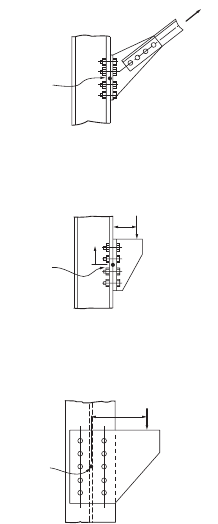
Bolted Shear Connections
Shear connections are connections designed to resist shear force only. They are used in type 2 or type 3
construction in ASD and in type PR construction in LRFD. These connections are not expected to provide
appreciable moment restraint to the connection members. Examples of these connections are shown in
Fig. 48.17. The framed beam connection shown in Fig. 48.17a consists of two web angles that are often
shop-bolted to the beam web and then field-bolted to the column flange. The seated beam connection
shown in Fig. 48.17b consists of two flange angles often shop-bolted to the beam flange and field-bolted
to the column flange. To enhance the strength and stiffness of the seated beam connection, a stiffened
seated beam connection, shown in Fig.48.17c, is sometimes used to resist large shear force. Shear con-
nections must be designed to sustain appreciable deformation, and yielding of the connections is
expected. The need for ductility often limits the thickness of the angles that can be used. Most of these
connections are designed with angle thicknesses not exceeding 5/8 in.
FIGURE 48.16 Bolted bracket-type
connections.
Centroid of
Bolt Group
Centroid of
Bolt Group
Centroid of
Bolt Group
y
e
P
u
P
u
P
u
x
0
© 2003 by CRC Press LLC
48-68 The Civil Engineering Handbook, Second Edition
The design of the connections shown in Fig. 48.17 is facilitated by the use of design tables contained
in the AISC-ASD and AISC-LRFD manuals. These tables give design loads for the connections with
specific dimensions based on the limit states of bolt shear, the bearing strength of the connection, the
bolt bearing with different edge distances, and the block shear (for coped beams).
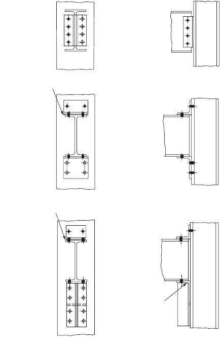
Bolted Moment-Resisting Connections
Moment-resisting connections are connections designed to resist both moment and shear. They are used
in type 1 construction in ASD and in type FR construction in LRFD. These connections are often referred
to as rigid or fully restrained connections, as they provide full continuity between the connected members
and are designed to carry the full factored moments. Figure 48.18 shows some examples of moment-
resisting connections. Additional examples can be found in the AISC-ASD and AISC-LRFD manuals and
in Chapter 4 of the AISC manual on connections [AISC, 1992].
Design of Moment-Resisting Connections
An assumption used quite often in the design of moment connections is that the moment is carried
solely by the flanges of the beam. The moment is converted to a couple F
f
given by F
f
= M/(d – t
f
) acting
on the beam flanges, as shown in Fig. 48.19.
FIGURE 48.17 Bolted shear connections: (a) bolted framed beam connection, (b) bolted seated beam connection,
(c) bolted stiffened seated beam connection.
(a) Bolted Framed Beam Connection
(b) Bolted Seated Beam Connection
(c) Bolted Stiffened Seated Beam Connection
Use shims as required
Stiffeners
fitted to
bear
Use shims as required
© 2003 by CRC Press LLC
Design of Steel Structures 48-69
The design of the connection for moment is considered satisfactory if the capacities of the bolts and
connecting plates or structural elements are adequate to carry the flange force F
f
. Depending on the
geometry of the bolted connection, this may involve checking: (1) the shear and tensile capacities of the
bolts, (2) the yield and fracture strengths of the moment plate, (3) the bearing strength of the connected
parts, and (4) the bolt spacing and edge distance, as discussed in the foregoing sections.
As for shear, it is common practice to assume that all the shear resistance is provided by the shear
plates or angles. The design of the shear plates or angles is governed by the limit states of bolt shear, the
bearing of the connected parts, and shear rupture.
If the moment to be resisted is large, the flange force may cause bending of the column flange or local
yielding, crippling, or buckling of the column web. To prevent failure due to bending of the column
flange or local yielding of the column web (for a tensile F
f
), as well as local yielding, crippling, or buckling
of the column web (for a compressive F
f
), column stiffeners should be provided if any one of the
conditions discussed in Section 48.5 under Criteria for Concentrated Loads is violated.
FIGURE 48.18 Bolted moment connections.
FIGURE 48.19 Flange forces in moment connections.
+++
+
+
+
+
+
+
+
+
+
+
+
+
+
+++
++++++
+ + + + + +
+ + + + + +
Use shims as required
(a) (b)
t
f
d
M
u
t
f
=
F
f
M
u
d − t
f
F
f
© 2003 by CRC Press LLC
48-70 The Civil Engineering Handbook, Second Edition
Following is a set of guidelines for the design of column web stiffeners [AISC, 1989, 2001]:
1. If local web yielding controls, the area of the stiffeners (provided in pairs) shall be determined
based on any excess force beyond that which can be resisted by the web alone. The stiffeners need
not extend more than one half the depth of the column web if the concentrated beam flange force
F
f
is applied at only one column flange.
2. If web crippling or compression buckling of the web controls, the stiffeners shall be designed as
axially loaded compression members (see Section 48.4). The stiffeners shall extend the entire depth
of the column web.
3. The welds that connect the stiffeners to the column shall be designed to develop the full strength
of the stiffeners.
In addition, the following recommendations are given:
1. The width of the stiffener plus one half of the column web thickness should not be less than one
half the width of the beam flange or the moment connection plate that applies the force.
2. The stiffener thickness should not be less than one half the thickness of the beam flange.
3. If only one flange of the column is connected by a moment connection, the length of the stiffener
plate does not have to exceed one half the column depth.
4. If both flanges of the column are connected by moment connections, the stiffener plate should
extend through the depth of the column web, and welds should be used to connect the stiffener
plate to the column web with sufficient strength to carry the unbalanced moment on opposite
sides of the column.
5. If column stiffeners are required on both the tension and compression sides of the beam, the size
of the stiffeners on the tension side of the beam should be equal to that on the compression side
for ease of construction.
In lieu of stiffener plates, a stronger column section should be used to preclude failure in the column
flange and web.
For a more thorough discussion of bolted connections, see the book by Kulak et al. [1987]. Examples
on the design of a variety of bolted connections can be found in the AISC-LRFD manual [AISC, 2001]
and in the AISC manual on connections [AISC, 1992].
Welded Connections
Welded connections are connections whose components are joined together primarily by welds. The four
most commonly used welding processes are discussed in Section 48.1 under Structural Fasteners. Welds
can be classified according to:
• the types of welds: groove, fillet, plug, and slot
• the positions of the welds: horizontal, vertical, overhead, and flat
• the types of joints: butt, lap, corner, edge, and tee
Although fillet welds are generally weaker than groove welds, they are used more often because they
allow for larger tolerances during erection than groove welds. Plug and slot welds are expensive to make
and do not provide much reliability in transmitting tensile forces perpendicular to the faying surfaces.
Furthermore, quality control of such welds is difficult because inspection of the welds is rather arduous.
As a result, plug and slot welds are normally used just for stitching different parts of the members together.
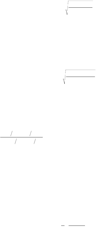
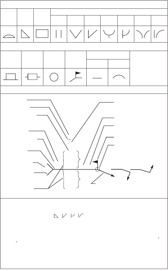
Welding Symbols
A shorthand notation giving important information on the location, size, length, etc. for various types
of welds was developed by the American Welding Society [AWS, 1987] to facilitate the detailing of welds.
This system of notation is reproduced in Fig. 48.20.
© 2003 by CRC Press LLC
Design of Steel Structures 48-71
Strength of Welds
In ASD, the strength of welds is expressed in terms of allowable stress. In LRFD, the design strength of
welds is taken as the smaller of the design strength of the base material fF
BM
(expressed as a function of
the yield stress of the material) and the design strength of the weld electrode fF
W
(expressed as a function
of the strength of the electrode F
EXX
). These allowable stresses and design strengths are summarized in
Table 48.18 [AISC, 1989, 1999]. When using ASD, the computed stress in the weld shall not exceed its
allowable value. When using LRFD, the design strength of welds should exceed the required strength,
obtained by dividing the load to be transmitted by the effective area of the welds.
FIGURE 48.20 Basic weld symbols.
BASIC WELD SYMBOLS
SUPPLEMENTARY WELD SYMBOLS
STANDARD LOCATION OF ELEMENTS OF A WELDING SYMBOL
BACK
BACKING SPACER
WELD ALL
AROUND
FIELD
WELD
CONTOUR
FLUSH CONVEX
For other basic and
supplementary weld
symbols, see
AWS A2.4-79
FILLET
PLUG
OR
SLOT
SQUARE V BEVEL U J
FLARE
V
FLARE
BEVEL
Finish symbol
Contour symbol
Root opening, depth
of filling for plug
and slot welds
Effective throat
Reference line
Specification, process
or other reference
Tail (omitted when
reference is not used)
Basic weld symbol
or detail reference
Arrow connects reference line to arrow side
of joint. Use break as at A or B to signify
that arrow is pointing to the grooved
member in bevel or J-grooved joints.
Weld-all-around symbol
Field weld symbol
Pitch (c. to c. spacing)
of welds in inches
Length of weld in inches
Groove angle or included
angle of countersink
for plug welds
A
L@P
T
R
(Both sides)
(Arrow
side)
(Other
side)
S(E)
F
A
B
Depth of preparation
or size in inches
Note:
Size, weld symbol, length of weld and spacing must read in that order from left to right along the
reference line. Neither orientation of reference line nor location of the arrow alters this rule.
The perpendicular leg of weld symbols must be at left.
Arrow and Other Side welds are of the same size unless otherwise shown. Dimensions of fillet
welds must be shown on both the Arrow Side and the Other Side Symbol.
The point of the field weld symbol must point toward the tail.
Symbols apply between abrupt changes in direction of welding unless governed by the all
around symbol or otherwise dimensioned.
These symbols do not explicitly provide for the case that frequently occurs in structural work,
where duplicate material (such as stiffeners) occurs on the far side of a web or gusset plate. The
fabricating industry has adopted this convention: that when the billing of the detail material discloses
the existence of a member on the far side as well as on the near side, the welding shown for the near
side shall be duplicated on the far side.
,,,
Groove or Butt
© 2003 by CRC Press LLC

48-72 The Civil Engineering Handbook, Second Edition
Effective Area of Welds
The effective area of groove welds is equal to the product of the width of the part joined and the effective
throat thickness. The effective throat thickness of a full-penetration groove weld is taken as the thickness
of the thinner part joined. The effective throat thickness of a partial-penetration groove weld is taken as
TA BLE 48.18 Strength of Welds
Types of Weld and
Stress
a
Material
ASD
Allowable Stress
LRFD
fF
BM
or fF
W
Required Weld Strength Level
b,c
Full-Penetration Groove Weld
Te nsion normal to
effective area
Base Same as base metal 0.90F
y
“Matching” weld must be used
Compression normal
to effective area
Base Same as base metal 0.90F
y
We ld metal with a strength level equal
to or less than that of the “matching”
weld metal must be used
Te nsion or
compression parallel
to axis of weld
Base Same as base metal 0.90F
y
Shear on effective area Base
We ld electrode
0.30 ¥ nominal
tensile strength of
weld metal
0.90[0.60F
y
]
0.80[0.60F
EXX
]
Partial-Penetration Groove Welds
Compression normal
to effective area
Base Same as base metal 0.90F
y
We ld metal with a strength level equal
to or less than that of the “matching”
weld metal may be used
Te nsion or
compression parallel
to axis of weld
d
Shear parallel to axis of
weld
Base
We ld electrode
0.30 ¥ nominal
tensile strength of
weld metal
0.75[0.60F
EXX
]
Te nsion normal to
effective area
Base
We ld electrode
0.30 ¥ nominal
tensile strength of
weld metal £0.18 ¥
yield stress of base
metal
0.90F
y
0.80[0.60F
EXX
]
Fillet Welds
Stress on effective area Base
We ld electrode
0.30 ¥ nominal
tensile strength of
weld metal
0.75[0.60F
EXX
]Weld metal with a strength level equal
to or less than that of “matching”
weld metal may be used
Te nsion or
compression parallel
to axis of weld
d
Base Same as base metal 0.90F
y
Plug or Slot Welds
Shear parallel to faying
surfaces (on effective
area)
Base
We ld electrode
0.30 ¥ nominal
tensile strength of
weld metal
0.75[0.60F
EXX
]Weld metal with a strength level equal
to or less than that of “matching”
weld metal may be used
a
See below for effective area.
b
See AWS D1.1 for “matching” weld material.
c
We ld metal one strength level stronger than “matching” weld metal will be permitted.
d
Fillet welds and partial-penetration groove welds joining component elements of built-up members, such as flange-to-web
connections, may be designed without regard to the tensile or compressive stress in these elements parallel to the axis of the
welds.
© 2003 by CRC Press LLC
Design of Steel Structures 48-73
the depth of the chamfer for J, U, bevel, or V (with bevel ≥60°) joints, and it is taken as the depth of the
chamfer minus 1/8 in. (3 mm) for bevel or V joints if the bevel is between 45° and 60°. For flare bevel-
groove welds the effective throat thickness is taken as 5R/16, and for flare V-groove welds the effective
throat thickness is taken as R/2 (or 3R/8 for the GMAW process when R ≥ 1 in.). R is the radius of the
bar or bend.
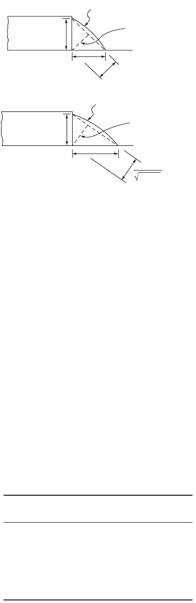
The effective area of fillet welds is equal to the product of the length of the fillets, including returns,
and the effective throat thickness. The effective throat thickness of a fillet weld is the shortest distance
from the root of the joint to the face of the diagrammatic weld, as shown in Fig. 48.21. Thus, for an
equal leg fillet weld, the effective throat is given by 0.707 times the leg dimension. For a fillet weld made
by the SAW process, the effective throat thickness is taken as the leg size (for 3/8-in. or 9.5-mm and
smaller fillet welds) or as the theoretical throat plus 0.11 in. or 3 mm (for fillet welds over 3/8 in. or
9.5 mm). A larger value for the effective throat thickness is permitted for welds made by the SAW process
to account for the inherently superior quality of such welds.
The effective area of plug and slot welds is taken as the nominal cross-sectional area of the hole or
slot in the plane of the faying surface.
Size and Length Limitations of Welds
To ensure effectiveness, certain size and length limitations are imposed for welds. For partial-penetration
groove welds, minimum values for the effective throat thickness are given in Table 48.19.
FIGURE 48.21 Effective throat of fillet welds.
TA BLE 48.19 Minimum Effective Throat Thickness
for Partial-Penetration Groove Welds (in.)
Thickness of the Thicker
Part Joined, t
Minimum Effective
Throat Thickness
t £ 1/4
1/4 < t £ 1/2
1/2 < t £ 3/4
3/4 < t £ 1½
1½ < t £ 2¼
2¼ < t £ 6
>6
1/8
3/16
1/4
5/16
3/8
1/2
5/8
Note: 1 in. = 25.4 mm
a
a
Weld Face
Theoretical Throat
0.707a
a
b
Weld Face
Theoretical Throat
ab
a
2
+b
2
© 2003 by CRC Press LLC