Wai-Fah Chen.The Civil Engineering Handbook
Подождите немного. Документ загружается.

51
-10
The Civil Engineering Handbook, Second Edition
rigid frame action derived from the haunched connections can resist lateral loads due to wind without
the need for vertical bracing. Haunched beams offer higher strength and stiffness during the steel erection
stage, thus making this type of system particularly attractive for long-span construction. However,
haunched connections behave differently under positive and negative moments, as the connection con-
figuration is asymmetrical about the axis of bending.
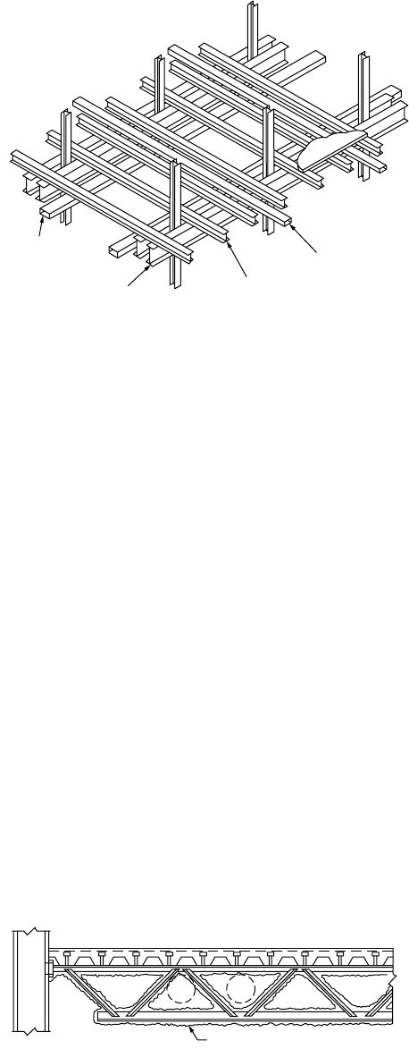
Parallel Beam System
This system consists of two main beams, with secondary beams running over the top of the main beams
(see Fig. 51.14). The main beams are connected to either side of the column. They can be made continuous
over two or more spans supported on stubs and attached to the columns. This will help in reducing the
construction depth and thus avoid the usual beam-to-column connections. The secondary beams are
designed to act compositely with the slab and may also be made to span continuously over the main
beams. The need to cut the secondary beams at every junction is thus avoided. The parallel beam system
is ideally suited for accommodating large service ducts in orthogonal directions (Fig. 51.14). Small savings
in steel weight are expected from the continuous construction because the primary beams are noncom-
posite. However, the main beam can be made composite with the slab by welding beam stubs to the top
flange of the main beam and connecting them to the concrete slab through the use of shear studs (see
Stub Girder System below). The simplicity of connections and ease of fabrication make this long-span
beam option particularly attractive.
Composite Trusses
Composite truss systems can be used to accommodate large services. Although the cost of fabrication is
higher in material cost, truss construction can be cost-effective for very long spans when compared with
other structural schemes. One disadvantage of the truss configuration is that fire protection is labor-
intensive, and sprayed protection systems cause a substantial mess to the services that pass through the
web opening (see Fig. 51.15).
FIGURE 51.14
Parallel composite beam system.
FIGURE 51.15
Composite truss.
Service ducts
Non-composite dual beam
Composite secondary beams
Service ducts
Fire protection
© 2003 by CRC Press LLC
Composite Steel–Concrete Structures
51
-11
The resistance of a composite truss is governed by: (1) yielding of the bottom chord, (2) crushing of the
concrete slab, (3) failure of the shear connectors, (4) buckling of the top chord during construction,
(5) buckling of web members, and (6) instability occurring during and after construction. To avoid brittle
failures, ductile yielding of the bottom chord is the preferred failure mechanism. Thus the bottom chord
should be designed to yield prior to crushing of the concrete slab. The shear connectors should have sufficient
capacity to transfer the horizontal shear between the top chord and the slab. During construction, adequate
plan bracing should be provided to prevent top chord buckling. When considering composite action, the
top steel chord is assumed not to participate in the moment resistance of the truss, since it is located very
near to the neutral axis of the composite truss and thus contributes very little to the flexural capacity.
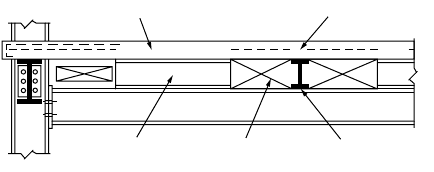
Stub Girder System
The stub girder system involves the use of short beam stubs, which are welded to the top flange of a
continuous, heavier bottom girder member and connected to the concrete slab through the use of shear
studs. Continuous transverse secondary beams and ducts can pass through the openings formed by the
beam stub. The natural openings in the stub girder system allow the integration of structural and service
zones in two directions (Fig. 51.16), permitting story height reduction, compared with some other
structural framing systems.
Ideally, stub girders span about 12 to 15 m, in contrast to the conventional floor beams, which span
about 6 to 9 m. The system is therefore very versatile, particularly with respect to secondary framing
spans, with beam depths being adjusted to the required structural configuration and mechanical require-
ments. Overall girder depths vary only slightly, by varying the beam and stub depths. The major disad-
vantage of the stub girder system is that it requires temporary props at the construction stage, and these
props have to remain until the concrete has gained adequate strength for composite action. However, it
is possible to introduce an additional steel top chord, such as a T section, which acts in compression to
develop the required bending strength during construction. For span lengths greater than 15 m, stub
girders become impractical, because the slab design becomes critical.
In the stub girder system, the floor beams are continuous over the main girders and splices at the
locations near the points of inflection. The sagging moment regions of the floor beams are usually
designed compositely with the deck slab system, to produce savings in structural steel as well as provide
stiffness. The floor beams are bolted to the top flange of the steel bottom chord of the stub girder, and
two shear studs are usually specified on each floor beam, over the beam–girder connection, for anchorage
to the deck slab system. The stub girder may be analyzed as a Vierendeel girder, with the deck slab acting
as a compression top chord, the full-length steel girder as a tensile bottom chord, and the steel stubs as
vertical web members or shear panels.
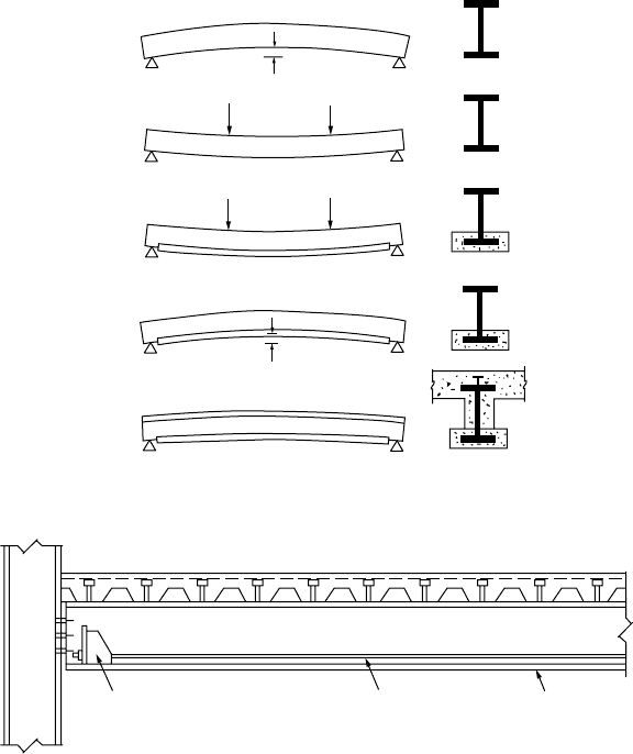
Prestressed Composite Beams
Prestressing of steel girders is carried out such that the concrete slab remains uncracked under working
loads and the steel is utilized fully in terms of stress in the tension zone of the girder.
Prestressing of steel beams can be carried out using a precambering technique, as depicted in Fig. 51.17.
First, a steel girder member is prebent (Fig. 51.17(a)); then it is subjected to preloading in the direction
against the bending curvature until the required steel strength is reached (Fig. 51.17(b)). Second, the
FIGURE 51.16
Stub girder system.
TTTTTTTT T TT
Shear connectorShear connector
Stub welded to
bottom chord
Service zone
Composite
secondary beam
© 2003 by CRC Press LLC
51
-12
The Civil Engineering Handbook, Second Edition
lower flange of the steel member, which is under tension, is encased in a reinforced concrete chord
(Fig. 51.17(c)). The composite action between the steel beam and the concrete slab is developed by
providing adequate shear connectors at the interface. When the concrete gains adequate strength, the
steel girder is prestressed by stress-relieving the precompressed tension chord (Fig. 51.17(d)). Further
composite action can be achieved by supplementing the girder with
in situ
or prefabricated reinforced
concrete slabs; this will produce a double composite girder (Fig. 51.17(e)).
The main advantage of this system is that the steel girders are encased in concrete on all sides: no
corrosion or fire protection is required for the sections. The entire process of precambering and pre-
stressing can be performed and automated in a factory. During construction, the lower concrete chord
cast in the works can act as formwork. If the distance between two girders is large, precast planks can be
supported by the lower concrete chord, which is used as a permanent formwork.
Prestressing can also be achieved by using tendons that can be attached to the bottom chord of a steel
composite truss or the lower flange of a composite girder to enhance the load-carrying capacity and
stiffness of long-span structures (Fig. 51.18). This technique is popular for bridge construction in Europe
and the U.S., but it is less common for building construction.
Composite Column Systems
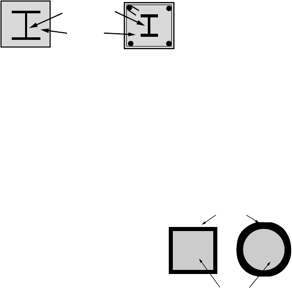
Composite columns have been used for over 100 years, with steel-encased sections similar to that shown
in Fig. 51.19(a) being incorporated in multistory buildings in the United States during the late nineteenth
FIGURE 51.17
Process of prestressing using precambering technique.
FIGURE 51.18
Prestressing of composite steel girders with tendons.
a)
b)
c)
d)
e)
Steel sectionTendons
Anchor
© 2003 by CRC Press LLC
Composite Steel–Concrete Structures
51
-13
century [1]. The initial application of composite columns was for fire rating requirements of the steel
section [3]. Later developments saw the composite action fully utilized for strength and stability [4,5].
Composite action in columns utilizes the favorable tensile and compressive characteristics of the steel
and concrete, respectively. These types of columns are still in use today where steel sections are used as
erection columns, with reinforced concrete cast around them as shown in Fig. 51.19(b). One major
benefit of this system has been the ability to achieve higher steel percentages than conventional reinforced
concrete structures, and the steel erection column allows rapid construction of steel floor systems in
steel-framed buildings.
Concrete-filled steel columns, as illustrated in Fig. 51.20, were
developed much later during the last century but are still based on
the fundamental principle that steel and concrete are most effective
in tension and compression, respectively. The major benefits also
include constructability issues, whereby the steel section acts as
permanent and integral formwork for the concrete. These columns
were initially researched during the 1960s, with the use of hot-rolled
steel sections filled with concrete considered in Neogi et al. [6] and
Knowles and Park [7,8]. These sections, while studied extensively,
were essentially expensive, as the steel section itself was designed to
be hollow, thus requiring large steel plate thicknesses. This lack of
constructional economy has seen the use of concrete-filled steel
columns limited in their application throughout the world. Furthermore, restrictive cross section sizes
have rendered them unsuitable for application in tall buildings, where demand on axial strength is high.
Japan has been an exception to the rule in regard to the application of concrete-filled steel columns.
Widespread use of thick steel tubes or boxes has been invoked to provide confinement for the concrete
and thus achieve greater ductility, which is desirable for cyclic loading experienced during an earthquake.
The use of concrete-filled steel columns was initially justified after the Great Kanto Earthquake in 1923,
when it was found that existing composite structures were relatively undamaged. This has resulted in
more than 50% of the building structures of over five stories in Japan being framed with composite
steel–concrete columns, as described by Wakabayashi [9].
Recently in Australia, Singapore, and other developed nations, concrete-filled steel columns have
experienced a renaissance in their use. The major reasons for this renewed interest are the savings in
construction time, which can be achieved with this method. The major benefits include:
•The steel column acts as permanent and integral
formwork
.
•The steel column provides external
reinforcement
.
•The steel column
supports
several levels of construction prior to concrete being pumped.
A comparison of typical costs of column construction has been compiled by Australian consulting
engineers, Webb and Peyton [10], and this is summarized in Table 51.1. This reveals the competitive
nature of the concrete- filled steel column with or without reinforcement when compared with conven-
tional reinforced concrete columns for buildings over 30 levels. This statistic will be more favorable for
concrete-filled steel columns in buildings of over 50 stories, which are becoming common in many densely
populated cities throughout the world [2].
FIGURE 51.19
Encased composite sections.
Steel section
Concrete
(a) Encased strut
(b) Erection column
FIGURE 51.20 Concrete-filled steel
columns.
Steel section
Concrete
© 2003 by CRC Press LLC
51
-14
The Civil Engineering Handbook, Second Edition
A considerable amount of research has been conducted on this form of column construction, and the
main objective has been to reduce the steel plate thickness. The optimization of the steel thickness requires
a clear understanding of the behavior during all stages of loading. These aspects will be outlined in this
chapter, together with reference to international codes, where design guidance can be provided. In
particular, attention is made to fundamental aspects that have not yet been implemented in international
codes and that often affect the performance of these members in practice.
51.3 Material Properties
The principal material properties that need to be considered in composite members include structural
steel, concrete, reinforcing steel, and profiled steel sheeting, as well as the properties of the shear con-
nectors, which are generally stud shear connectors. Each of these materials will be discussed, and typical
pertinent properties used internationally will be described.
Mild Structural Steel
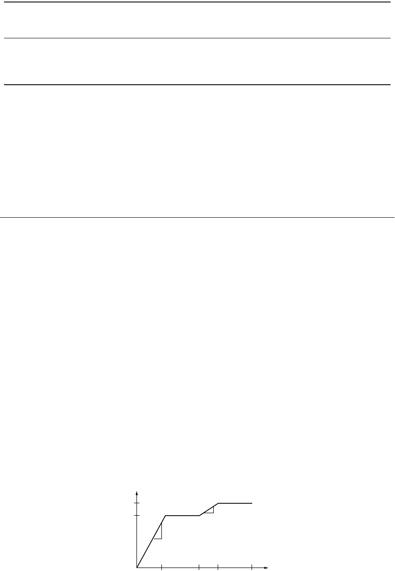
Mild structural steel typical of hot-rolled steel sections exhibits the stress–strain characteristics shown
in Fig. 51.21, which shows an elastic region, followed by a plastic plateau, that extends for approximately
ten times the yield strain. This is then followed by a strain-hardening region leading to a maximum
ultimate stress. The ultimate stress is maintained until the material reaches an ultimate strain, which is
sometimes close to 150 times the yield strain, thus exhibiting extremely ductile behavior.
For structural steel of composite sections, the common steel grades as outlined in Eurocode 4 (EC4)
[11] are given in Table 51.2. The steel sections may be hot or cold rolled. Nominal values of the yield
strength, f
y
, and the ultimate tensile strength, f
u
for structural steel are presented in Table 51.2.
Other material properties related to steel design are:
•Modulus of elasticity, E
a
: 210 kN/mm
2
• Shear modulus, G
a
: E
a
/[2(1 + n
a
)]
•Poisson’s ratio, n
a
: 0.3
•Density, r
a
: 7850 kg/m
3
TA BLE 51.1 Comparison of Column Costs
Type of
Column
Reinforced
Concrete
Concrete with
Steel Erection
Column
Concrete-Encased
Steel Strut
Tub e Filled
with Reinforced
Concrete
Steel Tube
Filled with
Concrete
Full Steel
Column
Relative cost,
10 levels
1.0 1.22 1.53 1.14 1.10 2.27
Relative cost,
30 levels
1.0 1.13 1.85 1.11 1.02 2.61
Source: We bb, J. and Peyton, J.J., in The Institution of Engineers Australian, Structural Engineering Conference, 1990.
FIGURE 51.21 Idealized stress–strain curve for mild structural steel.
f
y
f
u
1
1
E = 210 kN/mm
2
E/33
© 2003 by CRC Press LLC
Composite Steel–Concrete Structures 51-15
High-Strength Steel
The idealized stress–strain curve for high-strength structural steel is shown in Fig. 51.22, which shows
an elastic range and a plastic plateau with no significant strain hardening occurring for the material.
Typical values of yield strengths for high-strength steel are about 700 MPa.
Unconfined Concrete
In composite structures, concrete can be in an unconfined state of stress in compression generally when
used as a slab component of a composite beam. In the modeling of these types of structures, it is important
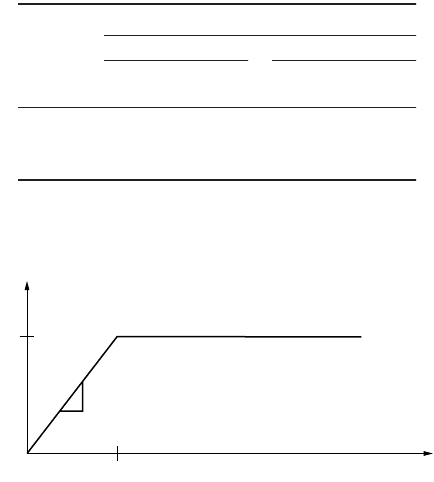
to have a model that represents the concrete stress as a function of strain. The Comite Europeen du
Beton (CEB-FIP) [13] model for stress–strain has been used in the past and is shown in Fig. 51.23. Other
models exist and can be found in most international codes on concrete structures.
Concrete strengths as defined in Eurocode 4 are based on the characteristic cylinder strength, f
ck
,
measured at 28 days. Clause 3.1.2.2 of EC4 also gives the different strength classes and associated cube
strengths, as shown in Table 51.3. The classification of concrete, such as C20/25, refers to the cylinder/cube
concrete strength at the specified age.
For normal-weight concrete the mean tensile strength, f
ctm
, and the secant modulus of elasticity, E
cm
,
for short-term loading are also given in Table 51.3. For lightweight concrete, the secant moduli are
obtained by multiplying the E
cm
value by a factor of (r/2400)
2
, where r is the density of lightweight
concrete.
Confined Concrete
Concrete in composite structures may be confined in a triaxial state of stress when used in applications
such as concrete-filled steel sections. A model to consider this behavior for rectangular or square sections
TABLE 51.2 Nominal Values of Strength of Structural
Steels to BS EN 10025
Nominal
Steel
Grade
Nominal Thickness of Element, t (mm)
t £ 40 mm 40 mm £ t £ 100 mm
f
y
(N/mm
2
)
f
u
(N/mm
2
)
f
y
(N/mm
2
)
f
u
(N/mm
2
)
Fe 360 235 360 215 340
Fe 430 275 430 255 410
Fe 510 355 510 335 490
Source: BS EN 10025, British Standards Institution, London,
1993.
FIGURE 51.22 Idealized stress–strain curve for high strength structural steel.
f
y
ε
y
1
E = 210,000 MPa
© 2003 by CRC Press LLC
51-16 The Civil Engineering Handbook, Second Edition
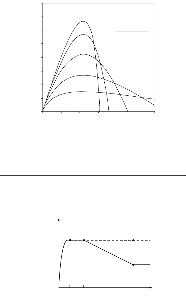
has been developed by Tomii [15]; it is illustrated in Fig. 51.24. Other models also exist for concrete-
filled steel tubes and will be discussed in relation to some of the existing international standards.
Reinforcing Steel
Reinforcing steel is often used as tensile reinforcement in the hogging moment regions of continuous
composite beams, as well as for crack control in the slabs of simply supported composite beams. For
FIGURE 51.23 CEB-FIP stress–strain relationship for concrete. From Comite Europeen du Beton Deformability of
Concrete Structures, Bulletin D’Information, 90, 1970.
TABLE 51.3
Properties of Concrete according to EC2-1990
Strength Class C20/25 C25/30 C30/37 C35/45 C40/50 C45/55 C50/60
f
ck
(N/mm
2
)20253035404550
f
ctm
(N/mm
2
) 2.2 2.6 2.9 3.2 3.5 3.8 4.1
E
cm
(N/mm
2
) 29,000 30,500 32,000 33,500 35,000 36,000 37,000
Source: BS ENV 1992, British Standards Institution, London, 1995.
FIGURE 51.24 Model for confined concrete. From Tomii, M., in paper presented at 3rd International Conference
on Steel–Concrete Composite Structures, ASCCS, Fukuoka, Japan, September 1991.
80
70
60
50
40
30
20
10
0
0 1000 2000 3000 4000 5000 6000
Stress MPa.
Strain (µ_)
b
=
65000(s
o
+
10.0)
−1.085
−
850.0
s
o
e(
a
− 206000e)
s
=
1+
b
e
a
=
39000(s
o
+
7.0)
−0.953
1
1
0.5
B
o
/t ≥ 44
B
o
/t ≤ 22
2.5
7.5
Stress
f
c
/f
cm
Strain ε
c
/ε
cm
© 2003 by CRC Press LLC

Composite Steel–Concrete Structures 51-17
continuous composite beams where large rotational capacity is required, ductile reinforcing steel is
necessary. Eurocode 4 specifies the types of reinforcing steel that may be used in composite structures.
Standardized grades are defined in EN 10080 [16], which is the product standard for reinforcement.
Types of reinforcing steel are classified as follows:
• high (class H) or normal (class N) according to ductility characteristics
• plain smooth or ribbed bars according to surface characteristics
Steel grades commonly used in the construction industry are given in Table 51.4.
Profiled Steel Sheeting
Profiled steel sheeting in composite slabs is often made of cold-formed steel sheeting, which exhibits highly
nonlinear stress–strain characteristics, particularly near the proof stress, s
p
. The Ramberg–Osgood [18]
model is often used to represent the stress–strain characteristics of cold-formed steel. For this model,
stress is represented as a function of strain in the form of
(51.1)
Piecewise linearization is often used in analysis to idealize the stress–strain curves to allow the stress,
s, to be uniquely represented as a function of the strain, e. However, a proof yield stress is usually used
for ultimate strength design.
Shear Connectors
Shear connectors may exist in quite a few varieties, which include headed shear studs, steel angles, and
high-strength friction grip bolts. However, it is the headed shear stud connectors that have seen the
greatest application, and these will be outlined herein. In the design of the shear connection in composite
structures, the designer is mainly interested in the strength that each stud can transfer in shear. Empirical
relationships for the shear resistance of headed shear studs exist in various international codes of practice.
The Australian Standard (AS) AS 2327.1-1996 [19] represents the strength of the shear connectors by
the lesser of one of the following two expressions:
f
vs
= 0.63d
bs
2
f
uc
(51.2)
(51.3)
where d
bs
= the diameter of the shank of the stud
f
uc
= the ultimate strength of the material of the stud
TABLE 51.4 Characteristic Strengths for
Reinforcing Steel according to EC2 and for Modulus
of Elasticity, E
s
according to EC4-1992
Reinforcing
Steel Grades
BS 4449 [17] and
BS 4483 BS EN 10080
f
sk
(N/mm
2
) 460 500
250 Not included
Ductility Not covered Classes H and N
E
s
(N/mm
2
) 210,000 210,000
Source: Eurocode 4, ENV 1994-1-1, European Com-
mittee for Standardization, Brussels, 1992.
e
s
e
s
s
=+
Ê
Ë
Á
ˆ
¯
˜
E
p
p
n
fdfE
vs bs cj c
=
¢
031
2
.
© 2003 by CRC Press LLC

51-18 The Civil Engineering Handbook, Second Edition
f
¢
cj
= the characteristic cylinder strength of the concrete
E
c
= the mean value of the secant modulus of the concrete
Equation (51.2) represents the strength of the shear stud if it fails by fracture of the weld collar, whereas
Eq. (51.3) represents concrete cone failure surrounding the stud. The design shear resistance of studs in
Eurocode 4 for the same failure modes is given by the following:
(51.4)
(51.5)
where d = the diameter of the shank of the stud
f
u
= the ultimate strength of the material of the stud
f
ck
= the characteristic cylinder strength of the concrete
E
cm
= the mean value of the secant modulus of the concrete
h = the overall height of the stud
g
Mv
=a partial safety factor (taken as 1.25 for the ultimate limit state)
a = 0.2[(h/d) + 1] for 3 £ h/d £ 4 and = 1.0 for h/d > 4
51.4 Design Philosophy
Limit States Design
The design philosophy adopted by most international codes throughout the world is one of limit states.
The Australian and North American Standards are limit states design or load resistance factor design
approaches, whereas the Eurocodes are based on partial safety factor approaches.
In general structural design requirements relate to corresponding limit states, so that the design of a
structure that satisfies all the appropriate requirements is termed a limit states design.
Structural design criteria may be determined by the designer, or he or she may use those stated or
implied in design codes. The stiffness design criteria are usually related to the serviceability limit state.
These may include excessive deflections, vibration, noise transmission, member distortion, etc.
Strength limit states pertain to possible methods of failure or overload and include yielding, buckling,
brittle fracture, or fatigue.
The errors and uncertainties involved in the estimation of loads and on the capacity of structures may
be accounted for by using appropriate load factors to increase the nominal loads (S
*
) and capacity
reduction factors (f) to reduce the member strength (R
u
). For strength the generic limit states design
equation can be represented in the form
S* £ fR
u
(51.6)
51.5 Composite Slabs
This section will deal with the design of composite slabs in the composite stage. Composite slabs in the
noncomposite stage are essentially cold-formed steel structures, and the design of these elements is
covered in Chapter 49 “Cold Formed Steel Structures” of this handbook.
Serviceability
Serviceability of composite slabs involves the consideration of the following key issues: deflections,
vibrations, and crack control.
Pfd
Rd u Mv
=
()
08 4
2
. pg
PdfE
Rd ck cm Mv
=
()
029
2
12
. ag
© 2003 by CRC Press LLC

Composite Steel–Concrete Structures 51-19
Deflections
Deflections of composite slabs are treated very similar to deflections of reinforced concrete slabs. However,
this section will reiterate these methods, together with looking at the international standards that already
exist in the design of these elements.
In determining the deflections it is important to be able to calculate the effective second moment of
area of the composite section. A fully cracked section analysis often overestimates the deformations of a
reinforced concrete slab, and subsequently those for a profiled composite slab, for relatively low values
of the applied load above the cracking moment of the section. A tension-stiffening model is therefore
used here that is related to the transformed cracked and uncracked second moments of area, as well as
the ratio of the applied service moment to the cracking moment of the cross section being considered.
The model is based on that of Branson [20], except that the uncracked second moment of area I
u
replaces
this in the following analysis. The effective second moment of area I
eff
is given by
(51.7)
Both BS 5950, Part 4 [21], and ANSI/ASCE 3-91 [22] allow the consideration of a simplified effective
second moment of area as
(51.8)
where I
g
, I
u
, and I
cr
are the gross, uncracked, and cracked second moments of area, respectively. For
determining deflections the transformed section properties are required. In the absence of a more rigorous
analysis, the effects of creep may be taken into account by using modular ratios for the calculation of
flexural stiffness.
(51.9)
where E
a
= the elastic modulus of structural steel; E
c
¢ = an effective modulus of concrete. E
c
¢ = E
cm
for
short-term effects; E
c
¢ = E
cm
/3 for long-term effects; E
c
¢ = E
cm
/2 for other cases.
Vibrations
For long-span composite slabs, which are those types of slabs with deep troughs, it may be necessary to
determine the vibrations of the slab and compare these with acceptable vibrations. Where vibration could
cause discomfort or damage the response of long-span composite floors should be considered using SCI
Publication 076, “Design Guide on the Vibration of Floors” [23].
Crack Control
Crack control requirements are important criteria for composite slabs, particularly when continuous
composite slabs are used. Typical crack control requirements are covered by most international reinforced
concrete structures codes, and these are also covered in Chapter 50 “Structural Concrete Design” of this
handbook.
Strength
Flexural Failure
A rigid plastic assumption is often used to determine the flexural strength of a composite slab. This
method assumes the profiled steel sheeting to be at full yield in tension, with the concrete slab assumed
to be fully crushed in compression, as shown in Fig. 51.25.
IIII
M
M
eff cr u cr
cr
s
=+-
()
Ê
Ë
Á
ˆ
¯
˜
3
I
II
eff
gcr
=
+
2
n
E
E
a
c
=
¢
© 2003 by CRC Press LLC