Wai-Fah Chen.The Civil Engineering Handbook
Подождите немного. Документ загружается.

Plane Surveying 54-15
have horizontal circles marked to read clockwise angles. Transits used to stake out projects typically
include counterclockwise markings to facilitate laying out angles to either side of a reference line. A
deflection angle, also shown in Fig. 54.13, is measured from the prolongation of the backsight line either
left or right to the foresight line. It is commonly used in route centerline surveys.
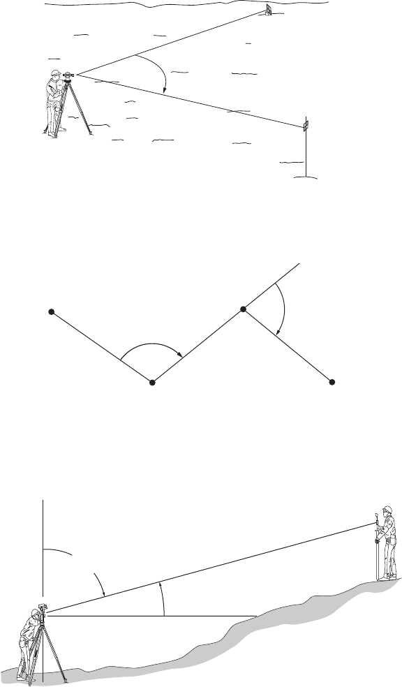
Vertical angles are measured in the vertical plane as shown in Fig. 54.14. An instrument with a vertical
circle graduated to measure vertical angles reads 0˚ when the instrument is level and the telescope is in
the horizontal plane. The vertical angle increases to +90˚ above the horizontal and to –90˚ below the
FIGURE 54.12 Horizontal survey angle.
FIGURE 54.13 Horizontal field angles.
FIGURE 54.14 Vertical field angles.
A
B
0°
30° 14'
Left side
of angle
Right side
of angle
DIRECT
A
C
BD
Prolongation
Clockwise
Angle
Deflection
Angle
Direction of Traversing is A–B–C–D
b
d
Vertical Angle with a transit
Zenith
Zenith Angle with
most theodolites
© 2003 by CRC Press LLC
54-16 The Civil Engineering Handbook, Second Edition
horizontal plane. Many instruments today have vertical circles graduated to measure the zenith angle.
Zero degrees is at the zenith point directly overhead on the vertical axis. The zenith angle will increase
from 0˚ at the zenith to 90˚ at the horizon. The zenith angle is greater than 90˚ if the telescope is pointing
below the horizon. The circle graduations continue to 180˚ at the nadir, to 270˚ at the horizon with the
telescope reversed, and to 360˚ closing the circle at the zenith.
Direction Angles
Direction angles are horizontal angles from a north–south reference meridian to a survey line. Direction
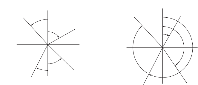
angles that are computed from field angles include bearings and azimuths. A bearing, as shown in Fig. 54.15,
is the acute angle from the reference meridian to the survey line. It always includes the quadrant designation.
An azimuth, as shown in Fig. 54.16, is the angle from the north end of the reference meridian clockwise to
the survey line. It can have a magnitude from 0˚ to 360˚, and a quadrant designation is not necessary.
Several different meridians can be used as a reference for direction. The direction of north at a point
can be defined as any of the following:
•Astronomic north
•Geodetic north
•Magnetic north
•Grid north
•Assumed north
The first three types of meridians converge to their respective north poles on the earth. Therefore,
they do not form the basis for a Cartesian coordinate system to be used for plane surveying. There is
only a small angular difference between astronomic and geodetic north, but astronomic north is typically
taken to be synonymous with the term “true north.”
Magnetic north is the direction of the earth’s magnetic field at a point. A declination angle measured
from the geodetic meridian to the magnetic meridian defines the relationship between the two systems.
However, since the direction of magnetic north changes with time, proper use of magnetic north must
account for variation in the magnetic declination angle.
Grid north is used in plane surveying. The grid should be defined on an appropriate map projection,
such as the state plane coordinate systems available in each state. Then a defined relationship exists
between the geodetic and grid meridians.
Assumed north may be used for preliminary surveys, but it is not recommended for permanent work.
If the stations on the ground are lost or destroyed, the basis of direction is lost and the survey cannot
be retraced.
FIGURE 54.15 Bearing direction angles. FIGURE 54.16 Azimuth direction angles.
NORTH
WEST EAST
SOUTH
N 30° W
N 60
° E
S 45° E
S 30° W
NORTH
330°
215°
145°
35°
© 2003 by CRC Press LLC
Plane Surveying 54-17
Types of Instruments
There are many types of angle-measuring instruments used in surveying and construction. They include
transits, theodolites, digital theodolites, and total stations. Even though the names are different, they look
different, and the operation is slightly different, they all are used for the same purpose — angle mea-
surement and layout.
Although there are a number of differences in the construction and features of transits, optical
theodolites, and digital theodolites, the major difference is in the method of reading angles. Instruments
are often classified according to the smallest interval, or so-called least count, that can be read directly
in the instrument. The least count may range from 1 minute for a construction transit to 0.1 seconds
for a first-order theodolite. Least counts from 10 seconds to 1 second are common in surveying and
engineering instruments. The field engineer should become familiar with the instrument being used on
the project.
Transit
The transit was developed to its present form during the 1800s. It has been used on construction projects
from railroads across the wild west to the skyscrapers of the modern city. A good, solid, and reliable
instrument, the transit is still used by many contractors today. However, optical theodolite technology,
and now digital electronic technology, have passed it by. The major companies who manufactured transits
have dropped them from their product line. They are slower to use than modern instruments, and they
are not as easily adaptable to having an EDMI attached to them. Its major contribution to the field
engineer today is that it is a good tool for learning the fundamentals of angle measurement. Its parts are
exposed, making it easier to see what is going on in the manipulation of the clamps during the angle
measurement process. By understanding the transit, one can easily move on to any other type of angle-
measuring equipment.
Repeating Optical Theodolite
The repeating theodolite contains the same upper and lower clamp system as the transit; however, the
reading of the angle is different because of the optical-reading capability. Optical theodolite is a term that
was originally applied in Europe to instruments similar to the transit. However, as instrument technology
progressed, theodolite became synonymous with a style of instrument that was enclosed, used a magnified
optical system to read the angles, had a detachable tribrach with an optical plummet, used a three-screw
leveling system, and was more precise than the transit. These features have made it much easier to use
than the transit. The better optical theodolites have been “delicate” workhorses since they were introduced.
That is, if they are properly cared for, they seem as though they will last forever because of their excellent
construction and quality materials. However, they must be handled gently and carefully. A typical optical
theodolite may have as many as 20 prisms or lenses as part of the optical angle-reading system. With a
sharp bump, these can get out of alignment, which may render the instrument unusable. As with any
surveying instrument, the theodolite cannot be exposed to inclement weather because of the optical
system.
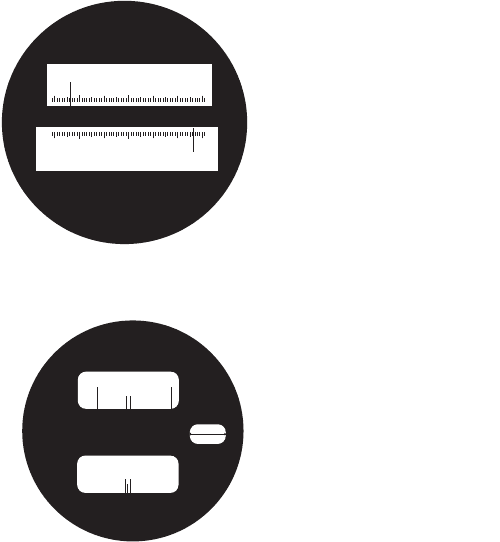
Scale-Reading Optical Theodolite. The typical scale-reading theodolite has a glass circle with a simple
scale that is read directly. The scale is read where it is intersected by the degree readings from the circle.
See Fig. 54.17 for an example scale reading. Simply read the degree that shows up in the window and
observe where the degree index mark intersects the scale. Both the horizontal circle and the vertical circle
are generally observed at the same time.
Micrometer-Reading Optical Theodolite. The micrometer-reading instrument also has a glass circle,
but it does not have a scale. An adjustable micrometer is used to precisely read the circle and subdivide
the degree intervals into minutes and seconds. See Fig. 54.18 for an example micrometer reading. The
operator points the instrument and then uses the micrometer to align the degree index marks. The
readings from the degree window and the micrometer window are added together to obtain the angle.
© 2003 by CRC Press LLC
54-18 The Civil Engineering Handbook, Second Edition
Directional Optical Theodolite
The directional theodolite is different from other instruments because it does not have a lower motion
clamp and tangent screw. Directions (circle readings) are observed and recorded, and then the directions
are subtracted to obtain the angle between the backsight and foresight lines of sight. This type of system
has generally been used only on the most precise instruments. Zero is usually not set on the instrument.
A micrometer is used to optically read the circle. Optical theodolites are excellent instruments, but, just
like the transit, they are being surpassed by the technology of electronics.
Digital Theodolite
Digital electronics has recently entered the area of surveying instruments. Angles are no longer read
optically, they are displayed on a screen in degree, minute, and second format. The micrometer has been
replaced with electronic sensors that determine the angle quickly and precisely. The digital theodolite
has the appearance of an optical theodolite in size and overall shape. The telescope, the clamping system,
the tribrach, and the optical plummet are the same. Only the angle-measuring and -reading system is
different. Digital theodolites are easy to read and fewer reading and recording blunders occur in the field.
Because it is electronically based, the digital theodolite is like other electronic equipment — it either
works or it doesn’t work. If a circuit goes out or the battery is not charged, the instrument is unusable.
Most digital theodolites are designed to be interfaced with top-mounted EDMIs. This essentially has
the impact of turning them into what are commonly called semitotal stations, which measure distances
and angles and can be connected to a data collector for recording measurements. Sighting by both the
instrument telescope and the EDMI scope are accomplished separately with this configuration.
Total Stations
The electronic total station is the ultimate in surveying measurement instruments. It is a combination
digital theodolite and EDMI that allows the user to measure distances and angles electronically, calculate
FIGURE 54.17 Scale angle reading display.
FIGURE 54.18 Micrometer angle reading display.
Hz
270
269
0203040506010
V
0
86
85
20 30 40 50 6010
Vertical angle = 86° 06' 30"
Horizontal angle = 269° 56' 30"
Horizontal angle = 236° 17' 30"
236
Hz
90 91
V
17 24
17 30
17 26
© 2003 by CRC Press LLC
Plane Surveying 54-19
coordinates of points, and attach an electronic field book to collect and record the data. Since the total
station is a combination digital theodolite and EDMI, its cost is quite high compared to a single instru-
ment. However, its capabilities are simply phenomenal in comparison to the way surveyors and engineers
had to measure just a few years ago. Total stations with data collectors are especially effective when a
large number of points are to be located in the field, as in topographic mapping. The data collector can
be used to transfer the points to a computer for final map preparation. Conversely, complex projects can
be calculated on a computer in the office and the data uploaded to the data collector. The data collector
is then taken to the field and connected to the total station, where hundreds of points can be rapidly
established by radial layout methods.
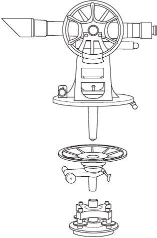
Instrument Components
Although there are differences between the transit,
optical theodolite, and electronic theodolite, the con-
struction and operation of all these instruments is basi-
cally the same. The three major components of any
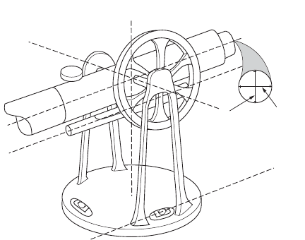
instrument are illustrated, using a transit, in Fig. 54.19.
The upper plate assembly or the alidade, the lower plate
assembly or the horizontal circle, and the leveling head
are shown.
Alidade Assembly
The alidade assembly consists of the telescope, the ver-
tical circle, the vertical clamp and vertical tangent, the
standards or structure that holds everything together,
the verniers, plate bubbles, telescope bubble, and the
upper tangent screw. A spindle at the bottom of the
assembly fits down into a hollow spindle on the hori-
zontal circle assembly.
Horizontal Circle Assembly
The horizontal circle assembly comprises the horizon-
tal circle, the upper clamp that clamps the alidade and
horizontal circle together, and the hollow spindle that
accepts the spindle from the alidade and fits into the
leveling head.
Leveling Head
The leveling head is the foundation that attaches the instrument assemblies to the tripod. It consists of
leveling screws, the lower clamp that clamps the horizontal circle and the leveling head together, and a
threaded bracket for attaching to the tripod.
Fundamental Relationships
All transit or theodolite instruments are designed around the same fundamental relationships and lines.
These lines are shown in Fig. 54.20, again illustrated with a standard transit. The principal relationships
between these lines are described as follows:
•The axis of the plate level(s) should be perpendicular to the vertical axis.
•The line of sight should be perpendicular to the horizontal axis.
•The horizontal axis should be perpendicular to the vertical axis.
•The vertical circle should read 0˚ when the instrument is leveled and the telescope is horizontal.
FIGURE 54.19 Transit or theodolite components.
© 2003 by CRC Press LLC
54-20 The Civil Engineering Handbook, Second Edition
These four relationships are necessary to measure horizontal and vertical angles correctly. If the
instrument will be used as a level, then the following must also be true: The axis of the telescope level
should be parallel to the line of sight. Incorrect instrument adjustment in any of the relationships above
will be readily apparent during field use of the instrument. Less apparent will be errors in the following
relationships:
•The line of sight should be coincident with the telescope optical axis.
•The circles should be mounted concentrically on the axis of rotation.
•The circles should be accurately graduated throughout their circumference.
•The optical plummet should correctly position the instrument vertically over the field station.
•The vertical crosshair should lie in a vertical plane perpendicular to the horizontal axis.
Instrument Operation
The fundamental principle in using any transit or theodolite is the principle of reversion. That is, all
operations should be performed in pairs, once with the telescope in the direct position and again with
the telescope inverted on the horizontal axis or the reverse position. The correct value is the average of
the two observations. Instrument operators should always use the double-centering ability of the instru-
ment to eliminate the instrumental errors listed above. All of the principal instrument adjustment
errors — except the vertical axis not being truly vertical — will be compensated for by averaging direct
and reversed pairs of observations.
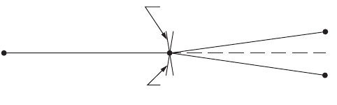
Prolonging a Straight Line
Prolonging a straight line from a backsight station through the instrument station to set a foresight
station is a basic instrument operation that illustrates the principle of reversion. Often referred to as
double centering, the steps to be performed are outlined as follows:
•Set up and level on the instrument station. With the telescope in the direct position, sight to the
backsight station and clamp all horizontal motions.
•Rotate the telescope on the horizontal axis to the reverse position. Sight and set a point P
1
in the
foresight direction as illustrated in Fig. 54.21.
•Revolve the instrument on the vertical axis and sight the backsight station again. The telescope
will be in the reverse position.
FIGURE 54.20 Principal adjustment relationships.
VERTICAL
CROSS-HAIR
HORIZONTAL
AXIS
VERTICAL
AXIS
HORIZONTAL
CROSS-HAIR
AXIS OF
LEVEL TUBE
PLATE LEVEL
AXIS
LINE OF SIGHT
© 2003 by CRC Press LLC
Plane Surveying 54-21
•Rotate the telescope on the horizontal axis to the direct position. Sight and set a point P
2
in the
foresight direction.
•Set the final point, P, on the true extension of the backsight line at the midpoint between P
1
and P
2
.
If the stations are on nearly level terrain, the instrument error apparent in the distance between P
1
and P
2
is the line of sight not being perpendicular to the horizontal axis. When an instrument is severely
out of adjustment, it is inconvenient to use it in the field. The instrument should be cleaned and adjusted
periodically by a qualified instrument service technician.
Horizontal Angles by Repetition
The clamping system is probably the most important feature on an instrument because it determines
the angle measurement procedures that can be used with the instrument. Transits and some optical
theodolites have two horizontal motion clamps. They are commonly called the upper motion and lower
motion. These types of instruments are called repeating instruments since the angle can be repeated and
accumulated on the instrument circle. A procedure for measuring angles by repetition is outlined below.
1. Set the horizontal angle to read zero with the upper clamp and upper tangent screws. This is for
convenience and any initial angle can be used.
2. Point on the backsight station with the telescope in the direct position using the lower motion.
Check the circle reading and record the value in the notes.
3. Loosen the upper clamp (the lower clamp remains fixed), turn the instrument to the foresight
station, and point using the upper motion clamp and upper tangent screw.
4. Note the circle reading. An approximate value of the angle can be obtained from this first turning.
5. Loosen the lower clamp, keeping the angle reading on the circle, and repeat steps 2 and 3. The
number of repetitions must be an even number with half of the turnings with the telescope in the
direct position and half of the turnings with the telescope in the reversed position.
6. With each turning, the circle reading will be incremented by the value of the angle. Thus, the
average angle can be determined quickly by dividing the total angle read from the circle by the
number of times the angle was measured.
Horizontal Angles by Direction
Many theodolites have only the upper horizontal motion clamp and the fine adjustment screw for
pointing. A backsight cannot be made while holding an angle on the circle because there is no lower-
motion fine adjustment for pointing. These types of instruments are called direction instruments since
the circle reading is a clockwise direction angle from an arbitrary orientation of the 0˚ mark on the circle.
A procedure for measuring angles by reading directions is outlined below.
1. Set the horizontal circle to read approximately 0˚ when pointed toward the backsight point with
the telescope in the direct position.
2. Point on the backsight station with the telescope in the direct position using the upper-motion
clamp and tangent screw. Read the horizontal circle and record the value in the notes.
3. Loosen the upper clamp and turn the instrument to point on the foresight station using the upper-
motion clamp and tangent screw. Read the horizontal circle and record the value in the notes.
FIGURE 54.21 Double-centering to prolong a straight line.
Backsight
Horizontal Axis
Direct
Horizontal Axis
Reversed
P
1
P
2
P
© 2003 by CRC Press LLC
54-22 The Civil Engineering Handbook, Second Edition
4. The clockwise angle is the difference between the foresight reading and the backsight reading.
5. Invert the telescope to the reversed position and repeat steps 2, 3, and 4. The circle readings should
be exactly 180˚ from the telescope direct readings if there are no instrument adjustment, pointing,
and reading errors. Of course the direct and reversed angles should agree closely and be averaged.
6. The direct and reversed pointings and the average angle constitute one position. Observe several
positions and average the results to improve the precision of the final average angle. Advance the
horizontal circle approximately between positions in order to distribute the readings around the
circle.
54.5 Plane Survey Computations
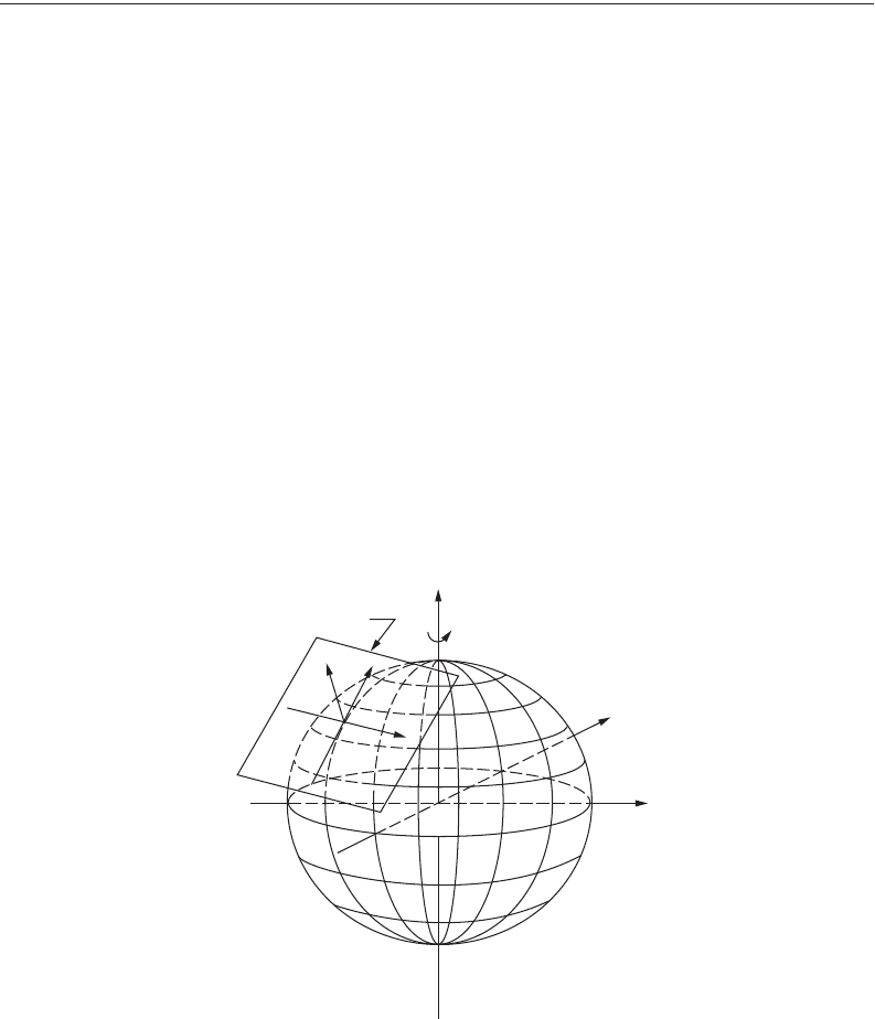
Plane surveys use a three-dimensional Cartesian coordinate system as shown in Fig. 54.22. The horizontal
components of distance, angle, and direction are assumed to be in the plane defined by the X and Y axes.
The vertical components are along the Z axis or “up axis” in a vertical plane perpendicular to the
horizontal XY plane.
Plane surveys referenced to such an orthogonal Cartesian coordinate system ignore the effect of earth
curvature, the fact that the actual level surface is perpendicular everywhere to the direction of gravity.
Such a computation scheme is suitable only for local project surveys of limited extent. Plane survey
computations can be used for horizontal control surveys over a large areal extent if all observations and
positions are properly referenced to a grid system using an appropriate map projection. State plane
coordinate systems, defined for each state, are an example of this technique.
Traverse
A traverse is an efficient and flexible method of field surveying used to connect points of interest and
establish horizontal and/or vertical coordinate reference values for project control. A traverse consists of
interconnected straight lines along a traverse route. The straight lines meet at angle points that must be
permanently marked by a traverse station monument. The length of each line is measured by field survey
and then reduced to the horizontal reference plane. At each traverse station a horizontal angle is measured
that will relate the directions of each line to one another in the horizontal plane. The elevation of each
traverse station may also be determined if required for the purpose of the survey. Elevation can be
FIGURE 54.22 Local tangent plane coordinate system.
Local Plane
Coordinate System
z
u
e
y
x
n
© 2003 by CRC Press LLC

Plane Surveying 54-23
determined by trigonometric leveling as part of the traverse measurements or by differential leveling as
a separate survey operation.
Tr averses are characterized as open or closed. An open traverse has no check on computed direction
or position at the end of the route. It is used only for preliminary and uncontrolled work. Whenever
traverse stations are to be used to control subsequent engineering or surveying work, the route should
be designed to close on the beginning traverse station or to close on another known point of equal or
higher-order accuracy. The closed linear traverse between known control stations is preferred since it
can best detect length measurement errors that affect the scale of a survey.
Tr averse design is influenced by the purpose of the survey and the terrain through which the survey
must progress. The overriding factor in determining where to locate traverse stations is the purpose of
the station. In general, a traverse station becomes a reference system control point that is used for one
or more of the following purposes:
1. Provide control for mapping by field survey or photogrammetric methods.
2. Provide control for construction layout.
3. Locate property boundaries.
4. Connect lines within the traverse and secondary traverses that may be added to the survey network.
The traverse station must be located so that it is accessible for its intended purpose. Secondary to the
purpose of the survey, the traverse station should be located in an area where the monument will be
stable and undisturbed for the intended useful life of the station.
The traverse survey route is flexible and generally follows the path of least resistance so that clear lines
of sight from traverse station to traverse station are obtained. However, several guidelines should be kept
in mind when planning a traverse route. First, avoid lines of sight that pass close to the intervening terrain
between stations where atmospheric refraction will seriously degrade measurement accuracy. Second,
avoid short lines of sight where setup errors and pointing errors can be the dominant measurement error
source. Third, the traverse route should proceed along a generally straight path between terminal stations
of a linear closed traverse. A useful rule of thumb is that the deviation of the route, as measured
perpendicular to the straight-line path, should not exceed approximately one-third of the straight-line
path length.
Accuracy standards for traversing are chosen to match the purpose of the survey. Specifications for
the survey process are then developed to meet the required accuracy standards. For control surveys the
accuracy standards and specifications developed by the Federal Geodetic Control Committee (FGCC)
are often adopted. Surveys may be required to meet first-, second-, or third-order accuracy.
Surveying standards and specifications for surveys intended for other purposes may be available from
a variety of sources, such as state statutes or licensing board rules regulating the type of survey, professional
societies, or the agency contracting for the survey. For example, standards and specifications developed
by ALTA/ACSM are often the requirements adopted for property surveys.
Tr averse computations for local plane surveys are outlined in the following conventional procedure:
1. Draw a complete sketch of the traverse.
2. Compute the angular closure. If angle closure is equal to or less than allowable limit, adjust the
angles; if angle closure is not acceptable, remeasure angles. The allowable closure is typically
specified in the following form:
where
c = allowable error in a series of measurements
k = a value specified for the accuracy order of the survey
n = number of angles measured
3. Compute the direction (azimuths or bearings) of all lines.
Allowable closure ckn==
© 2003 by CRC Press LLC
54-24 The Civil Engineering Handbook, Second Edition
4. Compute the latitude and departure (relative nothing and relative easting components) for each
course. Set up the computations in tabular form.
5. Compute the traverse misclosure.
6. Compute the traverse precision ratio.
7. If the precision ratio is equal to or better than the allowable precision specified for the accuracy
order of the survey, then distribute the error of closure throughout the traverse by an appropriate
rule or by a least-squares adjustment.
8. Compute the coordinates of the traverse stations using the balanced latitudes and departures.
9. Determine the adjusted traverse course lengths and directions using an inverse computation from
the adjusted coordinates or latitudes and departures.
10. Compute the area of a closed loop traverse.
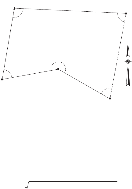
The traverse shown in Fig. 54.23 is used to illustrate conventional plane survey traverse computations.
The measured horizontal distance of each line is given, and horizontal angles are measured as interior
angles on the closed loop traverse. The orientation of the traverse is defined by the azimuth given for
line 1-2. The coordinate system is defined by known coordinates at station of 1000.00N, 500.00E.
1. Draw a complete sketch.
2. Compute the angular closure.
FIGURE 54.23 Sketch of sample traverse.
S 87
°36 E
453.97
231.08
238.54
218
°
24'
97°48'
81°05'
336.92
279.50
72°45'
69
°
53'
1
3
4
2
5
Latitude L
a
cos=
Departure L
a
sin=
c Latitude error()
2
Departure error()
2
+=
Precision
Closure error
Perimeter
--------------------------------
1
?
--==
Field angle closure 97∞48¢ 81∞05¢ 72∞45¢ 218∞24¢ 69∞53¢+++ +()=
52–()180∞–
539∞55¢ 540∞00¢–=
.05¢=
© 2003 by CRC Press LLC