Wai-Fah Chen.The Civil Engineering Handbook
Подождите немного. Документ загружается.


Incinerators 13-27
Polyvinyl chloride 0.20 86.89 10.85 2.06 45.14 5.61 1.56 0.08 0.14 2.06(b) 5419 5431 5556
Linoleum 2.10 64.50 6.60 26.80 48.06 5.34 18.70 0.10 0.40 27.40 4528 4617 6361
Rags 10.00 84.34 3.46 2.20 55.00 6.60 31.20 4.12 0.13 2.45 3833 4251 4358
Te xtiles 15–31 — — — 46.19 6.41 41.85 2.18 0.20 3.17 — 4464 4611
Oils, paints 0 — 16.30 66.85 9.62 5.20 2.00 — 16.30 7444 7444 8889
Va cuum cleaner dirt 5.47 55.68 8.51 30.34 35.69 4.73 20.08 6.25 1.15 32.09 3548 3753 5533
Household dirt 3.20 20.54 6.26 70.00 20.62 2.57 4.00 0.50 0.01 72.30 2039 2106 7583
Municipal Wastes
Street sweepings 20.00 54.00 6.00 20.00 34.70 4.76 35.20 0.14 0.20 25.00 2667 3333 4444
Mineral (c) 2–6 — — — 0.52 0.07 0.36 0.03 0.00 99.02 — 47 —
Metalic (c) 3–11 — — — 4.54 0.63 4.28 0.05 0.01 90.49 — 412 4333
Ashes 10.00 2.68 24.12 63.2 28.0 0.5 0.8 — 0.5 70.2 2089 2318 7778
Fuels
Percent by Weight Higher Heating Value sp. gr.
CHOSNWater Ash kcal/kg kcal/liter kg/l
Fuel Oil
#1, #2 84.7 15.3 nil 0.02 nil nil <0.5 11,061 9,070 0.82
#3 85.8 12.1 nil 1.2 nil nil <0.1 10,528 9,474 0.90
#5 87.9 10.2 nil 1.1 nil 0.05 <1.0 10,139 9,733 0.96
#6 88.3 9.5 nil 1.2 nil 0.05 <2.0 10,000 10,000 1.00
Natural Gas 69.3 22.7 nil nil 0.08 nil nil 13.21 9.435 0.000714
Sources: Properties of waste constituents from Niessen, W. R. 1978. Combustion and Incineration Processes. Marcel Dekker, New York. Properties of fuel oil from Danielson,
1973. Properties of gas from Theodore, 1987.
© 2003 by CRC Press LLC

13-28 The Civil Engineering Handbook, Second Edition
TA BLE 13.3 Enthalpies of Gases
°C N
2
O
2
Air H
2
CO CO
2
H
2
O
Standard Condition: 20°C, 293.16 K (cal/scm)
16 –1.55 –1.55 –1.60 –1.55 –1.60 –1.95 –1.80
21 0.00 0.00 0.00 0.00 0.00 0.00 0.00
25 0.66 0.66 0.69 0.66 0.69 0.83 0.77
38 3.73 3.73 3.68 3.66 3.68 4.76 4.27
93 16.86 17.08 16.81 16.65 16.81 22.24 19.47
149 29.99 30.56 29.94 29.85 30.01 40.72 34.88
204 43.18 44.33 43.28 42.98 43.28 60.06 50.51
260 56.54 58.39 56.70 56.18 56.77 80.25 66.13
316 69.95 72.66 70.26 69.02 70.33 101.09 82.47
371 83.58 87.15 84.03 82.44 84.10 122.57 98.89
427 97.28 101.85 97.94 95.57 98.02 144.62 115.58
482 111.20 116.83 112.00 108.84 112.14 167.17 132.64
538 139.60 147.23 140.69 135.46 140.90 213.62 167.60
649 153.94 162.71 155.24 148.87 155.53 237.45 185.58
704 168.58 178.27 170.01 162.22 170.37 261.57 203.85
760 183.27 193.97 184.86 175.92 185.28 286.05 222.40
816 198.11 209.81 199.91 189.69 200.41 310.95 241.39
871 213.24 225.72 215.18 196.82 215.61 335.93 260.58
927 228.29 241.78 230.31 216.95 230.88 361.19 279.99
982 243.49 257.76 245.72 230.50 246.29 386.80 299.76
1,038 258.76 273.96 261.14 244.28 261.92 412.42 319.73
1,093 274.25 290.30 276.62 258.40 277.55 438.39 340.07
1,149 289.87 306.50 292.25 273.10 293.18 464.37 360.55
1,204 305.29 322.91 308.02 287.95 309.02 490.56 381.24
1,260 321.27 339.46 323.86 302.86 324.79 516.89 402.37
1,316 337.11 356.02 339.70 317.49 340.84 543.43 423.42
1,371 352.88 372.57 355.68 332.54 356.83 569.68 444.89
1,649 433.08 456.42 436.46 406.75 437.60 704.20 554.64
1,927 514.43 541.69 518.38 484.68 519.31 841.13 668.38
2,204 596.35 628.46 600.79 564.88 601.79 980.06 785.12
2,482 678.98 716.58 684.21 645.51 684.82 1119.78 904.15
3,038 846.03 896.76 853.11 813.42 852.54 1402.14 1147.51
3,316 944.21 995.59 938.38 898.69 936.88 1544.85 1271.28
3,593 1014.36 1081.07 1024.22 985.67 1021.44 1688.35 1395.51
°F N
2
O
2
Air H
2
CO CO
2
H
2
O
Standard Condition: 70°F, 530°R (Btu/scf)
60 –0.22 –0.22 –0.22 –0.22 –0.22 –0.27 –0.25
70 0000000
77 0.09 0.09 0.10 0.09 0.10 0.12 0.11
100 0.52 0.52 0.52 0.51 0.52 0.67 0.60
200 2.36 2.39 2.36 2.33 2.36 3.12 2.17
300 4.20 4.28 4.20 4.18 4.21 5.71 4.89
400 6.05 6.21 6.07 6.02 6.07 8.42 7.08
500 7.92 8.18 7.95 7.87 7.96 11.25 9.27
600 9.80 10.18 9.85 9.67 9.86 14.17 11.56
700 11.71 12.21 11.78 11.55 11.79 17.18 13.86
800 13.63 14.27 13.73 13.39 13.74 20.27 16.20
900 15.58 16.37 15.70 15.25 15.72 23.43 18.59
1,000 17.55 18.49 17.70 17.14 17.72 26.65 21.02
1,100 19.56 20.63 19.72 18.98 19.75 29.94 23.49
1,200 21.57 22.80 21.76 20.86 21.80 33.28 26.01
1,300 23.62 24.98 23.83 22.73 23.88 36.66 28.57
1,400 25.68 27.18 25.91 24.65 25.97 40.09 31.17
1,500 27.76 29.40 28.02 26.58 28.09 43.58 33.83
© 2003 by CRC Press LLC
Incinerators 13-29
The compositions of each stream are given as ultimate analyses and as mole fractions. For the pure
compounds (such as chloroform), one does not normally have an ultimate analysis. In that case, one can
use the number of atoms of the elements (carbon, hydrogen, etc.) in the compound. This corresponds
to the molecular structure of the compound. For example, chloroform has one carbon, one hydrogen,
and three chlorine atoms, and this is shown in the “Number Moles” column for chloroform. The other
compounds are similarly filled in.
For complex mixtures, such as refuse, natural gas, or fuel oil, one would normally enter the ultimate
analysis. Table 13.6 shows the ultimate and formula analyses for all streams to illustrate how one calculates
one from the other. It also shows the LLV and HHV for the components of each of the waste streams.
The LHV for the pure compounds were calculated from their heats of formation. The LHV for the refuse
was obtained from Niessen (1978).
Note that while heats of combustion are usually given as a negative numbers in the literature, they are
shown to be positive in Table 13.6. This change in sign is consistent with the standard nomenclature of
positive when heat flows into a system and negative when it flows out. The compounds are the system
as defined in the literature; as a result, the heat of combustion is shown as negative. The heat balance
calculations are performed using the incinerator as the point of reference; hence, heat released from the
waste (a negative quantity) is heat absorbed by the combustion chamber — a positive quantity.
The negative value for the heat of combustion of water needs to be mentioned. The water is fed to
the incinerator as a liquid and exits the combustion chamber as a gas, its LHV is equal to its latent heat
of vaporization. Its HHV is zero because it is based on the water emerging from the system as a liquid
rather than a gas. The -1060 Btu per pound is the heat of vaporization of water at 70°F.
Table 13.7 shows how the composition, size, and temperature of the output stream are determined.
The elements fed to the incinerator form the compounds shown in the upper left of Table 13.7. The
amounts of the compounds formed are determined by applying the rules for a mass balance described
above. This computes the amount of the combustion products formed. The moles of oxygen required
to form these combustion products is the sum of the oxygen required to form all of the oxides (CO
2
,
H
2
O from hydrogen, and SO
2
minus the moles of oxygen fed to the combustor). In this example, the
stoichiometric (O% excess air) quantity of oxygen required is 208.04 moles/hr. Since each mole of oxygen
1,600 29.88 31.63 30.16 27.58 30.22 47.08 36.52
1,700 31.99 33.88 32.28 30.40 32.36 50.62 39.24
1,800 34.12 36.12 34.44 32.30 34.52 54.21 42.01
1,900 36.26 38.39 36.60 34.23 36.71 57.80 44.81
2,000 38.43 40.68 38.77 36.21 38.90 61.44 47.66
2,100 40.62 42.95 40.96 38.27 41.09 65.08 50.53
2,200 42.78 45.25 43.17 40.35 43.31 68.75 53.43
2,300 45.02 47.57 45.39 42.44 45.52 72.44 56.39
2,400 47.24 49.89 47.61 44.49 47.77 76.16 59.34
2,500 49.45 52.21 49.85 46.60 50.01 79.88 65.35
3,000 60.69 63.96 61.17 57.00 61.33 98.69 77.73
3,500 72.09 75.91 72.65 67.92 72.78 117.88 93.67
4,000 83.57 88.07 84.20 79.16 84.34 137.35 110.03
4,500 95.15 100.42 95.89 90.46 95.99 156.93 126.71
5,000 106.82 112.98 107.69 102.20 107.17 176.66 143.67
5,500 118.56 125.67 119.56 113.99 119.48 196.50 160.82
6,000 132.32 139.52 131.51 125.94 131.30 216.50 178.16
6,500 142.15 151.50 143.54 138.13 143.15 236.61 195.57
Enthalpies are for a gaseous system and do not include latent heat of vaporization
of water.
L
v
= 1059.9 Btu/lb or 50.34 Btu/scf of H
2
O vapor at 60° F and 14,696 psia.
Source: Danielson, 1973.
TA BLE 13.3 (continued) Enthalpies of Gases
°C N
2
O
2
Air H
2
CO CO
2
H
2
O
© 2003 by CRC Press LLC
13-30 The Civil Engineering Handbook, Second Edition
TA BLE 13.4 Coefficients for Mean Heat Capacity Equations
Coef. N2 O2 H2 CO CO2 H2Oa NO NO2 CH4 C2H4 C2H6 C3H8 C4H10
A 9.3355 8.9465 13.5050 16.526 –0.89286 34.190 14.169 11.005 –160.820 –22.800 1.648 –0.966 0.945
B –122.56 4.8044E–03 –167.96 –0.6841 7.2967 –43.868 –0.40861 51.650 105.100 29.433 4.124 7.279 8.873
C 256.38 –42.679 278344 –47.985 –0.980174 19.778 –16.877 –86.916 –5.9452 –8.5185 –0.153 –0.3755 –0.438
D –196.08 56.615 –134.01 42.246 5.7835E–03 –0.88407 –17.899 55.580 77.408 43.683 1.74E–03 7.58E–03 8.36E–03
b –1.5 1.5 –0.75 0.75 0.5 0.25 0.5 –0.5 0.25 0.5 1 1 1
c–2–1.5 –1 –0.5 1 0.5 –0.5 –0.75 0.75 0.75 2 2 2
d–3–2 –1.5 –0.75 2 1 –1.5 –2 –0.5 –3 3 3 3
Max T 6,300 6,300 6,300 6,300 6,300 6,300 6,300 6,300 3,600 3,600 2,700 2,700 2,700
Max T 3,500 3,500 3,500 3,500 3,500 3,500 3,500 3,500 2,000 2,000 1,500 1,500 1,500
Max. 0.43% 0.30% 0.60% 0.42% 0.19% 0.43% 0.34% 0.26% 0.15% 0.07% 0.83% 0.40% 0.54%
© 2003 by CRC Press LLC
Incinerators 13-31
carries with it 79/21 or 3.76 moles of nitrogen, the moles of nitrogen in the flue gas can readily be
calculated by multiplying the 208.04 by 3.76. This results in the analysis given in the upper first columns
of Table 13.7, identified by “@ 0% excess air.”
It is now necessary to compute the composition of the gases at the excess air ratio of the incinerator.
To do this, one multiplies the excess air ratio (1.20 in this case, 120% excess air) by the O
2
required value
to obtain the moles of oxygen that are fed. This oxygen similarly carries nitrogen with it at the ratio of
3.76 moles of nitrogen for each mole of oxygen, and this nitrogen is added further to the nitrogen
calculated at 0% excess air to obtain the actual number of moles of nitrogen in the exit of the combustor.
Once the molar flow rate of each of the major component gases of the flue gas are known, their respective
SCFMs can be computed by multiplying the moles per hour by 387 SCF/lb-mole and dividing by 60
min/hr. The percent of each component on a wet and dry basis can also be calculated by dividing that
component’s flow rate by the total gas flow rate including and excluding the water, respectively.
The heat input to the incinerator is obtained by summing the heat input from each of the streams. Either
the LHV or HHV can be used to perform the energy calculations. The usage is a matter of personal
preference. This computation uses the LHV. If the HHV is used, then the appropriate corrections for the
latent heat of vaporization of the water entering and leaving the combustor must be made. The bottom row
of Table 13.5 shows the amount of sensible heat released by combustion of each of the waste streams. To
illustrate, the fuel oil’s LHV is 19,000 Btu/lb, and it is fed at a rate of 760 lb/hr in both the “High Btu Liquid”
and “Supplemental Fuel” streams. The total heat contribution is, therefore, 14.4 MMBtu/hr. The other
streams’ heat contributions are similarly calculated. The total heat input from the fuel is 36.8 MMBtu/hr.
TABLE 13.5 Coefficients for Heat Capacity and Gas Enthalpy vs. Temperature Equation
H = A(T – T
0
) + 0.5B(T
2
– T
2
0
)– C[(1/T – (1/T
0
)]
C
P
= A + BT + CT
2
Te mperature input as K
H calculated as (cal/g-mole)
Te mperature input as K
H calculated as (cal/g)
AB C AB C
O
2
7.168 1.002E–04 –4,000E+04 0.2240 3.131E–05 –1.250E+03
N
2
0.6832 8.998E–04 1.201E+04 0.2400 3.210E–05 –1.289E+02
CO
2
10.570 2.100E–03 –2.059E+05 0.2402 4.773E–05 –4680E+03
HCl 6.278 1.241E–03 3.000E+04 0.1720 3.400E–05 8.219E+02
H
2
O 7.308 2.466E–03 0 0.4060 1.370E–04 0
Te mperature input as °R
H calculated as (Btu/lb-mole)
Te mperature input as °R
H calculated as (Btu/lb)
AB C AB C
O
2
7.168 5.573E–04 –2.33E+05 0.2240 1.740E–05 –7.290E+03
N
2
6.832 4.99E–04 –7.00E+04 0.2440 1.783E–05 –2.502E+03
CO
2
10.570 1.17E–03 –1.20E+06 0.2402 2.652E–05 –2.729E+04
HCl 6.278 6.89E–04 1.75E+05 0.1720 1.889E–05 4.793E+03
H
2
O 7.308 1.37E–03 0 0.4060 7.611E–05 0
Te mperature input as K
H calculated as (calscm)
Te mperature input as °R
H calculated as (Btuscf)
AB C AB C
O
2
2.982E+02 4.168E–02 –1.664E+06 1.852E–02 1.438E–06 –6.028E+02
N
2
2.842E+02 3.739E–02 –4.996E+05 1.765E–02 1.290E–06 –1.7810E+02
CO
2
4.397E+02 8.735E–02 –8.565E+06 2.731E–02 3.015E–06 –3.103E+03
HCl 2.611E+02 5.162E–02 1.248E+06 1.622E–02 1.782E–06 4.521E+02
H
2
O 3.040E+02 1.026E–01 0 1.888E–02 3.540E–06 0
Te mperature range: 20 to 2000°C.
Te mperature must be input in K to obtain the appropriate values for C
P
in (cal/g-mole-k) or
(Btu/lb-mole-°R); °R = 1.8 ¥ K; (Btu/lb-mole) = (cal/g-mole) ¥ 1.8.
© 2003 by CRC Press LLC
13-32 The Civil Engineering Handbook, Second Edition
TA BLE 13.6 Waste Feed Rates and Composition for System with Heat Exchanger
Chloroform
CH(Cl)
3
1,1-Dichloroethane
C
2
H
4
(Cl)
2
Ethyleneglycol
C
2
H
4
(OH)
2
Ethanol
C
2
H
5
OH
Wate r
H
2
O
Fuel
Gas or Oil Refuse
Heat of formation (cal/g-mole) 24,200 31,050 (103,580) 66,356
Stream lb/hr % lb/hr % lb/hr % lb/hr % lb/hr % lb/hr % lb/hr % lb/hr
Solid waste 1,500 8.0 120.0 8.0 120.0 8.0 120.0 16.0 240.0 0.0 0.0 60.0 900.0
High Btu liquid 2,000 3.0 60.0 4.0 80.0 10.0 200.0 50.0 1,000.0 0.0 33.0 660.0 0.0
Low Btu liquid 2,000 0.0 0.1 2.0 1.0 20.0 2.0 40.0 96.9 1,938.0 0.0 0.0
Supplemental fuel 100 0.0 0.0 0.0 0.0 0.0 100.0 100.0 0.0
Nat’l gas 0 0.0 0.0 0.0 0.0 0.0 0.0 0.0
Fuel oil1 0.0 0.0 0.0 0.0 0.0 0.0
Total (lb/hr) 5,600 180 202 340 1,280 1,938 760 900
MW lb/hr
Ultimate C 12 1,759 10.04 18 24.24 49 38.71 132 52.17 668 0.00 0 84.41 642 27.8 251
Analysis H 1 574 0.84 2 4.04 8 9.68 33 13.04 167 11.11 215 15.19 115 3.7 34
O16 2,550 0.00 0 0.00 0 51.61 175 34.78 445 88.89 1,723 0.00 0 23.0 207
We t basin N 14 7 0.00 0 0.00 0 0.00 0 0.00 0 0.00 0 0.10 1 0.7 6
Cl 35.5 305 89.12 160 71.72 145 0.00 0 0.00 0 0.00 0 0.00 0 0.0 0
S3210.00 0 0.00 0 0.00 0 0.00 0 0.00 0 0.10 1 0.1 1
H
2
O18 199 0 0 0 0 0 0 0 0 0 0 0.10 1 22.0 198
Ash— 204 0 0 0 0 0 0 0 0 0 0 0.10 1 22.6 204
Molecular weight 119.5 99 62 46 18
Total Moles Number Moles Number Moles Number Moles Number Moles Number Moles Mole Moles Mole Moles
per Hour Moles per Hour Moles per Hour Moles per Hour Moles per Hour Moles per Hour Fraction per Hour Fraction per Hour
Formula C 146.55 1 1.51 2 4.08 2 10.97 2 55.65 0 0.00 31.64% 53.46 20.68% 20.89
or mole H 596.11 1 1.51 4 8.16 6 32.90 6 166.96 2 215.33 68.32% 115.53 5.15% 55.69
fraction O 170.77 0 0.00 0 0.00 2 10.97 1 27.83 1 107.67 0.00% 0.04 23.71% 24.25
(water as N 0.51 0 0.00 0 0.00 0 0.00 0 0.00 0 0.00 0.03% 0.05 0.45% 0.45
elements) Cl 8.60 3 4.52 2 4.08 0 0.00 0 0.00 0 0.00 0.00% 0.00 0.00% 0.00
S 0.05 0 0.00 0 0.00 0 0.00 0 0.00 0 0.00 0.01% 0.02 0.02% 0.02
922.58 1.51 2.04 5.48 27.83 107.67 100.00% 169.32 100.00% 130.52
Lower heating value (Btu/lb)
(Btu/lb-mole)
(cal/g-mole)
1,179 4,709 13.647 11.549 (1,060) 19,000 4,263
140,837 466,160 846,140 531,256 104,036 Oil = 19,000 Btu/lb
78,243 258,978 470,078 295,142 57,798 Gas = 950 Btu/scf
Higher heating value (Btu/lb)
(Btu/lb-mole)
(cal/g-mole)
1,179 4,719 13,696 11,614 5,835
140,837 467,162 849,144 534,259 105,038 2,04E+04 4,600
78,243 259,534 471,747 296,811 58,354
Heat input (Btu/hr) 3,68E+07 2,12E+05 9.51E+05 4.64E+06 1,48E+07 –2.05E+06 1.44E+07 3.84E+06
© 2003 by CRC Press LLC

Incinerators 13-33
TA BLE 13.7 Flue Gas Properties for System with Heat Exchanger
@ 0% Excess air
Exit from Combustion Chamber and Heat Exchange
Exit of Quench Exit of Scrubber
@ % Excess Air Æ 120%
Moles/hr Mole % SCFM Moles/hr % Wet % Dry lb/hr SCFM % Wet SCFM % Wet lb/hr
CO
2
146.55 11.9 945 146.55 6.1 6.9 6,448 945 4.6 945 4.6 6,448
H
2
O 293.75 23.9 1,895 293.75 12.1 0.0 5,288 6,711 32.9 6,711 32.9 18,728
HCl 8.60 0.7 55 8.60 0.4 0.4 314 55 0.3 0.28* 0.0 2
N
2
782.64 63.5 11,106 1,721.82 71.1 81.0 48,211 11,106 54.5 11,106 54.4 48,211
O
2
0 0.0 1,160 249.65 10.3 11.7 7,989 1,610 7.9 1,610 7.9 7,989
SO
2
0.046649365 0.0 0 0.00 0.0 0.0 0 0 0.0 0 0.00 0
O
2
req’d 208.04 — 457.70
1,231.55 15,611 2,420.38 1.00 20,427 20,372
Molecular weight = 28.2 Wet MW = 25.8 MW = 25.7
© 2003 by CRC Press LLC

13-34 The Civil Engineering Handbook, Second Edition
The calculation further assumes that the heat loss to the surroundings is 5%. This is conservative but
useful for the purpose. As a result, the heat available to raise the temperature of the 2420 lb-moles/hr of
gases is 34.968 MMBtu/hr for a sensible heat content of 14,450 Btu/lb. It is now possible to compute the
temperature of the flue gas by solving Eqs. (13.10) or (13.12) for temperature. The form of these equations
requires that their solution for temperature involve an iteration, readily accomplished with a computer.
If a computer is not available, the calculation can be time consuming; however, one can use the enthalpy
of gases given in Table 13.3 to estimate the temperature for the calculated enthalpy. Table 13.3 indicates
that the gas temperature is, therefore, approximately 1850°F, well within the level of error of the calculation
to 1872°F calculated by iteration. This is an unusually good agreement between the two methods of
calculations. The typical difference is usually in the range ±150°F.
The heat loss through the walls of the combustion chamber is rarely known. It can, however, be
estimated during shakedown or during the trial burn by comparing the measured temperature of the
flue gas to that calculated by a mass and energy balance. The heat loss from the incinerator as a whole
will not vary from this value by more than a few percent. If necessary, even this small variation can be
taken into account by assuming that the rate of heat loss is proportional to the difference between
combustion chamber or duct temperatures and the ambient temperature. The temperature of the gases
in the combustion chamber or duct is usually constant, the ambient temperature will not, normally, vary
by more than about 100°F between the seasons.
Assume that these results were obtained during the summer, when the temperature was 100°F. The
heat loss was 1.84 MMBtu/hr. The combustion chamber temperature was 1872°F, so the temperature
difference was 1772°F. On a cold winter day when the ambient temperature would be, for example, 0°F,
the temperature difference would be 1872
°
F. The heat loss in the winter could then be estimated to be:
TABLE 13.7 (continued) Flue Gas Properties for System with Heat Exchanger
Combustor operating conditions input/output table
Enter operating conditions
in this table INPUT CALCULATED LHV (Btu/lb)
Scrubber efficiency* ____________ 99.5%
Solid waste feed (lb/hr) _________ 1,500 8.95E+06 (Btu/hr) 5,968
High Btu liquid waste feed (lb/hr) 2,000 2.73E+07 (Btu/hr) 13,633
Low Btu liquid waste feed (lb/hr) 2,000 –1.31E+06 (Btu/hr) (655)
Suppl. fuel (oil lb/hr or gas scfm) 100 1.90E+06 (Btu/hr) 19,000
(“0” if oil, “1” if gas) _________ 0
% excess air __________________ 120% 120% by temperature
% oxygen in stack (dry) ________ 11.7% 11.7%
Comb. chamber temp. °F________ 1,872 1,872 1,295 K
Heat exch. thermal duty (Btu/hr) _ 2.15E+07
% Heat loss or boiler duty_______ 5% or 1.84E+06 (Btu/hr)
Total input to incin. (excl losses)__ 5,600 lb/hr 3.68E+07 (Btu/hr)
In Out AV — by feed (including
losses), Spreadsheet 4A
Enth. both ways (10
3
Btu/hr) 34,968 34,968 AX by gas flow, form
spreadsheet 3
Comb. gas flow, SCFM, dry, no HCl 13,661
Te mp. @ heat exch. outlet (°F) ___ 800 700 K
Te mp. @ quench outlet (°F)______ 161 161 345 K
Water evaporated in quench 13,441 lb/hr 1,612 gal/hr
Gas flow rate leaving quench (ACFM, wet) 23,916 1,001 Btu/lb latent of heat
water @ quench T
Gas flow rate leaving quench (SCFM, wet) 20.427
% moisture 32.9%
% moisture @ saturation 32.9%
*Based on scrubber efficiency input.
© 2003 by CRC Press LLC

Incinerators 13-35
Since, in this case, the heat loss was assumed to be only 5% of the incinerator’s thermal duty, the
difference is only 6% of the heat loss, the impact of temperature variation on the incinerator’s thermal
duty is only a negligible 0.3%.
Obviously, factors such as heavy winds or rain or snow hitting the incinerator surface can increase the
heat loss, but usually a small correction for the measured heat loss will adequately take such considerations
into account. Localized cooling can have an impact on the incinerator’s operation. For example, unusually
cold weather or a large amount of precipitation can cool a portion of ductwork or refractory to the point
where ash can solidify at that point, causing a blockage. Similarly, cold weather can result in the con-
densation of acid gases onto the walls of an air pollution, or a control device corroding the materials of
construction. However, these localized pockets of cooling will rarely impact the mean temperature of the
combustion chamber to a degree where the destruction efficiency of the system is jeopardized.
The above calculations are carried out to a large number of significant figures only for illustrative
purposes. Doing so makes it easier for the reader to duplicate and follow the calculations. The number
of significant figures shown should in no way be construed as a reflection on the accuracy of the
calculations, which are good estimates, but not substitutes for actual test data. In addition, these calcu-
lations do not consider the trace constituents such as CO and the POHCs, which must be considered as
part of the overall incinerator evaluation. Because their concentrations in the exit of most incinerators
and other combustors is low compared to the gases shown here, they can be ignored for the purpose of
the overall mass and energy balance.
13.4 Incineration and Combustion Systems
The following three categories of devices are used to incinerate hazardous wastes: (1) incinerators,
(2) boilers, and (3) industrial furnaces. The three categories are differentiated only by their primary
function, not by the fundamental concepts associated with waste combustion. Incinerators are specifically
designed to burn waste materials, including hazardous wastes. Boilers and industrial process furnaces
(BIFs) are not specifically designed and built to burn wastes. Boilers are intended to generate steam, and
industrial furnaces are intended to produce a product such as cement or lime. A BIF, which is used to
burn wastes, must provide the high temperature combustion environment needed to destroy organic
materials. Burning wastes in BIFs destroys the waste and utilizes its heating value to replace fossil fuel.
Incinerators are broken down into two further categories by the type of waste they burn: (1) nonhazardous
waste (termed here “refuse incinerators”) and (2) hazardous waste. Each type is subject to different
regulations. Both types are increasingly required to meet the same low emission limits. The main design
difference between them relates to the fact that hazardous waste incinerators must achieve high levels of
destruction for toxic contaminants, while refuse incinerators must handle large quantities of highly
inhomogeneous solids.
Nonhazardous Waste Incinerators
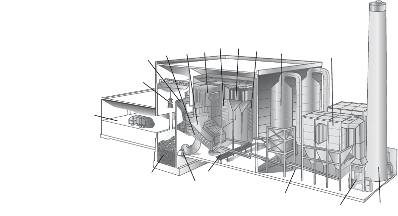
While nonhazardous wastes can be incinerated in a wide variety of different types of furnaces, the vast
majority of municipal refuse and nonhazardous commercial and industrial wastes are incinerated in
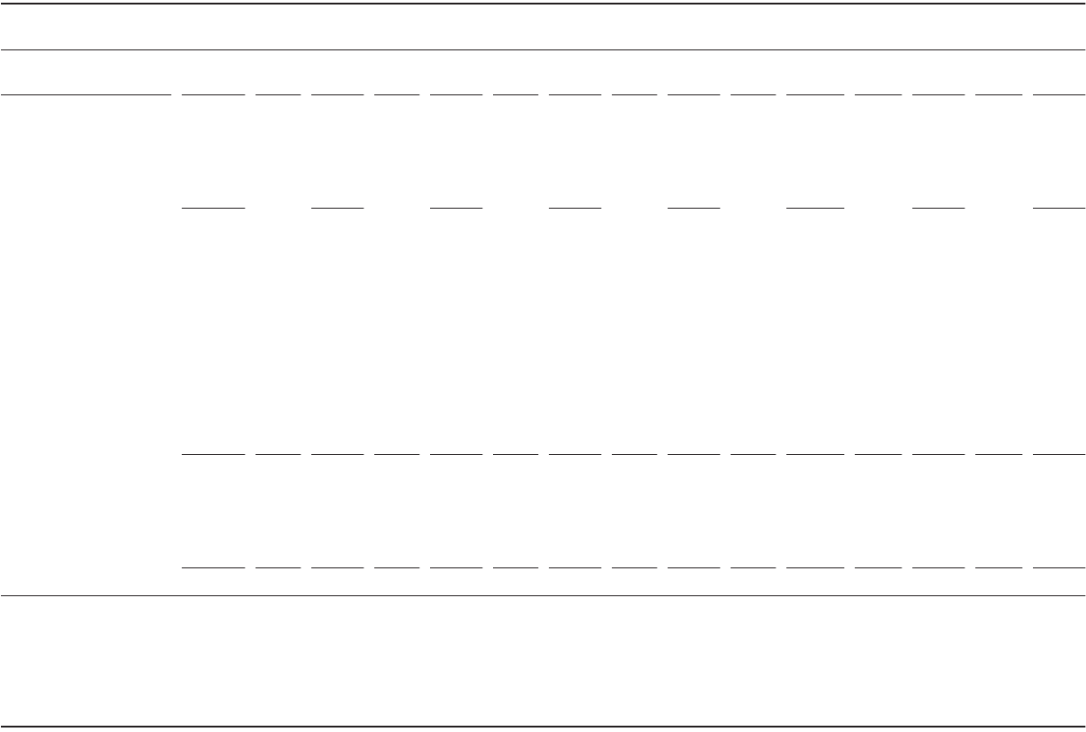
mass-burn waste-to-energy plants similar to the one shown in Fig. 13.2. The term mass burn refers to
the fact that the waste is not pretreated prior to being fed to the incinerator, although large objects such
as large appliances (white goods) or construction debris (most especially gypsum board) will usually be
removed.
Incinerator systems incorporate the following components: (1) waste receiving, (2) waste storage and
segregation, (3) waste burning, (4) ash discharge, (5) heat recovery, (6) acid gas control, (7) particulate
control, and (8) fan and stack.
184 1872 1772 1 94.. MMBtu hr MMBtu hr¥
()
=
© 2003 by CRC Press LLC
13-36 The Civil Engineering Handbook, Second Edition
Wastes are received on the tipping floor, where vehicles arrive and dump their loads of refuse into the
holding pit. During this process, an operator will typically identify objects and materials that are unsuit-
able for incineration, such as large objects, major appliances (white goods), or noncombustible construc-
tion debris, most especially gypsum board and other gypsum products. The waste feed-crane operator
typically segregates these wastes from the waste that will be incinerated. Large objects can result in
jamming of the waste feed and transport mechanism and, if they are combustible, they will, if possible
be broken up prior to incineration.
White goods, typically appliances and fixtures, have very few combustible components and are typically
segregated in the receiving area. Refrigerators and air conditioners are a particular concern because they
may contain chlorofluorocarbons (CFCs), which can produce highly corrosive hydrogen fluoride during
combustion. CFC incineration is also not legal in most nonhazardous waste incinerators. Gypsum is kept
out of the combustion chamber, because it will release sulfur dioxide (S~) in excess of the environmentally
acceptable limits for the combustor when heated to combustion temperatures.
The waste from the refuse holding pit is fed by a crane into a chute leading to a grate. The grate may
be a moving screen, a set of reciprocating, or fixed grates. The important factor is to move the burning
mass through the combustion chamber and to discharge the ash into a suitable receiver. The grate must
allow a sufficient solids residence time for the combustibles in the waste to burn down completely. Typical
solids residence times range from 30 min to several hours for municipal refuse. Shorter solids residence
times occur for highly flammable, light, materials, longer residence times for heavy materials such as
flammable furniture. Waste consisting of paper and other light materials could have an even shorter
solids residence time. The ash remaining after incineration passes fall into a collection and discharge
system. The ash may drop into a water-filled tank or trough, where it is cooled and then the slurry
discharged or moved onto a dry conveyor where it is air cooled prior to discharge. The steam and hot
gases from either type of ash handling system are typically drawn back into the furnace.
The combustion chamber can be refractory lined or it may (as shown in Fig. 13.2) be lined with steam
tubes similar to those in a boiler. Steam-tube lined combustion chambers are often termed “water-wall
furnaces.” The gases then pass through a series of heat exchangers similar in concept to the heat recovery
parts of any steam boiler. The gases are thus cooled, and energy is converted to useful steam. Some
incinerator designs will include a quench, where (not shown) the gases are further cooled with water
sprays. The cooled gases enter the air pollution control system.
FIGURE 13.2 Waste to energy facility. (Reproduced courtesy of COVANTA Energy.)
3
4
5
8
9
10
11
12
13
14
17
16
15
7
6
2
1
1. Tipping floor
2. Refuse holding pit
3. Grapple feed chute
4. Feed chute
5. Martin stoker grate
6. Combustion air fan
7. Martin ash discharger
8. Combustion chamber
9. Radiant zone (furnace)
10. Convection zone
11. Superheater
12. Economizer
13. Dry gas scrubber
14. Baghouse
15. Fly ash handling system
16. Induced draft air fan
17. Stack
© 2003 by CRC Press LLC