Woodyard D. (ed.) Pounders Marine diesel engines and Gas Turbines
Подождите немного. Документ загружается.

Design refinements included the introduction of a revised configuration of
compact pulse converter exhaust system in stainless steel, with a larger bore
and optimized area ratios, fostering a better gas flow that improves fuel effi-
ciency. The system became standard on new engines and has been retrofitted
to existing V16- and V20-cylinder installations. Engine tests confirmed the
performance simulation prediction that the larger flow area, if applied alone,
would in fact reduce turbine energy in the turbocharger and actually increase
exhaust temperature without any significant improvement in fuel economy.
A turbocharger rematch, however, resulted in an overall reduction in turbine
inlet temperature by up to 30°C and a reduction in specific fuel consumption
of around 3 per cent.
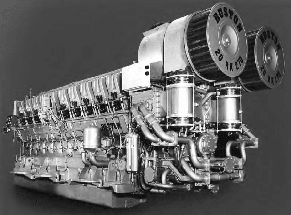
New 20RK270 engines also benefited from two TPL 65 turbochargers, the
latest generation from ABB Turbo Systems (see Chapter 7). The higher effi-
ciency of these units, compared with the previous VTC 304 type, yielded a
further reduction in exhaust temperature and specific fuel consumption at full
power. When applying such high-efficiency turbochargers to engines operat-
ing over a propeller law power curve, it is desirable to introduce an air bypass
between the air manifold and the turbine inlet manifold over the lower part of
the speed range. Such an arrangement delivers a further significant reduction in
turbine inlet temperature in the region around 30 per cent power at 700 rev/min,
and also improves the stability of the turbocharger compressor. The bypass
valve is an integral part of the engine, programmed by the Regulateur Europa
Viking 22 governor to open and close at pre-selected engine speeds: typically
opening on a rising engine speed at 580 rev/min and closing at 920 rev/min.
Ruston (MAN Diesel) 629
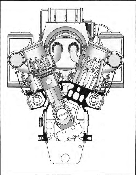
FiguRe 24.3 V20-cylinder version of RK270 engine
630 Ruston (MAN Diesel)
Two main modifications were made to ensure compliance with IMO’s
Marpol Annex VI NOx emission requirements:
l The fuel injection timing was retarded by approximately 5°, this change
alone resulting in a NOx emissions reduction of some 20 per cent when
calculated in accordance with the E3 test cycle appropriate to a propeller
law-operated engine. Unfortunately, the specific fuel consumption was
adversely affected.
l The compression ratio was increased from 12.3 to 13.3 by a simple
adjustment that had been incorporated in the engine design; this
allowed advantage to be taken of the increase in maximum cylinder
pressure resulting from the fuel injection retardation. The change
caused a rise in NOx emission but of less than 3 per cent, and the
resulting emissions were compliant with the IMO requirements; further-
more, most of the fuel consumption ‘lost’ by the injection retardation
was restored. The increased compression ratio also improved starting
on poorer quality fuels and curbed particulate and smoke emissions,
particularly at part load.
Ruston gained valuable experience with selective catalytic reduction (SCR)
installations required to satisfy extremely low NOx emission limits dictated
in special regions. The four 20RK270 engines powering the 110 m long fast
monohull ferry Gotland exhaust via Siemens SINOx systems which reduce
emissions to below 2 g/kW h—less than 20 per cent of the IMO standard.
RK270 eNgiNe DeTAils
The bedplate is machined from a high-grade iron casting. Transverse dia-
phragms for each main bearing provide rigid support for the crankshaft, and
angled joint faces ensure positive locking of the main bearing caps in the bed-
plate. The crankshaft is machined from a single-piece alloy steel forging with
bolted-on balance weights. There is an integral forged coupling flange for the
flywheel, and the camshaft drive gear is split to facilitate replacement.
The main bearings are pre-finished, steel-backed shells with bimetal lin-
ings and are retained in the housing by caps drilled to direct oil to the bearings.
The caps are located transversely in large registers in the bedplate and held
in position by studs and nuts. The bearings are easily removable through the
crankcase doors.
The crankcase housing has transverse diaphragms between each cylinder
to provide water compartments around the cylinder liners. It incorporates an
integral air chest and is machined from a high-grade ductile spheroidal graph-
ite iron casting. Explosion relief valves are fitted to the crankcase doors which
allow easy access to the connecting rods and main bearings and to the cam-
shaft and drive.
Separate wet-type liners cast in alloy iron are flanged at their upper ends
and secured by the cylinder heads. Cutting rings are fitted at the top of the liner
to prevent the build-up of carbon on the piston crowns. The lower ends of the
liners are located in the crankcase and sealed by synthetic rubber rings. The
liners are machined all over and the bore is hone finished to secure good pis-
ton/liner compatibility.
A single camshaft for each cylinder bank is installed from the side of the
engine and run in generously proportioned bearings. The camshafts are of
modular construction with single-cylinder sections joined by bearing journals.
Individual sections can be replaced with the camshaft in situ or the complete
camshaft removed from the side. The final timing is adjustable through a slot-
ted driven gear and hub assembly. The camshafts are driven by a train of hard-
ened and ground steel spur gears from the crankshaft split gear.
A two-piece piston, comprising a steel crown and an aluminium skirt, fea-
tures a combustion bowl of the Hesselman design. Cooling oil is fed from the
connecting rod through the small end bush and drillings in the gudgeon pin
and piston body to the cooling gallery. The connecting rods are manufactured
from steel forgings. The shell bearings are carried in obliquely split big ends,
with the cap located by serrations on the joint face (a feature reducing the
bending and shear loads across the joint). The stepped small end has a large
diameter gudgeon pin with bronze bushings. A drilling through the shank of
the connecting rod delivers oil for small end bearing lubrication and piston
cooling.
Individual cylinder heads are machined from iron castings which accom-
modate two inlet and two exhaust valves surrounding a central fuel injector.
Both the air inlet port and the exhaust port are located on the same side of
the cylinder head. The inlet port draws air from the integral air chest, and the
exhaust port feeds into a manifold system mounted above the air chest. Each
pair of valves is operated via short stiff pushrods and conventional rockers. The
pushrods are driven from the side entry camshafts via roller cam followers.
The fuel injection system features individual pumps directly operated from
the camshaft, and injectors for each cylinder.
Air motor starting is standard, using one or two motors operating via spur
gears on the flywheel rim.
A sensitive hydraulic governor is bevel driven from the camshaft. Over-
speeding is prevented by a separate safety trip mechanism which returns the
control shaft to the ‘No-Fuel’ position. A digital electronic governor is available
as an option.
Auxiliaries are driven from the free end of the engine through a spring
drive and spur gears. The standard arrangement embraces one water pump for
the jacket water, one water pump for the charge air coolers and lubricating oil
cooler circuits, a fuel lift pump and lubricating oil pumps. A secondary water
pump may be fitted optionally. An extension shaft may be fitted to allow power
to be taken from the free end of the engine.
The lubricating oil system includes single or twin engine-driven pumps,
full flow filtration, thermostat and oil cooler. The oil pressure is controlled by a
single or double spring-loaded relief valve. The jacket cooling system is ther-
mostatically controlled and includes an engine-driven water pump.
RK270 engine details 631
632 Ruston (MAN Diesel)
The turbocharger(s) is mounted as standard at the free end of the engine,
although a flywheel end location can be arranged if required.
RK215 eNgiNe
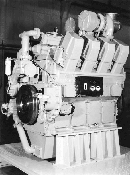
The 215 mm bore/275 mm stroke RK215 engine (Figure 24.4) was originally
produced in in-line six and V8 versions but V12 and V16-cylinder models
later extended the upper power limit to 3160 kW at 720–1000 rev/min. RK215
engines have earned references in commercial and naval propulsion and genset
applications, Ruston summarizing the benefits of the design to operators as:
cost-effective; high power-to-weight ratio; reduced space requirements; ease of
installation; fuel efficient; and minimized environmental impact.
The general layout of the engine is conventional with wet cast iron liners
and an underslung crankshaft. The latter feature was a departure for Ruston
which had formerly produced bedplate-type engines (see RK270 model in this
chapter). The change in design philosophy reflected the high cylinder pres-
sures (up to 180 bar), dictating a level of crankcase strength that could only be
obtained from an underslung configuration.
FiguRe 24.4 Ruston RK215 engine in V8-cylinder form
The combustion space is sealed by a steel ring, and each cylinder is held
down by six bolts. The underslung crankshaft is mounted to the block with rigid
bearing caps, each having two studs; in addition, the V-cylinder engine uses
cross-bolts for cap location. Hydraulic tensioning is applied to secure the ver-
tical studs. The alloy steel crankshaft is a die forging with bolted-on balance
weights, two for each throw, to maximize bearing oil film thicknesses. The
bearing shells are of bimetal construction with an aluminium–tin–silicon run-
ning surface which has a very high strength. In spite of the high cylinder pres-
sures, the designer claimed, the bearings are not highly loaded: the large end
being under 41 MPa.
A two-piece die forging forms the connecting rod, with the large end split
at 50° to the vertical to allow removal through the cylinder bore. The split
angle was optimized through model tests and finite element analysis to provide
minimum bending at the split position under both firing and inertia load condi-
tions, while maintaining an adequate bearing diameter and large end bearing
housing rigidity. Each cap is retained by four bolts. The small ends of the con-
necting rods are stepped to minimize pressures on both small end bearing and
piston boss.
The pistons are one-piece nodular iron castings with an integral cooling
gallery fed with oil through drillings in the connecting rod and gudgeon pin.
A three-ring pack is specified for the piston, all the rings having chrome run-
ning faces; the top ring is asymmetrically barrelled and the second ring is taper
faced. The grooves for the compression rings have hardened surfaces. The oil
control ring is one piece with a spring expander. Six drilled holes in the piston
drain excess oil from the oil control ring back inside the piston.
Oil, water and fuel lift pumps are all driven by hardened steel gears located
at the non-flywheel end of the crankshaft. The rotor-type oil pump delivers up
to 400 l/min for lubrication and cooling via an engine-mounted cooling and
filtration system which incorporates a change-over valve to enable continuous
operation. The standard freshwater pump may be supplemented by one or, in
special cases, two additional pumps to supply heat exchangers. The standard
cooling system incorporates a freshwater thermostat and water bypass. Also
standard is the fuel lift pump and pipework incorporating a pre-filter, fine fil-
ter and pressure regulating valve. The pump is sized to give a 3:1 excess feed
capacity to provide cooling for the injection pumps.
Unit injectors for each cylinder were specified (reportedly for the first
time in British medium-speed engine practice), operating at pressures up to
1400 bar. The injectors, purpose-developed for the RK215 by L’Orange in con-
junction with Ruston, are operated from the camshaft via a pushrod. A charac-
teristic feature cited for unit injector engines is a low level of exhaust smoke
in all operating conditions. Fuel is supplied to the injectors through drillings
in the cylinder head, dispensing with high-pressure fuel lines and removing a
potential cause of engineroom fire.
The iron cylinder heads are of two-deck construction with a very thick bot-
tom deck which is cooled by drilled passages. Inlet and exhaust valve pairs are
RK215 engine 633
634 Ruston (MAN Diesel)
generously proportioned at 78 mm and 72 mm diameter respectively, and also
feature wide seats to foster low seating pressures and good heat transfer from
the valves to the seat inserts. This is particularly important because the exhaust
seat insert incorporates a water-cooled cavity to maximize heat flow from the
valves. The cooled exhaust seat is made from steel with a hardened surface,
while the inlet valve uses the more common high chromium content iron.
Both inlet and exhaust ports are located on the same face of the cylinder
head. The valves, which have hardened seat faces, are operated by rocker levers
and bridge pieces. A third rocker lever between the valve rockers operates the
unit fuel injector. All rocker levers on each line are actuated by pushrods and
lever-type followers from the induction-hardened alloy steel camshaft. All
bearings, including those for the follower roller and the spherical pushrod ends,
are positively lubricated from the main oil supply at full pressure.
Two Garrett TV94 turbochargers were specified for the six-cylinder in-
line model, each mounted on a very short manifold served by three cylinders.
Charge air is fed from both units via a manifold to a single, integrally mounted
air/water charge cooler. This arrangement is facilitated by the positioning of
the inlet and exhaust on the same side of the engine. The resulting small vol-
umes of both inlet and exhaust systems, plus the low turbine and compressor
inertia, reportedly promote excellent load acceptance. A similar concept is
applied to the V8-cylinder model but with the Garrett turbochargers replaced
by dual ABB RR151 units.
V-cylinder models use similar line components to the in-line cylinder mod-
els: the cylinder head, piston, liner and connecting rod are the same, as are the
cam followers, pushrods and camshaft drive. The crankcase and crankshaft, of
course, are different.
To ensure that the underslung main bearing cap is rigidly located it is pro-
vided with cross-bolts in addition to the hydraulically tensioned main studs.
V-engines use side-by-side connecting rods, and the crankshaft—while hav-
ing the same size of crankpin as the in-line engine—has a 25 per cent larger
main bearing journal diameter. The resulting overlap between pin and journal
imparts strength and rigidity to the crankshaft.
RusTON RK280 eNgiNe
An advanced 280 mm bore RK280 medium-speed design developed by Ruston
for fast commercial and naval vessel propulsion, introduced in 2001, was
taken under the MAN Diesel umbrella and is now produced in Germany as the
28/33D series (see Chapter 22 for details).
635
C h a p t e r | t w e n t y f i v e
SEMT Pielstick (MAN
Diesel group)
SEMT Pielstick of France can claim a pioneering role in developing and promot-
ing medium-speed engines for propulsion through in-house production and licen-
sees in key shipbuilding countries, notably Japan. The PC medium-speed design
interests of Paris-based SEMT (Société des Études de Machines Thermiques) are
now wholly under the umbrella of Germany’s MAN Diesel group.
The histories of MAN and SEMT Pielstick are closely linked. The latter’s
German founder, Gustav Pielstick, began working for MAN in 1911 and stayed
with the company for almost 35 years. After World War II he became technical
manager of SEMT, which had been created by the French government in 1946
with the involvement of five companies. An initial project was to adapt the
MAN 40/46 submarine engine for commercial markets. SEMT subsequently
pursued development of high-speed PA and medium-speed PC diesel engines.
From 1988, SEMT was jointly run by MTU Friedrichshafen and MAN
Diesel, first as a 50:50 joint venture and then, from early 1998, under an
arrangement in which MAN held two-thirds and MTU one-third of the shares.
In October 2006, MAN Diesel SE of Augsburg acquired full control of SEMT
Pielstick which subsequently became a brand in the German parent’s portfolio.
Numerous examples remain in service at sea but PA and PC engines are
no longer produced in France for marine applications (although some models
are still manufactured for nuclear power station back-up and submarine pro-
pulsion). The main focus of production at St-Nazaire is now on MAN Diesel’s
successful 48/60 series medium-speed engines, whose latest derivative features
common rail fuel injection (see Chapter 22).
The Pielstick marque originated in the early 1950s as part of a family of
monobloc multiple-crankshaft engines designated the PC1 series. The first PC1
engine ran in 1951 and initial tests with heavy fuel oil (380 cSt) followed in
1953. The first commercial installation, a power station engine, was commis-
sioned in 1953 and the first PC marine engine ran on heavy fuel in 1959.
Further development resulted in more conventional single-crankshaft
designs: the 400 mm bore PC2 series, introduced in the mid-1960s; the 480 mm
bore PC3 series, introduced from 1971; and the 570 mm bore PC4 series which
636 SEMT Pielstick (MAN Diesel Group)
was launched in the late 1970s. The PC3 series was phased out but successive
modernization and upgrading programmes for the PC2 and PC4 designs
resulted in the PC2-6B and PC4-2B versions, which provided the main SEMT
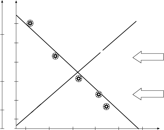
Pielstick thrust in the latter years. The rise in maximum firing pressure and
reduction in specific fuel consumption for successive generations of 400 mm
bore PC2 designs are illustrated (Figure 25.1).
Experience gained with the PC2-2 design showed that the one-piece light
alloy piston had to be abandoned in favour of the first two-piece design with
steel crown and forged light alloy skirt. Developed by SEMT Pielstick in con-
junction with a leading piston manufacturer, the new concept allowed higher
mechanical and thermal loads, and secured better production quality. The PC2-5
engine, launched in 1973, benefited from this development in delivering a
30 per cent increase in power over the original PC2-2. Other refinements
included a bore-cooled cylinder liner and a bevel-cut connecting rod allowing
the crankpin diameter to be enlarged.
New turbocharging and fuel-optimized injection systems were applied to
the PC2-6 engine, launched in 1982. The modular pulse converter (MPC) tur-
bocharging system features an almost constant pressure exhaust gas feeding to
each turbine through a single exhaust pipe.
Longer stroke derivatives arrived in the mid-1980s to supplement the
PC2 and PC4 series, these PC20 and PC40 models retaining the 400 mm
and 570 mm bore sizes but exploiting higher stroke–bore ratios, respectively,
increased from 1.15 to 1.375:1 and from 1.08 to 1.31:1. Significantly lower
P
max
(bar)
Cs
(g/kW h)
PC2
PC2-6
PC1
P
max
Cs
PC2-5
230
220
210
200
190
180
150
100
70
50
1950 1960 1970 1980 1990 2000 Year
PC20
FiGurE 25.1 Development of fuel consumption (Cs) and maximum ring pressure
(P
max
) ratings for successive SEMT Pielstick 400 mm bore PC engine designs
specific fuel consumptions were achieved. The PC20, with a stroke of 550 mm
and rating of 607 kW/cylinder at 475 rev/min, was subsequently dropped from
the programme.
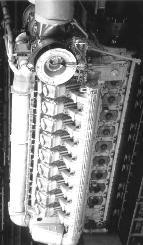
In 1996 SEMT Pielstick’s Japanese licensee Diesel United delivered the
world’s most powerful medium-speed engines which were specified for pro-
pelling long haul coastal ferries. Each V18-cylinder PC4-2B model in the
twin-engine installations yielded a maximum continuous output of 23 850 kW
at 410 rev/min (Figure 25.2).
SEMT Pielstick (MAN Diesel group) 637
FiGurE 25.2 SEMT Pielstick 18PC4-2B propulsion engine (23 850 kW at 410 rev/min)
on resilient mountings
638 SEMT Pielstick (MAN Diesel Group)
PC2-6B DESiGN
The last manifestation of SEMT Pielstick’s 400 mm bore PC2 medium-speed
engine, the 500 mm stroke PC2-6B design, developed 615 kW/cylinder at 500–
520 rev/min. An output range up to 11 340 kW was covered by six, seven, eight
and nine in-line and V45° 10-, 12-, 14-, 16- and 18-cylinder models (Figures
25.3 and 25.4); a V20-cylinder version was also planned. The PC2-6B engine
retained the same overall envelope for propulsion installations as the shorter
stroke (460 mm) PC2-6 predecessor as well as its overhaul space requirements.
Planning the PC2-6B engine, the designers aimed to increase power out-
put by at least 10 per cent over the established PC2-6 model without penal-
izing specific fuel consumption and making maximum use of experience from
the PC20 (400 mm bore/550 mm stroke) series which was introduced in 1985
(Figure 25.5). A rise in power through a higher mean effective pressure rating
was limited by:
l The pressure ratio of contemporary turbochargers.
l A peak combustion pressure deliberately limited to 150 bar and a com-
pression ratio set at 12.5 to allow trouble-free burning of heavy fuels.
FiGurE 25.3 Cross-section of PC2-6B engine