Woodyard D. (ed.) Pounders Marine diesel engines and Gas Turbines
Подождите немного. Документ загружается.

650 Sulzer (Wärtsilä)
two-stroke design was succeeded in 1972 by a four-stroke version (the Z40) which
was in turn completely redesigned and replaced in 1982 by the ZA40 engine. A
longer stroke (560 mm instead of 480 mm) ZA40S engine was introduced in 1986
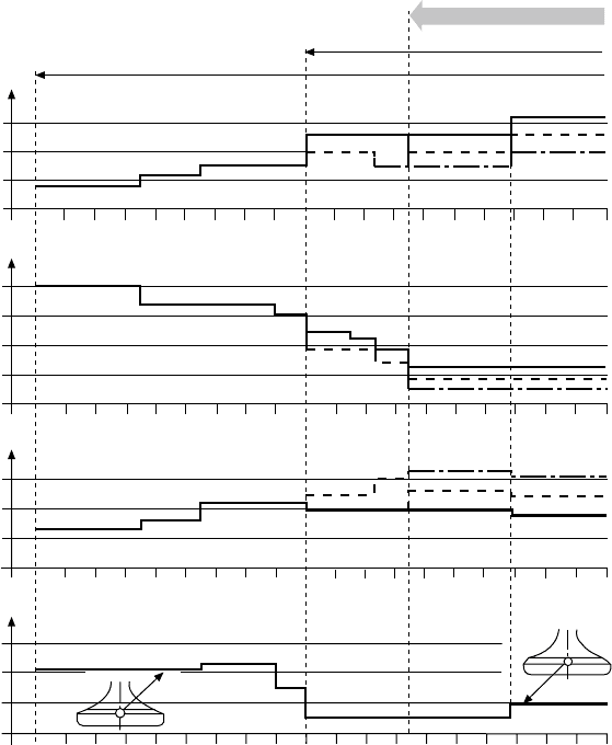
to succeed the Z40 and ZA40 designs. The performance development steps over
the years are illustrated in Figure 26.2.
In autumn 1988, 3 years after its announcement with a cylinder output of
660 kW, the ZA40S was uprated to 720 kW/cylinder following successful serv-
ice experience and heavy fuel endurance tests. The new rating was associated
with an increased maximum cylinder pressure of 165 bar and mean effective
pressure of 24.1 bar, underwritten by thermodynamic and mechanical optimi-
zations. Some design modifications were also introduced to improve product
reliability and durability in general (Figure 26.3):
MCR
B.S.F.C
ratio: p
max
/b.m.e.p
kW
°C
1972 73 74 75 76 77 78 79 80 81 82 83 84 85 86 87 88 89 90 91
Year
ER II
ER I
MCR
MCR
ER I
ER II
MCR
ER I
ER II
Cylinder output
Valve seat temperature at MCR
700
600
500
400
210
g/kW h
200
190
180
170
8
7
6
500
450
400
350
ZA 40
Z 40
ZA 40S
FIgure 26.2 development steps of successive Sulzer Z40, ZA40 and ZA40S designs
illustrated by key performance parameters
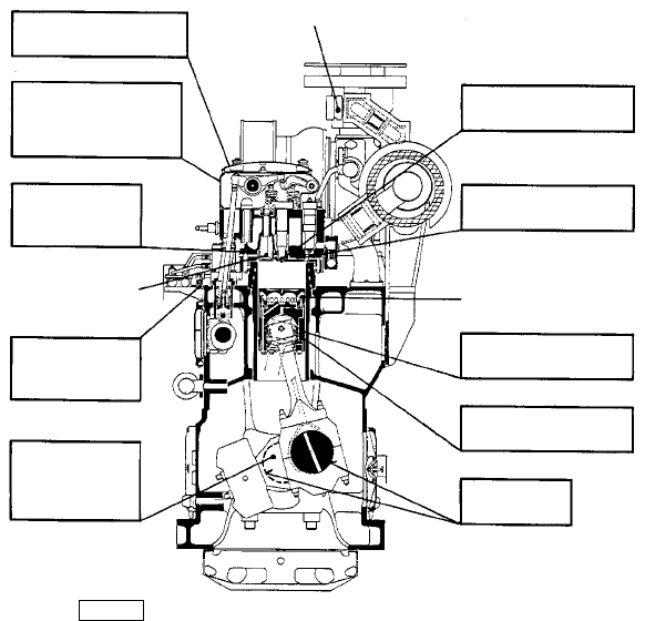
l An exhaust valve with a 45° seat angle, this refinement achieving: better
cooling without reduction of mechanical and thermal safety at the higher
engine load and maximum cylinder pressure; and more efficient seating
due to a wider seat area.
l Sulzer’s new combined ‘jet-shaker’ piston cooling principle in which the
conventional shaker effect in the piston crown is supplemented by oil
jets sprayed through nozzles. This offers advantages in lowering piston
crown temperatures, thereby preventing carbon formation and gaining
an improved washing effect.
l A new version of the waste gate in the exhaust gas manifold before the
turbine, securing a better match between the engine and turbocharger at
the increased power rating.
rotating Piston
A classic feature of Sulzer Z-type engines retained throughout successive gen-
erations is the rotating piston. Sulzer patented the concept in 1937 after tests
on a number of research engines with cylinder bores from 90 mm to 420 mm
which confirmed the special benefits offered for highly loaded trunk piston
Introduction 651
Introduced for all engine power steps (600–720 kW/cyl)
Jet-shaker cooled
piston
Corrosion-free
injection nozzle
Exhaust
waste gate
Aluminium
bearings
Chromium-plated oil
scraper ring
Improved piston
skirt shape
Wear-resistant inlet
valves
Continuous grain
flow forged
crankshaft
Reinforced
regulating
linkage
45° Nimonic
exhaust valve
Improved relief
valve
Electronic speed-
governor
Reinforced governor
drive and overspeed
cut-off device
FIgure 26.3 Main modications for uprated ZA40S engines
652 Sulzer (Wärtsilä)
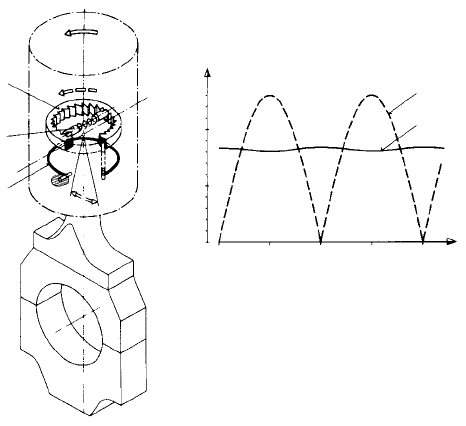
engines. A ratchet mechanism transforms the swinging motion of the connect-
ing rod into a smooth rotation of the piston (Figure 26.4). The connecting rod
has a spherical small end which allows some 40 per cent more bearing area
than a gudgeon pin bearing.
The rotating piston was eventually adopted for the Z-type design, first intro-
duced in two-stroke form in 1964. The concept remained unique to Z-engines
until its adoption in 1995 for GMT’s upgraded 550 mm bore VA55 medium-
speed model. (The Italian designer benefited from a technology transfer arrange-
ment with Sulzer; both later became members of the Wärtsilä Corporation.) For
rotating the piston, the connecting rod is provided with two pawls positioned
slightly out of the centre of the spherical small end bearing. When the connect-
ing rod performs its swinging movement relative to the piston, the pawls impart
an intermittent rotating motion to a toothed rim, from which it is transmitted to
the piston by an annular spring. The flexible connection maintains the forces
necessary for rotating the piston at a constant low level.
Sulzer cites the following merits of the rotating piston:
l Even distribution of temperature around the piston crown, as there are
no particular inlet and outlet zones.
l Small and symmetrical deformation from a top end bearing with a rela-
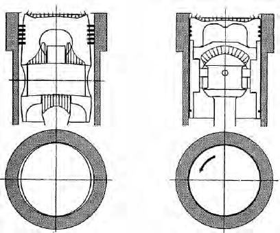
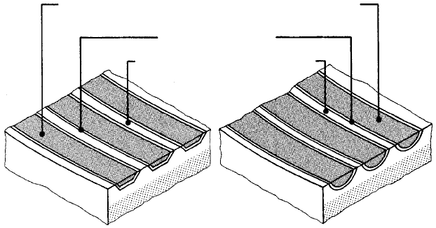
tively large area and of spherical design (Figure 26.5).
l Optimum sealing and working conditions for the piston rings because
the small, symmetrical deformations of the piston allow the use of the
smallest running clearance between piston and cylinder liner.
n = 530 rpm
0° 90° 180° 270° 360°
ω
rad/s
1.0
0.5
0
Spring
Ratchet-ring
Ratchet
ω
P
ω
R
ω
P
ω
R
= angular velocity of the piston
= angular velocity of the ratchet-ring
ω
P
ω
R
FIgure 26.4 drive principle of rotating piston
l Low and stable lubricating oil consumption because the small piston
running clearances minimize piston slap and obviate the need for the tra-
ditional oil cushion, thereby allowing the oil scraper ring to be located at
the lower end of the piston skirt.
l Good margin for unfavourable running conditions with the smallest risk
of seizure because the grey-iron piston skirt is always turning to a fresh
part of the cylinder liner surface.
ZA40 And ZA40S engIneS
The last ZA40S programme was released with a rating of 750 kW/cylinder at
510 rev/min on a mean effective pressure of 25.1 bar and with a mean piston
speed of 9.5 m/s. Six, eight and nine in-line models and V12-, 14-, 16- and
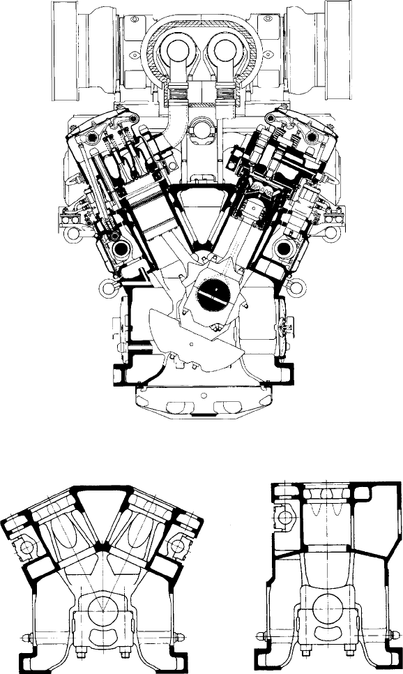
18-cylinder models covered a power band from 4500 kW to 13 500 kW (Figure
26.6). The crankcase is fabricated for in-line cylinder engines while V-form
versions feature a cast iron monobloc. The originally fabricated two-part design
of the Z-engine frame was superseded by a monobloc casting for the ZA40
and ZA40S in-line models, as had always been standard for the V-engines
(Figure 26.7).
Uneven cylinder liner wear was initially encountered in the mid-1970s by
the first Z40 engines burning blended or heavy fuel oils with increased sul-
phur content, at a height equal to the top dead centre of the piston rings. This
wear could be defined as local low-temperature corrosion which was coun-
tered by a four-step solution: (1) ensuring adequate alkalinity of the lubricat-
ing oil, (2) modified cylinder lubrication, (3) higher cooling water temperature
and (4) increased cylinder liner wall temperature from a modified bore-cooling
ZA40 and ZA40S engines 653
FIgure 26.5 Symmetric design, with rotation, ensures that Sulzer Z-engine pistons
(right) keep their circular form. gas and mass forces are transmitted centrally through
the spherical bearing with no load on the piston skirt. Comparison is with a conven-
tional gudgeon pin arrangement (left)
654 Sulzer (Wärtsilä)
arrangement with local insulating tubes. (Operators of earlier Z40 engines were
offered insulating tube sets, together with appropriate fitting devices, for ret-
rofit to original cylinder liners during a routine overhaul.) Subsequent service
results demonstrated that these measures reduced low-temperature corrosion to
a negligible (if any) amount.
FIgure 26.6 Sulzer ZA40S engine showing the rotating piston, fully bore-cooled
combustion space and single-pipe exhaust system
FIgure 26.7 engine blocks of ZA40S vee-form and in-line cylinder versions
A modified O-ring material (changed to a silicon quality and an appropriate
fluor elastomer quality, such as Viton) was adopted for the cooling water space
of the cylinder liner after leakage was experienced with some units. The dry
lower half of the liner almost entirely eliminates the risk of water leakage into
the crankcase and contamination of the lubricating oil.
The double-bottomed water-cooled cylinder heads of Z40 engines, made
of cast iron, performed well. Some cracks resulted, however, either from cast-
ing and machining faults or from the supply of spares not intended for engines
with the later, higher outputs. The material for the O-rings of the valve seats
and guides was also changed to an appropriate fluor elastomer quality, both
with good results.
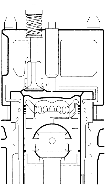
The cylinder heads of the ZA40 and ZA40S engines are bore cooled
(Figure 26.8). The measured bottom deformations under gas load are only
one-third those of the conventional double-bottom head, and the mechanical
ZA40 and ZA40S engines 655
FIgure 26.8 Fully bore-cooled combustion space of Sulzer ZA40S engine
656 Sulzer (Wärtsilä)
stresses were also found to be low in the same proportion. The drilled cooling
passages permitted a uniform temperature adjustment within a few degrees at
the desired low level. The resulting low thermal distortion as well as the high
mechanical stiffness fosters good valve seat sealing with optimum heat transfer
to the exhaust valve seats.
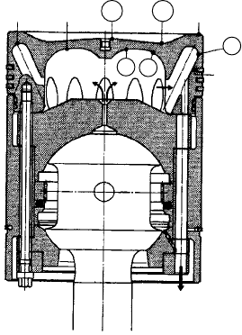
The well-proven rotating piston concept was retained for the ZA40 and
ZA40S engines but benefited from simplification; bore cooling of the crown
was also introduced. An optimized arrangement of the cooling bores reduced
stresses by around 10 per cent with practically no change in crown temper-
atures. The substantially stiffened periphery secured by bore cooling also
resulted in reduced thermal deformation of the crown and hence improved
working conditions for both piston and rings (Figure 26.9).
The top ring of the ZA40S piston features a Sulzer plasma-coated running
face, while the running faces of the other two rings are chromium plated. All
three rings are barrel shaped to promote initial running in and to avoid a need
to hone smoothened cylinder liners at routine overhauls. (The complete set
of piston rings and scraper rings should therefore be replaced during a piston
overhaul.) The flanks of the rings and their grooves are also chromium plated.
Sulzer reports that a combination of bore-cooled rotating pistons and plasma-
coated piston rings promotes low wear rates and long piston life. Rotation and
negligible distortion due to the spherical top end, as well as no transmission of
gas forces through the cast iron piston skirt, underwrite a small skirt clearance.
The connecting rod with marine-type bottom end features large crankpin
diameters and hydraulically tightened studs for easy maintenance; no interfer-
ence with the bottom end bearing is necessary at piston overhauls. Shims can
be applied to achieve the different compression ratios for three engine tuning
options.
209°C 220°C
b
a
310°C
136°C
e
c
d
FIgure 26.9 Measured temperatures in a ZA40S engine’s rotating piston
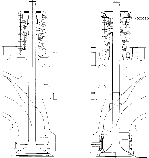
The well-proven exhaust valve arrangement refined over many years in the
Z40 and ZA40 engines was retained for the ZA40S: Nimonic exhaust valves with
rotators and water-cooled valve seat inserts but no valve cages (Figure 26.10). The
higher rigidity of the bore-cooled cylinder head and the generally lower tempera-
ture levels from the enhanced turbocharging system further improved the sealing
conditions of the exhaust valves in the ZA40S. Longer times-between-overhauls
were thus secured, the intervals coinciding with those for the piston.
A new generation of aluminium/tin alloy bimetal-type bearings was intro-
duced for both main and bottom end bearings of ZA40 and ZA40S engines
(Figure 26.11). These ‘Rillenlager’ and bimetal types dispensed with the tra-
ditional overlay of the previous tri-metal type to give the following reported
benefits: sustained fatigue resistance and embeddability; better wear resistance
for heavy fuel operation; improved local self-healing and emergency running
behaviour; and better adaptability after inspections.
The loading of the spherical top end bearing remained some 15–20 per cent
lower than that of a conventional gudgeon pin design. The big end of the ZA40
and ZA40S connecting rod was also enlarged from the Z40 design, resulting
ZA40 and ZA40S engines 657
FIgure 26.10 Inlet valve (left) and exhaust valve (right) of ZA40S engine
658 Sulzer (Wärtsilä)
in a reduction of the dynamic stresses of around 20 per cent. The bolts are
hydraulically tightened for easier and faster maintenance procedures.
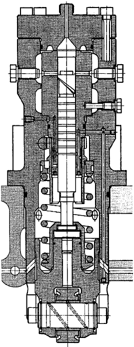
Helix-controlled fuel injection pumps (Figure 26.12) are provided for each
cylinder, with fuel leakage into the lubricating oil prevented by an oil barrier at
the lower end of the plunger sleeve. Depending on the engine application, helix
control edges can be chosen for constant or variable injection timing (CIT or
VIT). The simple arrangement of short high-pressure fuel pipes to the injection
valves, together with the circulation of preheated fuel oil up to the level of the
pumps, underwrites routine pier-to-pier operation on heavy fuel (with appro-
priate circulation and preheating).
The injection valves (Figure 26.13) are equipped with sleeve-type noz-
zles cooled by freshwater and provided with rounded-off inner edges of the
spray holes (Figure 26.14). Rounded-off spray holes are traditional for Sulzer
nozzles and reportedly result in a more stable spray pattern over longer service
periods with a narrower scatter of injection rates between individual cylinders.
A more corrosion-resistant sleeve material was introduced to replace the origi-
nal material whose punishment threshold was not large enough to cope with
corrosion attacks by insufficiently treated cooling water (as a result, some tip
breakages occurred).
Plunger seizures initially occurred on Z40 engines due to insufficient clear-
ance (either through manufacturing with too small a clearance or reduction of
clearance in heavy fuel service as a result of the tendency of the material used
earlier to grow at higher temperature levels). An increased plunger clearance
and a changeover to a new material specification for the plungers, supported
by stricter quality control, proved to be design remedies. Operationally, ship-
yards and operators must take care that no undue impurities are present in the
Barrier layer : Ni
Shell back: Steel
Running layer 2: Al with 6% Sn
Running layer 1: Pb Cu Sn-(or Sn Sb-) overlay as groove
fillings
FIgure 26.11 Features of ‘rillenlager’-type bearings: thickness of the Al/Sn running
layer no. 2 is a few tenths of a millimetre; depth of grooves is a few hundredths of a
millimetre; grooves are laid as a helical thread; shape and dimension of grooves may
vary, depending on the manufacturer
fuel and lubricating oil systems which may lead to avoidable plunger seizures.
Slow heating up of the fuel system and the maintenance of the correct tempera-
ture level for the heavy fuel oil used are also advisable.
Some sticking of fuel pump plungers was reported from a growing lac-
quer formation on the guide part side, depending on the combination of heavy
fuel oil and lubricating oil used. As a solution, the lubrication and oil barrier
arrangement was redesigned to increase the oil flow and thus reduce the ten-
dency for oil ageing, if any.
With regard to the hydraulically shrunk-on fuel cams and rollers, some fail-
ures initially occurred on Z40 engines as a result of misaligned drive housings
or insufficient case hardening of the cam surfaces. Stricter specifications and
quality control, together with wider cams and rollers, remedied the problem.
Two-piece replacement cams were introduced for non-reversible engines to
simplify renewal.
ZA40 and ZA40S engines 659
FIgure 26.12 Fuel injection pump for ZA40S engine