Woodyard D. (ed.) Pounders Marine diesel engines and Gas Turbines
Подождите немного. Документ загружается.

The 150 bar limit also reflected a commitment to a short development
period for the new model (around one year) and the avoidance of costly
production plant investment.
A second path to increased power was to raise the mean piston speed,
which, for the PC2-6 engine, was conservative compared with its rivals. Two
routes were available: increasing the rotational speed (the smallest possible
step to 600 rev/min is dictated by the synchronous speed requirement of genset
applications); or increasing the stroke.
The latter alternative was pursued, seeking the longest possible stroke that
still allowed the main dimensions of the PC2-6 engine crankcase to be retained
and the cylinder heads to remain at the same position. These considerations
determined a stroke of 500 mm. Engine component validation work was reduced
since few new parts were used, mechanical and thermal stresses remained at the
same levels as the PC20L and the running speed was unchanged (hence also the
dynamic behaviour of the valve train and injection pumps).
Manufacturing costs were cut by specifying a cast iron crankcase (Figure 25.6)
featuring an increased distance between seating paths to achieve high rigidity and
a modified water jacket to avoid cooling water circulation in the crankcase. Strain
measurements made on the first V18-cylinder PC2-6B industrial engine reportedly
verified the predicted values from a comprehensive 3D FEM investigation. An
interchangeable welded crankcase was proposed as an alternative.
PC2-6B design 639
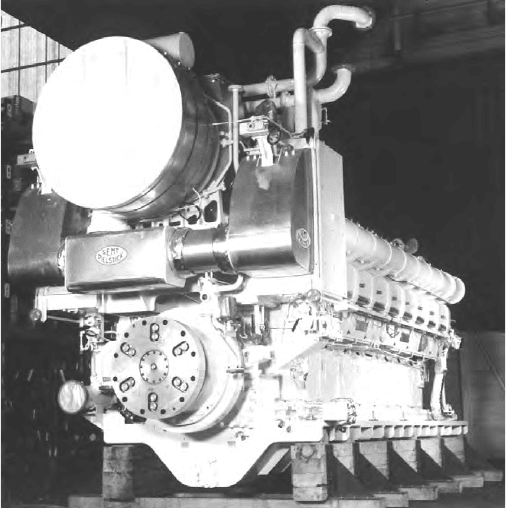
FiGurE 25.4 SEMT Pielstick 18PC2-6B engine, rated at 11 340 kW
640 SEMT Pielstick (MAN Diesel Group)
The cylinder liner (Figure 25.7) is similar to that of the PC2-6, the smaller
water jacket avoiding the direct contact of cooling water with the engine block
and hence the possibility of corrosion.
The composite piston design (Figure 25.8) is the same as that of the PC20.
Its steel head is without valve recesses to promote a uniform temperature dis-
tribution and thus limit thermal stresses; and the light alloy skirt has stepped
bosses to reduce mechanical stresses under combustion pressure.
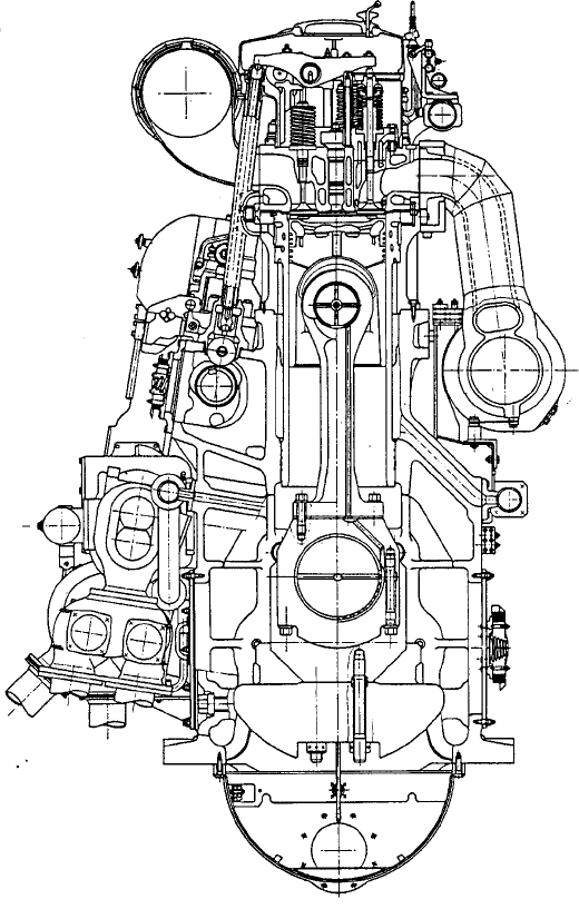
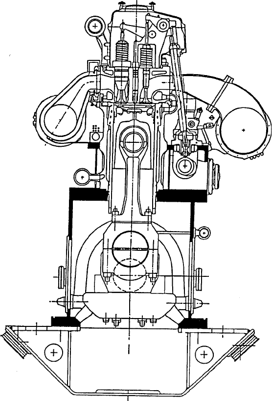
FiGurE 25.5 Cross-section of PC20L engine
PC2-6B design 641
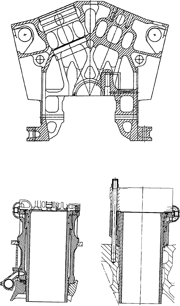
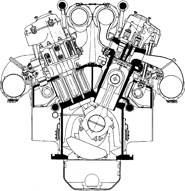
FiGurE 25.6 Cross-section of PC2-6B engine crankcase
Old design New Design
FiGurE 25.7 Comparison of crankcase, water jacket and cylinder liner arrangement
for PC2-6B engine and its predecessor
642 SEMT Pielstick (MAN Diesel Group)
Only two compression rings (formerly three) are featured in the five-ring
pack which, in conjunction with a honed liner, was designed to foster low
lubricating oil consumption. An inspection of the pistons after endurance test-
ing of a three-cylinder prototype engine revealed a ‘very good’ bearing pic-
ture for the skirt, without any contact marks between head and liner despite the
reduction in skirt length under the piston pin.
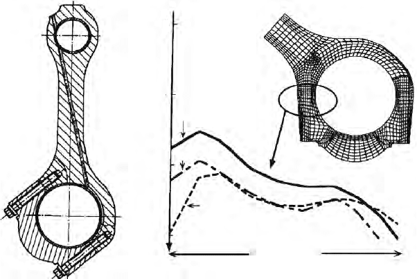
An exhaustive study of the connecting rod design (Figure 25.9) was dic-
tated by the increased inertia forces resulting from the longer stroke. The key
concerns were reliability and the prevention of fretting on the serration. The
main differences with the PC2-6 rod design are a higher tightening force at the
big end cap and larger bolts, which have been moved 10 mm outwards from
the bore. The effectiveness of the modifications was confirmed by an endur-
ance test on the prototype engine under extremely severe conditions (600 rev/
min). A subsequent inspection revealed no trace of fretting on the serration.
A modified crankshaft—with a main journal diameter increased to 350 mm
and crankpin diameter increased to 330 mm—was also deemed necessary in
view of the impact of a longer stroke and higher peak pressure on the bending
and torsional stresses as well as on the bearing operating conditions. The larger
diameter main journal maintains the oil film thickness and specific pressure at
similar levels to the PC2-6. Despite the larger crankpin diameter, the connecting
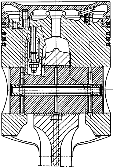
FiGurE 25.8 Two-part stepped boss piston of PC2-6B engine. Note the two com-
pression rings
rod big end bearings are slightly more loaded than those of the PC2-6: the
15 per cent higher loading is largely compensated by improved bearing shell
technology (Rillenlager-type shells).
A modified cylinder head design was introduced to improve the pressure dis-
tribution on the gasket, the main modifications involving fireplate local reinforce-
ments and repositioning of the side wall closer to the gasket circle. The highest
temperature measured on the fireplate (between the exhaust valves) during tests
of the prototype was, at 280°C, identical to that found on the PC20 engine.
PC2-6B Design Details
Frame: a stiff nodular cast iron crankcase construction.
Cylinders: each cylinder, including a water jacket and bore-cooled liner, is
fitted into the crankcase. Only the upper part of the liner is cooled, avoiding
any flow of water in the crankcase and hence possibility of corrosion.
Crankshaft: the one-piece forged unit rests on underslung main bearings fit-
ted with thin bearing shells. A temperature sensor is fitted on each main bear-
ing, preventing the development of shell bearing abnormality.
Connecting rods: the bevel-cut big end cap is secured by serrations on the
rod. In V-type engines the connecting rods of a cylinder pair are mounted side-
by-side on the same crankpin.
Piston: the composite-type piston comprises a steel crown (‘shaker’ oil
cooled) and a light alloy skirt of the stepped boss type to reduce stresses under
peak combustion pressure. The floating piston pin permits free rotation. The
five-ring pack includes two compression rings while two spring-loaded scraper
rings control lube oil consumption, their position in the upper part of the skirt
facilitating easier piston and liner lubrication.
PC2-6B design 643
Normal compressive
stresses on upper cut
A B
B
A
0
−50
−100
−150
MPa
Tightening
Tightening
+ combustion forces
Tightening
+ inertia forces
Upper cut width
FiGurE 25.9 PC2-6B engine connecting rod design and big end calculations

644 SEMT Pielstick (MAN Diesel Group)
Cylinder head: a vermicular cast iron component attached to the water
jacket and to the liner by eight tie-bolts anchored in the crankcase bosses.
Valves: both inlet and exhaust valves have a tight guide bush and the
exhaust valves feature a turning device. The entire water flow across the cyl-
inder head passes through the exhaust valve cages, substantially decreasing the
valve seat temperature.
Fuel injection: the injectors are cooled by a separate freshwater system.
The fuel pumps provide a pressure exceeding 1000 bar.
Camshaft: the bearings are secured with four bolts directly below the injec-
tion pump supports, an arrangement which avoids the transmission of injection
stresses to the crankcase. Each camshaft and its bearings can be removed later-
ally from the side of the engine. The fuel pump driving gear design secures a
low contact pressure between cam and roller.
Turbocharging: a patented MPC system represents a compromise between
impulse and constant pressure systems, and also fosters easier maintenance of
piping and expansion bellows.
Comparison of PC2.6-2 and PC2-6B parameters
PC2.6-2 PC2-6B
Bore, mm 400 400
Stroke, mm 460 500
Swept volume, dm
3
57.8 62.8
Max. combustion pressure, bar 137 (V-cyl)
142 (L-cyl)
150 (V-cyl)
150 (L-cyl)
Nominal power, kW/cyl 550 615
Speed, rev/min 500/514/520 500/514/520
Mean piston speed, m/s 7.7–8.0 8.3–8.6
Mean eective pressure, bar 22.9 23.5
Specic fuel consumption, g/kW h 183 182
PC2-6B LoW-PoLLuTANT VErSioN
In creating a low-pollutant version of the PC2-6B engine, SEMT Pielstick
aimed to find a compromise between low emission levels, first cost and run-
ning cost using proven solutions. The following nitrogen oxides (NOx) reduc-
tion techniques, investigated earlier on other prototype engines, were applied:
l Increased compression ratio: raised to 14.8 instead of 12.7:1 on the
standard engine.
l Retarded fuel injection: 4° before TDC instead of 11°.
l Water/fuel emulsion injection: 30 per cent/70 per cent ratio.
l Injection rate modification: an injector nozzle with nine 0.76 mm dia-
meter holes instead of the standard nine 0.72 mm holes.
l Turbocharger matching modification: rematched to increase slightly the
combustion air excess.
PC4-2B DESiGN
The last version of the 570 mm bore PC4 series, the PC4-2B design, had a
660 mm stroke and developed 1325 kW/cylinder at 430 rev/min on a mean effec-
tive pressure of 22 bar. The production programme embraced V10-, 12-, 16- and
18-cylinder models covering a power band up to 23 850 kW (Figure 25.2 and
Figure 25.10). A specific fuel consumption of 176 g/kW h was quoted. Progressive
improvements benefited the PC4 design after the first example entered service in
1977, the refinements focusing on the exhaust and inlet manifolds, exhaust valves,
fuel injection system, crankshaft and camshafts. The PC4-2 featured a 620 mm
stroke and the PC40L (Figure 25.11) a stroke of 750 mm and a running speed of
375 rev/min.
PC4-2B design 645
FiGurE 25.10 Cross-section of PC4-2B engine
646 SEMT Pielstick (MAN Diesel Group)
The key features of the PC4-2B engine include:
l A one-piece welded steel engine frame with a steel plate oil sump
mounted on the bottom.
l A bore-cooled cylinder liner of special cast iron located inside a cast
iron water jacket, avoiding contact between the cooling water and the
engine frame. Cooling of the liner’s upper part was calculated to reduce
thermal stresses.
l A one-piece underslung crankshaft of chromium molybdenum forged
steel; each main bearing is fixed by two vertical and two horizontal
FiGurE 25.11 Cross-section of PC40L engine
tie-bolts, fostering a weight reduction for the frame. A temperature
sensor is installed on each main bearing to prevent shell bearing
abnormalities.
l Composite-type pistons embrace a steel crown and light alloy skirt, with
a floating-type piston pin. The crown is oil cooled by the shaker effect.
l Forged alloy steel connecting rods with a wide big end and stepped boss
small end to secure low bearing pressures.
l The cast iron cylinder head is fixed to the water jacket and to the liner
by eight studs screwed into the frame bosses. It incorporates two inlet
and two exhaust valves, a fuel valve, an indicator valve, a safety valve
and a starting valve.
l Heat-resistant steel inlet valves exploit the two-guides solution while the
Nimonic exhaust valves have sealed guides. All water flowing across the
cylinder head runs through the exhaust valve cages, significantly reduc-
ing the valve seat temperature. All the valves are provided with Rotocap
rotating devices.
l Camshaft bearings are fixed directly under the fuel injection pump
brackets, avoiding the transmission of injection stresses to the frame.
l A large fuel injection pump diameter and short piping underwrite a high
injection pressure achieving fine fuel pulverization even at low load;
complete and clean combustion of the heaviest residual fuels with a high
asphaltene content is promoted. The fuel pump plunger and barrel can
be exchanged through the pump’s upper part without dismantling the
pump body. The weight of the dismountable equipment is 20 kg. The
fuel injectors are cooled by a separate freshwater circuit.
l The patented MPC turbocharging system was the best compromise
between pulse and constant pressure systems, according to SEMT
Pielstick. Air coolers could be supplied with two banks of tubes, one of
which could be deployed to heat air when the engine operates at low load.
See Chapter 30 for SEMT Pielstick PA series high-speed engines.
PC4-2B design 647
649
C h a p t e r | t w e n t y s i x
Sulzer (Wärtsilä)
IntroduCtIon
A successful medium-speed engine programme embracing the 200 mm bore
S20, 400 mm bore ZA40S and 500 mm bore ZA50S designs was offered by
Switzerland-based New Sulzer Diesel before becoming part of the Wärtsilä
Corporation. All were eventually phased out of the new Finnish parent’s port-
folio, the last examples of Sulzer four-stroke technology—V12- and V16-
cylinder ZA40S engines—being delivered in 2007 for a large cruise ship
propulsion project.
The Sulzer S20, ZA40S and ZA50S designs, covering an output range from
460 kW to 21 600 kW for propulsion and auxiliary power duties, were released
for operation on fuels with viscosities up to 700 cSt (Figure 26.1).
The modern four-stroke Z-engines matured from a 400 mm bore family
founded by the ZH40 two-stroke medium-speed engine, designed in the early
1960s and installed in icebreakers, ferries and cruise ships. The uniflow-scavenged
Four-stroke trunk-piston engines
ZA40S
bhp
Speed 400 500 600 700 800 900 1000 rev/min
30000
20000
10000
5000
2000
1000
ZA50S
20000
15000
10000
5000
2000
1000
500
25000
kW
AT25
S20U
FIgure 26.1 Power/speed ranges of Sulzer medium-speed engine designs