Woodyard D. (ed.) Pounders Marine diesel engines and Gas Turbines
Подождите немного. Документ загружается.

670 Wärtsilä
Wärtsilä Diesel’s medium-speed engine programme was progressively
extended in the 1980s and 1990s with smaller and larger bore heavy fuel-burning
models to create the programme outlined in Table 27.1. The more recent designs
are the Wärtsilä 32 (a more modern longer stroke derivative of the Vasa 32), the
Wärtsilä 64 (the world’s most powerful medium-speed engine) and the Wärtsilä
50DF dual-fuel engine (derived from the Wärtsilä 46 design). Wärtsilä 20 and 32
engines are produced at the Vasa factory in Finland, while the Wärtsilä 26, 38,
46 and 64 engines are assigned to Wärtsilä Italia in Trieste. All the designs, apart
from the W64, are now available optionally with common rail (CR) fuel injection.
The various designs introduced features now widely used by other four-
stroke enginebuilders, Wärtsilä citing: side-mounted one-cylinder camshaft
sections; four cylinder head bolts for large engines; 1500 bar-plus fuel injec-
tion pressure; and a ‘hot box’ for fuel injection pumps and pipes. Advanced
machining systems allowed comprehensive integration of fluid systems within
the engine block and the creation of multi-functional structural elements, sig-
nificantly reducing the overall number of components.
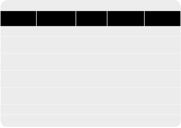
Maximum cylinder pressure limits beyond 200 bar have been pursued by
the company (Figure 27.1), exploiting nodular cast iron piston skirts with
forced piston skirt lubrication: part of the oil for cooling the piston crown is
forced out through four nozzles leading to an annular oil distribution groove,
fostering well-controlled lubrication and hence increased reliability and
reduced liner wear. Thick-pad bearing technology has benefited engines oper-
ating with high cylinder pressures.
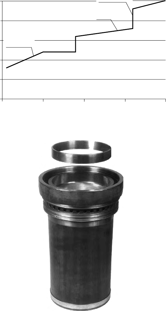
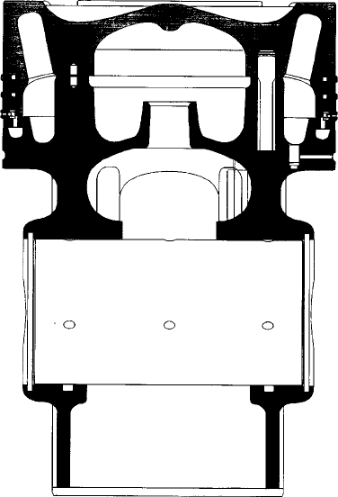
A three-ring piston pack is standard for Wärtsilä engines as is an anti-pol-
ishing ring at the top of the cylinder liner (Figure 27.2). The function of the lat-
ter ring is to calibrate the carbon deposits on the piston top land to a thickness
Table 27.1 Wärtsilä medium-speed engines
Design Bore/Stroke
(mm)
Output
(kW/cyl)
Speed
(rev/min)
Cylinders
W20 200/280 200 720–1000 4, 6, 8, 9L
W26 260/320 340 900/1000 6, 8, 9L/12,
16V
W32 320/400 500 720/750 6, 7, 8, 9L/12,
16, 18V
W38B 380/475 725 600 6, 8, 9L/12,
16V
W46C 460/580 1000 500/514 6, 8, 9L/12,
16V
W46F 460/580 1200 600 6, 7, 8, 9L/12V
W64L 640/900 2150 333 6, 7, 8L
Anti-polishing ring
Bar
250
200
150
100
50
0
1960 1970 1980 1990 2000
Piston ring
technology
Pressure-lubricated
piston skirt
Piston ring
technology
Figure 27.1 Contributions to the development of the maximum cylinder pressure
limit in Wärtsilä engines
Figure 27.2 Anti-polishing rings have beneted all Wärtsilä engines (W32 engine
liner shown)
Wärtsilä 671
672 Wärtsilä
small enough to prevent contact between the liner inner wall and the deposits
in any position of the piston. Bore polishing is reportedly eliminated and liner
lifetimes can be doubled, accompanied by cleaner piston ring areas and signifi-
cantly reduced lubricating oil consumption.
Low NOx combustion technology (whose principles are detailed in the sec-
tion Wärtsilä Vasa 32) can be applied to all current Wärtsilä models, reducing
noxious exhaust emissions without undermining fuel economy. The engines
can also be arranged for gas–diesel and dual-fuel burning installations (see
Chapter 2) and offered as part of group-supplied integrated Propac propulsion
packages embracing reduction gearing, propeller and control systems.
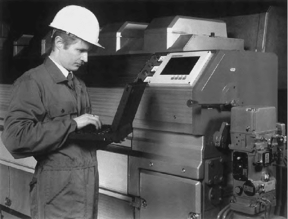
Wärtsilä has pioneered computer-based systems for engine control and
monitoring, condition monitoring and fault diagnosis, as well as multimedia
documentation and remote expert communication systems to support servicing
and maintenance (Figure 27.3).
WärTSiLä VASA 32
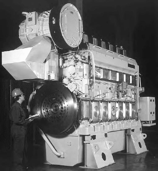
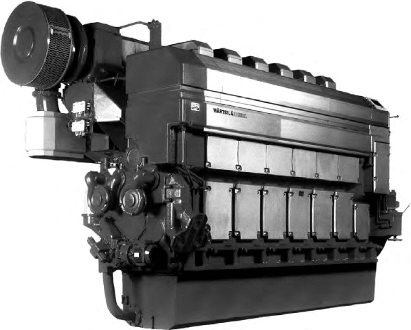
The 320 mm bore/350 mm stroke Vasa 32 engine (Figure 27.4) was designed
in the 1970s but benefited from progressive refinements yielding higher
power outputs, enhanced reliability and serviceability, and the acceptance
of fuels with higher CCAI numbers until the arrival in 1997 of the new gen-
eration Wärtsilä 32 (see section Wärtsilä 32). By that time, around 1900 Vasa
32 engines had been sold for marine service since the seagoing debut of the
design in 1978. Sustained demand nevertheless dictated continued production,
Figure 27.3 The engine computer is the ‘brain’ of the Wärtsilä engine Control
System (WeCS), shown here on a Wärtsilä 32
overlapping with the Wärtsilä 32 engine. The Vasa 32LN was produced in four, six,
eight and nine in-line and V12-, 16- and 18-cylinder models to cover propulsive
power demands from 1480 kW to 7380 kW at 720/750 rev/min. The D-rated ver-
sions offered 375 kW/cylinder while E-rated models yielded 410 kW/cylinder
with respective mean effective pressures of 21.9 bar and 24 bar.
The specification comprises the following main elements:
Engine block: designed for maximum overall stiffness and cast in one piece
for all cylinder numbers; arranged for underslung crankshaft; and direct instal-
lation on resilient mountings possible.
Crankshaft: forged in one piece; fully balanced; and optional torsional
vibration dampers.
Connecting rod: forged in alloy steel and machined; and diagonally stepped
split in the big end.
Bearings: designed for maximum wear resistance.
Cylinder liner: special cast iron; and bore cooling for efficient control of
liner temperature.
Piston/rings: composite piston with steel top and nodular cast iron skirt;
forced skirt lubrication; and ring set comprising three compression rings and
one oil scraper ring, all chromium plated.
Figure 27.4 The Wärtsilä Vasa 32 engine founded a family of heavy fuel-burning
designs
Wärtsilä Vasa 32 673
674 Wärtsilä
Cylinder head/valves: grey cast iron; absorbs the mechanical load with
a box section formed by an intermediate and an upper deck; mounted on the
engine block with hydraulically tensioned studs; twin inlet and twin exhaust
valves, all equipped with rotators; and water-cooled exhaust valve seats.
Camshaft: drop-forged one-cylinder shaft segments with integrated cams;
and bearing journals fitted to the camshaft segments with flange connections.
Fuel injection: one-cylinder pumps with built-in tappets; through-flow type
pumps for heavy fuel operation; uncooled nozzles; and all fuel-carrying equip-
ment located in a drained and insulated space (the hot box) which keeps the
system at operating temperature and ensures safety in the event of leakage.
Exhaust pipes: nodular cast iron, the entire system enclosed in an insulat-
ing box for safety.
Low NOx Vasa 32
The Vasa 32 engine in 1994 became the first in the Wärtsilä Diesel programme
to be released with low NOx combustion technology, a key measure calling for
the compression ratio to be increased from 12 to 14:1 to secure a sufficiently
high compression temperature. The smaller combustion space dictated reshap-
ing of the piston crown and the cylinder cover flame plate to allow for the fuel
jets and good air/fuel mixing.
A new piston was developed for the higher maximum firing pressure (raised
by 10 bar to 165 bar). Efficient cooling of the alloyed steel crown of the compos-
ite piston was secured by applying the cocktail shaker principle. The piston pin
diameter was increased by 10 per cent to match the higher cylinder pressure. The
three-ring concept (as opposed to the original four-ring set) was also adopted
following good experience on the Wärtsilä 46 engine, the two compression rings
benefiting from a special wear-resistant chrome-ceramic coating (Figure 27.5).
The stiff bore-cooled cylinder liner was equipped with an anti-polishing
ring to keep carbon and ash build-up on the piston top land thin enough to pre-
vent contact between the liner inner wall and the deposits, regardless of the
piston’s position. The liner lifetime is reportedly doubled and the lubricating
oil consumption halved to 0.6 g/kW h or less.
The increased cylinder pressure also required the connecting rod to be
changed from the original diagonally stepped two-piece component to a fully
machined three-piece design with a horizontally split big end bearing. The change
yields greater safety at increased load and eliminates the need to interfere with
the big end bearing assembly when overhauling the piston; a disadvantage is the
increased number of parts. The load-carrying capability of the big end bearing
was raised by switching from an SnSb or SnAl to a BiAl material type.
Only a minor modification to the cylinder head was necessary: a slight
reshaping of the flame plate to provide more space for the fuel jets.
The fuel injection system was redesigned to handle demands for an increased
injection rate and improved atomization. As a result, the fuel cam is faster
and provides higher lift to compensate for the reduced plunger bore/stroke ratio.
The injection valve opening pressure was raised from 350 bar to 600 bar, mainly
to improve atomization at the start and stop of injection, and to maintain the
higher injection pressure needed for a shorter injection period and reduced igni-
tion delay. Improved part- and low-load performance was apparent, along with
reduced NOx formation and fuel consumption. Test results showed it was poss-
ible to reach an NOx level of 11 g/kW h, a 30 per cent reduction compared with
a standard Vasa 32 engine (IMO’s limit is 12 g/kW h NOx at 720/750 rev/min).
At the same time, the specific fuel consumption was lowered from 187 g/kW h
to 180 g/kW h while maintaining a reasonable combustion pressure of 165 bar,
only 10 bar higher than that of a standard Vasa 32 engine.
Wärtsilä Diesel also developed a planetary gear with controls to replace the
standard intermediate gear of the camshaft transmission. The arrangement allowed
a retarded fuel injection mode to be temporarily engaged while the engine was in
operation to meet modest local NOx emission limits (up to 30 per cent reduction
on normal emission levels at the expense of a rise in fuel consumption).
WärTSiLä 32
A new generation 320 mm bore model was introduced to the market in 1997,
the Wärtsilä 32 exploiting a longer stroke (400 mm) than its Vasa 32 predeces-
sor and incorporating design features established on the Wärtsilä 20, 26, 38 and
46 engines (detailed later in this chapter). A higher output than its predecessor
Figure 27.5 Composite piston of Vasa 32 low NOx engine designed for increased
combustion pressure and low friction
Wärtsilä 32 675
676 Wärtsilä
was offered (460 kW/cylinder at 750 rev/min on a mean effective pressure
of 22.9 bar) to give a power range up to 8280 kW from in-line six, eight and
nine and V12-, 16- and 18-cylinder versions. (The programme now includes a
seven-cylinder model.)
Scope for future specific power rises was demonstrated by the test engine
operating comfortably on an mep of 31 bar. A higher rating was subsequently
released (500 kW/cylinder at 750 rev/min on an mep of 24.9 bar) to extend
the power range to 9000 kW. A specific fuel consumption of 173–180 g/kW h
(without engine-driven pumps) is quoted, depending on nominal output or opti-
mal point operation.
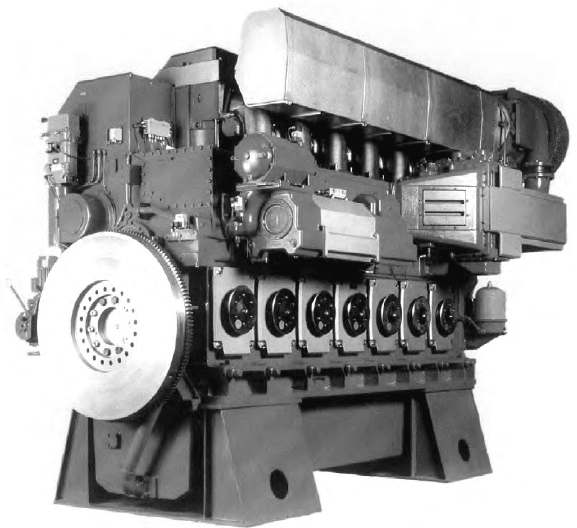
Although slightly taller and heavier than the Vasa 32, the Wärtsilä 32 is more
compact and has a better power/weight ratio. Integration reduced the number of
components in the new engine by 40 per cent compared with its forerunner and
contributed to a neater look and lower production costs (Figure 27.6). Ducts for
water and oil are incorporated in the engine block, and low-pressure fuel pipes
were replaced by ducts integrated in the injection pump design.
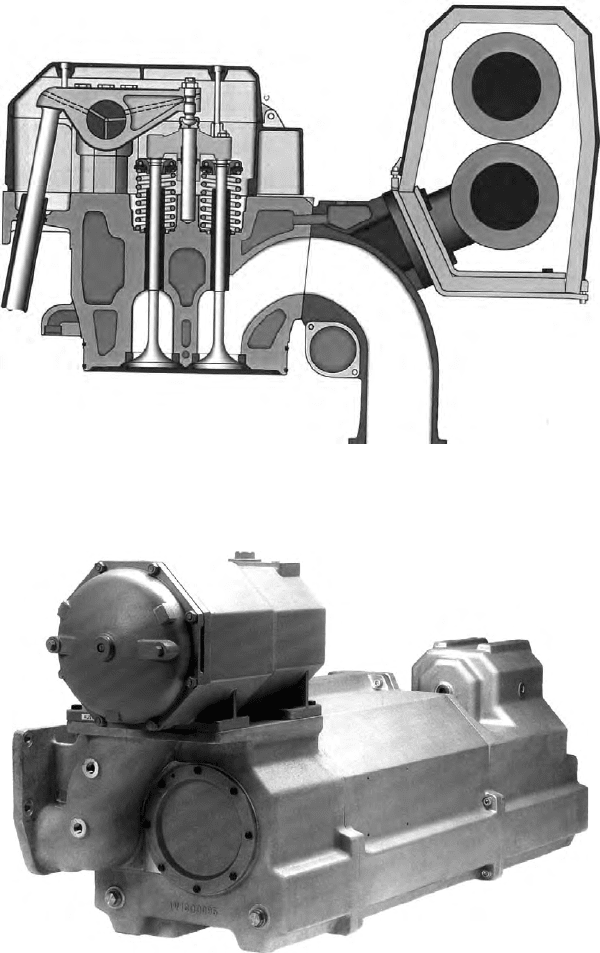
A substantial reduction in the number of joints to be broken during engine
overhauls resulted. Further attention was paid to easing maintenance. The
multi-duct (Figure 27.7) containing the water system and the exhaust and air
piping, for example, stays in place when the cylinder head is lifted; the joints
for starting air, oil and return fuel are slide-in connections; and, as there is no
real jacket water, only a limited amount of water has to be drained when main-
taining the cylinder unit. Ergonomic refinements were also pursued: the rocker
Figure 27.6 engine-driven pumps are standard for the Wärtsilä 32; note the clean
lines achieved by integrated duct systems which eliminate external piping
arm cover is suspended on hinges and stays in place when the rocker arms of
the injector are attended. Service pumps, including the pre-lubricating pump,
are arranged on the engine along with a lubricating oil module which incorpo-
rates an automatic back-flushing filter (Figures 27.8 and 27.9).
Figure 27.7 The multi-duct remains in place when the cylinder head is lifted
(Wärtsilä 32 engine)
Figure 27.8 Lubricating oil module for mounting on the Wärtsilä 32 engine
Wärtsilä 32 677
678 Wärtsilä
The low-pressure fuel line comprises drilled channels in cast parts clamped
firmly on the engine block, these parts consisting of the pump housing, the tap-
pet housing, the fuel transfer housing and the multi-cover. For easy assembly/
disassembly, the parts are connected to each other with slide connections. Both
the whole low-pressure and high-pressure systems are housed in a fully cov-
ered compartment. The high-pressure system is designed and endurance tested
at 2000 bar, and the injection pressure is around 1800 bar. With a wear-resistant
low-friction coating on the fuel plunger, no lubricating oil is required for the
pump element. The profiled plunger geometry allows the clearance between
plunger and barrel to be kept small, thereby allowing only a minimum of oil to
pass down the plunger; this small leakage is collected and returned to the fuel
system. Any likelihood of fuel mixing with the lube oil is eliminated.
The turbocharging system is specified to suit the requirements of each
engine application from these standard options: pulse system, single pipe
exhaust (Spex) system and Spex system with exhaust waste gate and air bypass.
The systems are designed for minimum flow losses on both exhaust and air
sides, the interface between engine and turbocharger streamlined to avoid all
the adaption pieces and piping often used in the past.
The Wärtsilä Engine Control System (WECS) serving the Wärtsilä 32 measures
a range of parameters and undertakes safety monitoring of the main bearing and
Figure 27.9 Lubricating oil module mounted on the side of a Wärtsilä 32 in-line
cylinder engine
cylinder liner temperatures, as well as individual exhaust valve monitoring. In the
case of the V18-cylinder model, for example, the computer-based system measures
97 temperatures, 10 pressures, four speeds, three positions and seven levels. It also
controls starting and stopping, the low-temperature (LT) thermostatic valve, waste
gate and bypass valves, and slow turning, and interfaces with external systems.
WärTSiLä 20
Introduced in 1992, the 200 mm bore/280 mm stroke Wärtsilä 20 engine
(Figure 27.10) was designed primarily as a genset drive to replace the long-
established Wärtsilä Vasa 22 but small-ship propulsion installations have also
been logged. An output per cylinder of 130 kW to 165 kW was initially offered,
depending on the nominal speed (720–1000 rev/min), but subsequent power
rises took the rating to 180 kW/cylinder (end-1998) and 200 kW/cylinder at
1000 rev/min (2003). The rating increases were underwritten by designing all
key components for a maximum cylinder pressure of 200 bar; engines are cur-
rently released with a P
max
of 170 bar.
The W20 series now embraces four-, six-, eight- and nine-cylinder models
covering a maximum continuous output range from 720 kW to 1800 kW. Up
to 24 000 h between overhauls have been achieved by engines running on light
fuel oils.
A flat fuel consumption curve, with the lowest point preferably at part load, is
desirable for an auxiliary engine which seldom operates at full load and may often
run at a very low load. This was addressed in the Wärtsilä 20 design by optimiz-
ing the cylinder dimensions in conjunction with modern turbocharging technol-
ogy; adopting a pulse charging system; and exploiting a high cylinder pressure.
Physically, the Wärtsilä 20 was intended to be shorter and lower than any
existing engine in its performance class, with advantages in ease of installation
and maintenance. The nodular cast iron engine block was designed for maxi-
mum overall stiffness and local stiffness around the upper part of the cylinder
liner, and to incorporate a number of cast-in or machined water and oil chan-
nels in pursuit of component integration. The camshaft bearings are directly
housed in the block as is the camshaft gear train at the flywheel end of the
engine. Provision is made for five engine-driven pumps (three are standard).
A four-point support configuration underwritten by the overall stiffness of the
engine is especially attractive for resilient mounting, and the screwed-on feet
arrangement offers considerable freedom in foundation design.
The four-screw cylinder head and box-cone design is another Wärtsilä
tradition retained to achieve even sealing pressure and prevent liner deforma-
tion under high cylinder pressures. It also secures ample space for large inlet
and exhaust channels which are necessary for good gas exchange. The head
is mounted on the engine block with hydraulically tensioned studs, and is
arranged to house two inlet and two exhaust valves, all equipped with rotators;
the exhaust valve seats are water cooled. A starting air motor for all engine
cylinder configurations was specified in contrast to traditional direct starting by
Wärtsilä 20 679