Woodyard D. (ed.) Pounders Marine diesel engines and Gas Turbines
Подождите немного. Документ загружается.

680 Wärtsilä
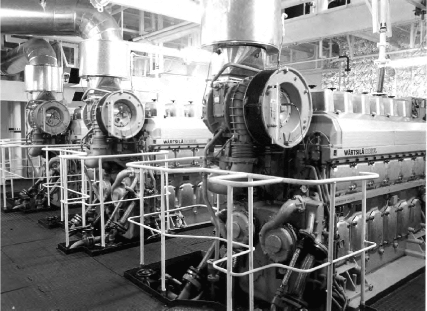
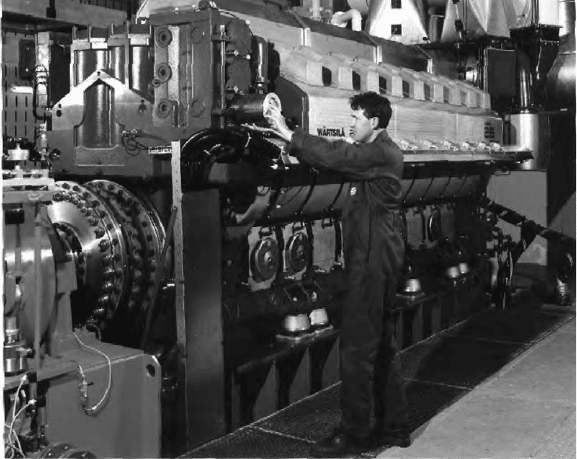
Figure 27.10 Three Wärtsilä 6L20-powered gensets in the engineroom of a feeder container ship
air injection into the combustion chamber, contributing to optimized cylinder
head stiffness and valve performance.
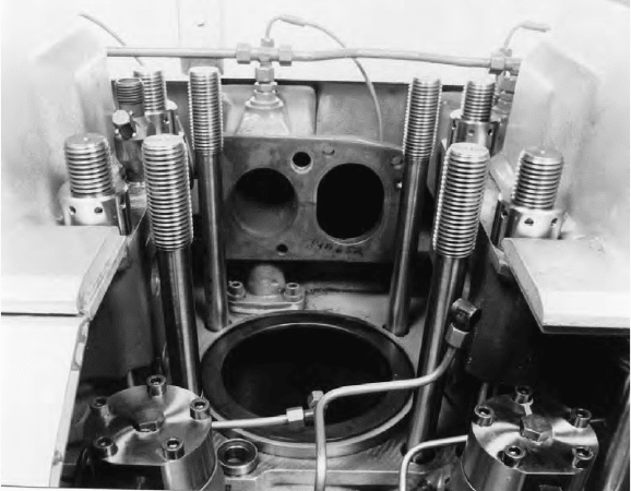
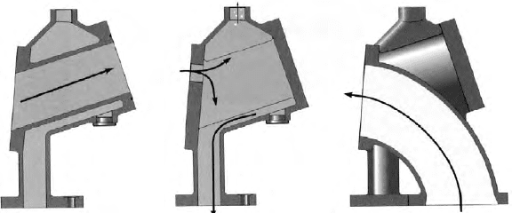
An innovation in the W20 design was a multi-functional duct between the
cylinder head and the engine block (Figure 27.11). The multi-duct houses the
air duct from the air receiver to the cylinder head (the air duct creates the initial
swirl which helps to achieve optimum part-load combustion) and incorporates
the exhaust gas channel. The cooling water from the cylinder head is led to a
cast-in channel in the engine block through the multi-duct. The multi-duct is
also the support for the exhaust pipes, remaining in place when the cylinder
head is removed to ease maintenance.
A ‘distributed water flow’ pattern is used to effect cooling of the exhaust
valves and cylinder head flame deck. An even temperature distribution results
from increasing the flow velocities on the exhaust side in general and around
the exhaust valve seat rings in particular.
The wear-resistant cast iron cylinder liner was designed for minimum
deformation thanks to its own stiffness and support from the engine block. It
was also important to tune the inner wall temperature to a level just above the
sulphuric acid dew point; this was addressed by creating an increased tangen-
tial cooling water flow velocity just below the liner collar. The risk of bore pol-
ishing is eliminated by an anti-polishing ring at the upper part of the liner.
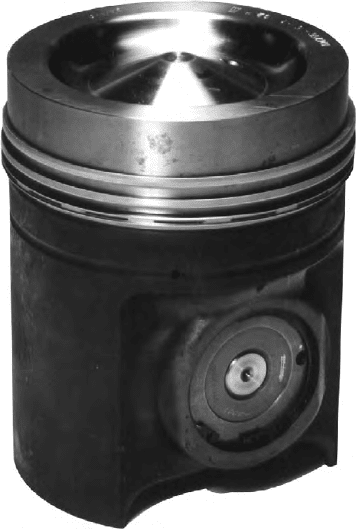
A traditional Wärtsilä concept was retained for the composite piston
(Figure 27.12) but refined for a smaller bore engine operating on heavy fuel: a
nodular cast iron skirt, steel crown and pressurized skirt lubrication. Two com-
pression rings and a spring-loaded oil scraper ring are located in the crown,
Figure 27.11 The multi-duct of the Wärtsilä 20 engine facilitates maintenance of
the cylinder components
Wärtsilä 20 681
682 Wärtsilä
the efficiency of a three-ring concept having been proven in the Wärtsilä 46
engine. (Most of the frictional loss in a reciprocating combustion engine origi-
nates from the piston rings; a three-ring pack is considered optimal by Wärtsilä
with respect to function and efficiency.) Each ring is chromium plated and
dimensioned and profiled for its individual task. The top ring benefits from a
special wear-resistant coating.
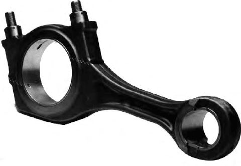
A connecting rod of forged and machined alloy steel with a stepped split
line lower end similar in design to that used in the Vasa 32 engines allows the
maximum pin diameter while still making it possible to pull the rod through
the cylinder liner (Figure 27.13). The advantage cited over the conventional
straight, oblique split line is an increase in pin diameter of at least 15 per cent,
a key factor in an engine designed for high combustion pressures. The fully
balanced crankshaft is forged in one piece and amply dimensioned for reliable
bearing performance. A small cylinder distance facilitates thin webs and large
bearing surfaces. A low bearing load and optimized balancing of the rotating
masses secure good oil film thicknesses at all engine loads and speeds.
The low-pressure fuel system is an integrated part of the injection pump
achieved via a multi-functional housing which acts as a housing for the single-
cylinder pump, a fuel supply line along the whole engine, a fuel return line from
each pump, a housing for the pneumatic overspeed trip device and guidance
Figure 27.12 Wärtsilä 20 engine composite piston with nodular cast iron pressure-
lubricated skirt and steel crown
for the valve tappets. The high-pressure fuel line is also fully enclosed with
an alarm for possible leakages, and all fuel-carrying parts are housed in a
fully covered compartment (hot box). The high-pressure side is designed for a
2000 bar injection pressure although the pressure used is around 1500 bar. The
pump element itself features a solution to eliminate cavitation erosion. The fuel
injection valve is designed for uncooled nozzles which are heat treated for low
wear and high heat resistance.
A traditional two-circuit cooling water system incorporates a hot circuit for
jacket water and a cold circuit for air-cooling and oil cooling. The inverse cool-
ing principle introduced earlier by Wärtsilä on the cold circuit side has report-
edly proven valuable for engine operation on low-quality heavy fuels at part
load. A stepless electronically controlled version was developed for standard fit-
ment to the W20 engine. The two pumps serving the cooling systems are engine
driven. The high-temperature (HT) cooling system is fully integrated into asso-
ciated engine components, virtually eliminating the use of pipes. Supply and
return channels are cast into the engine block while the pump cover and turbo-
charger support hold the connections between pump and engine block.
The system temperature is kept at a high level (about 95°C) for safe igni-
tion/combustion of low-quality heavy fuels at low loads. An engine-driven
pump of the cassette type is standard. The LT cooling system is also fully inte-
grated with the engine components (engine block, pump cover, air and lubricat-
ing oil cooler housings) and served by an engine-driven pump of the same type
as in the HT system. System temperature is electronically controlled as a func-
tion of engine load. The charge air temperature is optimized at every operating
point by heating the charge air with heat from the lubricating oil according to a
pre-set curve programmed into the electronic board.
The lubricating oil system is grouped compactly into two adjacent modules
at the flywheel end: one contains the cooler thermostatic valves and filters, and
Figure 27.13 The connecting rod of the Wärtsilä 20 engine incorporates a stepped
split
Wärtsilä 20 683
684 Wärtsilä
the other is a pump unit with a pre-lubricating pump and an engine-driven main
pump. The filter arrangement comprises three individual filter chambers which
can be switched off one by one when replacing the filter cartridge. A ‘safety mesh’
is also incorporated in each chamber. The paper-type filter cartridges are horizon-
tally positioned to facilitate proper cleaning of the chamber before a new cartridge
is installed. Centrifugal filters fitted for further filtration of the lubricating oil also
serve as the oil condition indicator.
A pulse turbocharging system was considered the best choice for an engine
designed for installations normally subject to frequent load variation and sud-
den load application. All cylinder configurations are served by an optimized
pulse system; no additional solutions are required for part-load operation.
The control and safety system is based on two cabling modules, one on each
side of the engine, and sensors of the ‘low mass’ type to avoid possible vibra-
tion damage. The sensors are prefabricated with the correct cable length and a
connector for connection to the cabling module. The modules in turn are con-
nected with multi-pin type connectors to the engine control unit (ECU) which is
resiliently mounted on the engine. Incorporated in the ECU is instrumentation
for local reading of engine and turbocharger speed, exhaust temperature after
each cylinder and after the turbocharger, an operating hour counter and elec-
tronic boards for speed measuring and charge air temperature control. Plug-in
connectors are provided for connecting the ECU to an external control system.
New W20 Layout
Seven years after Wärtsilä 20 engine production started, some design revi-
sions were made, mainly involving the ancillary equipment and with the aim
of improving environmental friendliness and adaptability to customer needs.
The main components, such as pistons, bearings and crankshaft, remained
untouched. The new layout was introduced at end-2000.
A drawback of the original layout was the paper cartridges used for lube
oil filtration. The number of filter cartridges per engine varied between two and
four, depending on the cylinder configuration. A typical genset installation of
three 9L20 engines running for 5000 h annually on heavy fuel oil would there-
fore generate hazardous waste in the shape of 100 used cartridges a year. The
main objective in revising the engine layout was to eliminate this waste and the
high cost of new filters for ship owners.
A completely new oil module was designed to enable the use of a fully auto-
matic back-flushing lube oil filter incorporating elements of seamless sleeve fab-
ric with HT resistance. An overhaul interval of 1 year is recommended, and the
expected filter lifetime is 4 years. The channels directing the fluids to the ther-
mostatic valves for the LT water and lubricating oil are integrated in the bracket
for the filter and the cooler. A horizontal position for the filter was chosen
because of space limitations and maintenance benefits. The filter housing drains
automatically when the engine is stopped so that any overhaul inside the filter is
easier, and the risk of foreign particles entering the clean side is minimal.
The oil cooler design was also changed from a tube type to a brazed-plate
heat exchanger. The cooler needs no outer casing and its cooling capacity varies
with the number of plates (the height of the cooler); this makes it possible to use
one bracket for all engine cylinder configurations. The same basic oil module is
used on both LF (auxiliary) and LD (main) engines; it is simply rotated 180°.
The number and size of non-machined parts, after the oil filter, were reduced
significantly to minimize the risk of foreign particles entering the system. Since
the Wärtsilä 20 cannot be equipped with running-in filters, to prevent damage to
the bearings or crankshaft during test runs, this redesign was necessary to allow
uninterrupted production. A dual drive, turbine-driven centrifugal oil filter is used
for removing particles from the flush oil coming from the automatic filter. Both
dry and wet oil sumps are available. The main oil pump was moved to the front
of the engine to optimize the suction arrangement for every installation type.
The charge air cooling module was redesigned to fit both versions of the
engine. A self-supporting flange sealing was selected to eliminate the prob-
lems with sealing the cooler insert on the original design. The same cooler and
the outlet duct are used on both LD and LF engines. The compressor washing
arrangement is integrated in the water box for the cooler on the LD engine.
Also integrated in the design was the possibility to have a water mist catcher.
The water and fuel connections were moved to the sides of the engine to
improve the pipe layout and the support for the pipes. No piping disturbs the
overhaul space since all the pumps are arranged at the front of the engine.
Among the options are a direct-driven sea water pump, 100 per cent power
take-off at both ends, WECS digital control system, fully integrated standby
connections for water, fuel and lube oil, and fuel flexibility (light and heavy)
possible for all engine types.
The old engine block design with loose feet (to make installation more
flexible) had proved unnecessary in practice as it was useful in only a handful
of applications. The feet were thus integrated with the engine block casting to
reduce cost; the option to use loose feet was nevertheless retained and wider
feet were designed to create a more effective resilient mounting. The main oil
channel is machined in the engine block to reduce both labour and material
costs. The charge air receiver wall was provided with two openings since the
charge air duct can be placed at either end of the engine.
A major disadvantage of the Wärtsilä 20 engine for propulsion applications was
that the turbocharger could only be mounted at its free end. It was therefore decided
to make it possible for the turbocharger to be located at either end on the six- to
nine-cylinder models, the main contenders in the small-ship propulsion market.
WärTSiLä 26
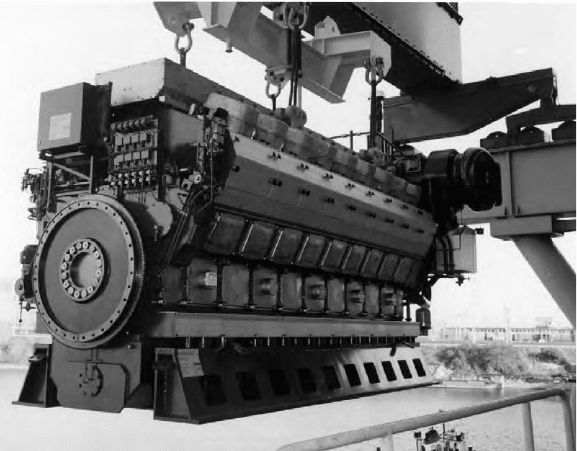
The 260 mm bore/320 mm stroke Wärtsilä 26 engine (Figure 27.14) was
launched in 1995 as an eventual replacement for the SW28 model in the Stork-
Wärtsilä Diesel medium-speed programme. The design is characterized by a high
power density and the capability to run on heavy fuel up to 730 cSt viscosity. An
Wärtsilä 26 685
686 Wärtsilä
advanced crankshaft design, significantly reducing the distance between cylin-
ders, and a short connecting rod limiting the height of the engine contributed to a
short and low overall configuration.
Propulsion and genset drive applications are now targeted by six, eight
and nine in-line and V12- and V16-cylinder models covering an output band
from around 1950 kW to 5440 kW at 900–1000 rev/min. Mean effective pres-
sures range from 24 bar to 25.5 bar, depending on heavy fuel or marine die-
sel oil operation, with power outputs up to 325 kW/cylinder (900 rev/min) and
340 kW/cylinder (1000 rev/min).
Most of the design work was executed at Stork-Wärtsilä Diesel in The
Netherlands. The designers defined five key objectives: high reliability; low
fuel consumption and emissions; simple, space-saving installation; multiple
applications and fuel choices; and low operating cost per kilowatt. The goals
were addressed by combining technology developed specifically for the appli-
cation with design features of three earlier ‘new generation’ engines in the
Wärtsilä Diesel programme: the medium-speed W38 and W20 series and the
high-speed W200 series (Chapter 30).
High reliability was sought from the incorporation of structural and com-
ponent designs proven in these and other Wärtsilä engines, such as thick-pad
bearing technology and pressurized skirt lubrication. Extended times between
overhauls and enhanced lifetimes were also targeted.
Compact, more simple and accessible installations are addressed by inte-
grating ancillary support equipment (pumps, filters, coolers and thermostats) on
Figure 27.14 The W26 engine in V18-cylinder form; it is possible to change the lube
oil lter while the engine is running
the engine. Piping is eliminated from outside the engine; the channels for lubri-
cating oil and cooling water are all incorporated in the block and other castings;
and the inlet air receiver is also completely integrated in the engine block casting.
A multi-duct (Figure 27.15) combines several functions, providing a connection
between the inlet air receiver and the inlet port of the cylinder head, a flow channel
for exhaust gases and a cooling water channel. It also supports the exhaust system
and facilitates dismantling of the cylinder head without disturbing that system.
The pursuit of integration reduced the overall number of Wärtsilä 26 engine
components by around 30 per cent compared with the SW28 design.
Engine length was saved by giving the crankshaft undercuts. The radii in
the transition from the crank web to the crankpin and from the crank web to the
journal are included in the web itself. As a result, it was possible to keep the
distance between the cylinders short and, at the same time, specify an optimum
bearing length. A beneficial effect on the oil film thickness of the bearings, and
hence their durability, was gained. The fully balanced crankshaft, suitable for
full power output to be taken off either end, was designed for maximum overall
rigidity and moderate bearing loads.
The highest possible rigidity was also sought from the cylinder head design
which features a conical intermediate deck and provides optimum support to
the flame deck. The flame deck has drilled coolant channels to inhibit large
thermal stresses. The exhaust valve seats are water-cooled and the valve tem-
peratures measured by sensors.
Flanged cylinder liners with tangential cooling water flow are installed. The
liner is supported symmetrically at the top by the cylinder block and sized so
that the temperature on the inner wall remains high enough to prevent LT cor-
rosion yet low enough to ensure good lubrication. This design, proven on the
Wärtsilä 20 engine, makes drilled coolant holes unnecessary; as a result, a thin-
ner liner wall can be used. An anti-polishing ring at the top of the liner is spec-
ified to prevent contact between the piston crown and the liner, thus avoiding
any bore polishing by combustion residues. High resistance to wear is further
fostered by elements in the alloy material of the liner. The anti-polishing ring
also contributes to a reported lubricating oil consumption of under 0.5 g/kW h.
Exhaust gas Cooling water Charge air
Figure 27.15 Schematic diagram of multi-duct connected to the cylinder head
(Wärtsilä 26 engine)
Wärtsilä 26 687
688 Wärtsilä
The composite piston consists of an oil-cooled steel crown with three rings
(two ceramic chromium-plated compression rings and an oil distributor ring) and
a nodular cast iron skirt. Crown and skirt are fastened to each other by one cen-
tral bolt to foster an even, symmetrical load distribution (another feature whose
effectiveness had been demonstrated in the Wärtsilä 20 engine). Pressurized skirt
lubrication secures excellent tribological behaviour at high cylinder pressures.
A connecting rod with a horizontal split was developed for the Wärtsilä
26 engine, exploiting the finite element method to optimize the component
with regard to maximum stiffness and minimum mass. Key merits cited for the
resulting design are a short length, high rigidity, reliability and low mass (and
consequently a smaller load on the bearings). The rod is drilled with a single
hole without plugs for delivering lubricating oil to the piston.
An injection pressure of 2000 bar, necessary for fine atomization of the fuel
and a short injection duration, is attained by closed barrel-type fuel pumps. Fuel
feed lines are integrated in the pump housing, and the fuel system is designed to
keep pressure pulses low. The high injection pressure dictated a very rigid cam-
shaft made of single-cylinder sections connected to each other by bearing journals.
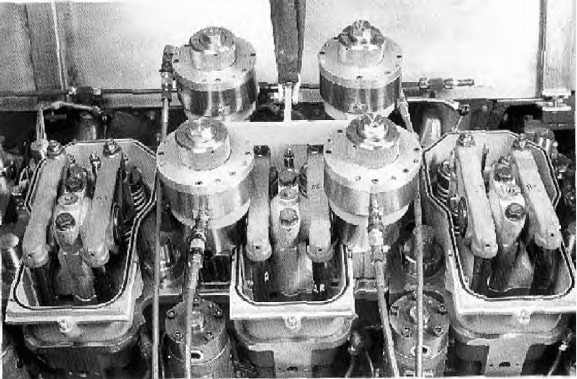
Design details facilitate easier inspection and maintenance routines. The
stud bolts for the cylinder head, connecting rod and main bearing are hydrauli-
cally tensioned (Figure 27.16). When the head is removed, the multi-duct sup-
ports the exhaust gas piping and the insulation cover.
The seals of the cooling water pump can be replaced without dismantling the
pump itself. Replacement or inspection of the piston rings is possible without
disassembly of the liner: the piston can be partially removed from the liner for
this purpose.
The fuel pumps can be replaced quickly and simply without taking apart
the low-pressure piping and the tappets; the pump can be taken from the engine
Figure 27.16 The stud bolts for the cylinder head (shown here) as well as those for
the connecting rod and main bearing of the W26 engine are hydraulically tensioned
and overhauled under clean workshop conditions. Both air cooler and lubricat-
ing oil cooler are of the insert type, allowing convenient removal for cleaning,
and it is possible to change the oil filters while the engine is running.
A Wärtsilä-designed computer-based ECU protects the engine, warning
against possible problems before damage occurs. Signals from sensors are
transmitted to the unit via a CAN bus connection comprising a single cable
from one end of the engine to the other.
WärTSiLä 38
The 380 mm bore/475 mm stroke W38 design was developed by Wärtsilä
Diesel’s Dutch subsidiary Stork-Wärtsilä Diesel as a replacement for its age-
ing TM410 engine (see Chapter 28), filling a power gap in the group portfolio
between the Vasa 32 and W46 designs. The W38 series was introduced in 1993
with a specific rating of 660 kW/cylinder at 600 rev/min to cover a power band
from 3960 kW to 11 880 kW with six, eight and nine in-line and V12-, 16- and
18-cylinder models (Figure 27.17).
The design was distinguished by a new combustion philosophy applied to
achieve a high thermal efficiency and reduced NOx emissions (down by 50–70
per cent) without compromising fuel economy. The key parameters are a
stroke/bore ratio of 1.25:1, a maximum cylinder pressure of up to 210 bar and
a maximum fuel injection pressure of 1500 bar. Such parameters provide the
flexibility to select a compression ratio, injection timing and injection rate that
allow the desired low NOx values to be attained.
A completely new fuel injection system was developed with the following
characteristics: suitable for continuous 1500 bar injection pressure; closed barrel;
Figure 27.17 V18-cylinder version of the Wärtsilä 38 engine
Wärtsilä 38 689