Yu W., LaBoube R.A. Cold-Formed Steel Design
Подождите немного. Документ загружается.

WELDED CONNECTIONS 275
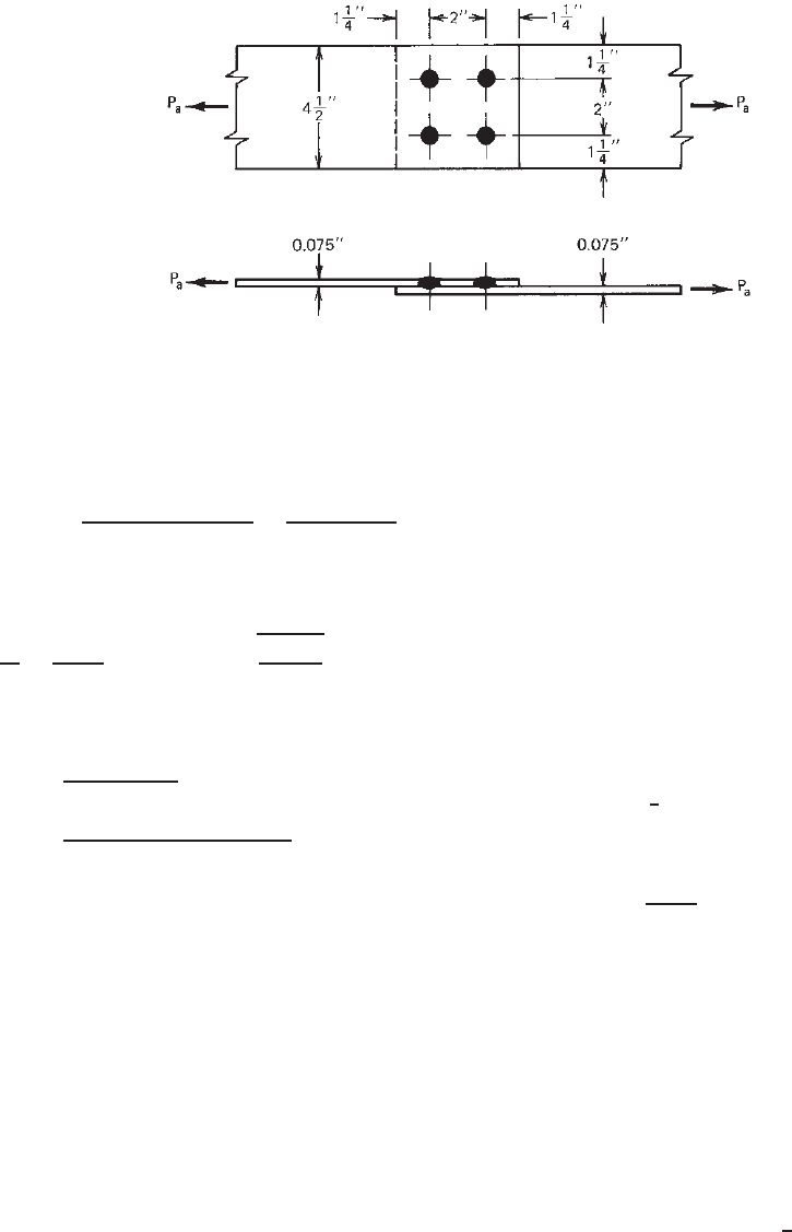
Figure 8.19 Example 8.1.
c. Shear Capacity of Welds. By using Eq. (8.26) and
E60 electrodes,
P
a3
=
(4πd
2
e
/4)(0.75F
xx
)
=
π(0.4125)
2
(0.75 ×60)
2.55
= 9.43 kips
d. Strength of Connected Sheets Around Welds
d
a
t
=
0.675
0.075
= 9 <
0.815
29,500
60
= 18.07
By using Eq. (8.27a)
P
a4
=
4(2.20td
a
F
u
)
=
4(2.20)(0.075)(0.675)(60)
2.20
= 12.15 kips
On the basis of the above considerations, the allow-
able load for the ASD method is the smallest value,
that is, 9.09 kips, which is governed by the tensile
load for yielding of steel sheets.
B. LRFD Method
As the first step of the LRFD method, the AISI requirements
for using arc spot welds should be checked as the ASD
method. From items 1–5 for the ASD method, the layout
of the spot welds are satisfied with the AISI requirements.
The design strength φP
n
for the LRFD method is based
on the following considerations:
a. Tensile Load for Steel Sheets. BasedonSectionC2of
the AISI specification:
i. For yielding [Eq. (6.2)],
φ
t
P
n
= φ
t
T
n
= φ
t
(A
g
F
y
)
= (0.90)(4.5 ×0.075)(45) = 13.67 kips
ii. For fracture away from the connections [Eq. (6.3)],
φ
t
P
n
= φ
t
T
n
= φ
t
(A
n
F
u
)
= (0.75)(4.5 ×0.075)(60) = 15.19 kips
Use φ
t
P
n
= 13.67 kips.
b. Tensile Load Based on End Distance (e = 1.25 in.).
Using Eq. (8.25) for four spot welds (F
u
/F
y
> 1.08),
φP
n
= φ(4)(eF
u
t)
= (0.70)(4)(1.25 × 60 ×0.075) = 15.75 kips
c. Shear Capacity of Welds. By using Eq. (8.26) and E60
electrodes,
φP
n
= φ(4)
1
4
πd
2
e
(0.75F
xx
)
= (0.60)(π )(0.4125)
2
(0.75 × 60) = 14.43 kips
d. Strength of Connected Sheets Around Welds. Since
d
a
/t < 0.815
√
E/F
u
, use Eq. (8.27a),
φP
n
= φ(4)(2.20td
a
F
u
)
= (0.70)(4)(2.20 ×0.075 × 0.675 ×60)
= 18.71 kips
Based on the above four considerations, the controlling
design strength is 13.67 kips, which is governed by the
tensile load for yielding of steel sheets.
According to the load factors and load combinations
discussed in Section 3.3.2.2, the required strength for the
given dead load–live load ratio of
1
5
is computed as follows:
P
ul
= 1.4P
D
+ P
L
= 1.4P
D
+ 5P
D
= 6.4P
D
[Eq. (3.5a)]
where P
D
= applied load due to dead load
P
L
= applied load due to live load

276 8 CONNECTIONS
and
P
u2
= 1.2P
D
+ 1.6P
L
= 1.2P
D
+ 1.6(5P
D
) = 9.2P
D
[Eq. (3.5b)]
Use P
u
= 9.2P
D
.Byusing9.2P
D
= 13.67 kips,
P
D
= 1.49 kips
P
L
= 5P
D
= 7.45 kips
The allowable load based on the LRFD method is
P
D
+ P
L
= 1.49 +7.45 = 8.94 kips
It can be seen that the LRFD method permits a slightly
smaller allowable load than the ASD method. The differ-
ence between these two design approaches for this partic-
ular case is less than 2%.
Arc Seam Welds. For arc seam welds (Fig. 8.10), Section
E2.3 of the AISI North American Specification specifies
that the nominal shear strength (resistance) P
n
of an arc
seam weld is the smaller of the values computed by Eqs.
(8.31) and (8.32):
i. Nominal Shear Strength Based on Shear Capacity of
Weld
P
n
=
πd
2
e
4
+ Ld
e
0.75F
xx
(8.31)
ii. Nominal Shear Strength Based on Strength of
Connected Sheets
P
n
= 2.5tF
u
(0.25L + 0.96d
a
) (8.32)
For Eqs. (8.31) and (8.32),
= 2.55 (ASD)
φ = 0.60 (LRFD)
= 0.50 (LSD)
d = width of arc seam weld
L = length of seam weld not including circular ends (for
computation purposes, L should not exceed 3d)
The definitions of d
a
, d
e
, F
u
,andF
xx
and the require-
ments for minimum edge distance are the same as those for
arc spot welds.
Equation (8.31) is derived from Eq. (8.12) and Eq. (8.32)
is based on Eq. (8.13).
Fillet Welds. AccordingtoSectionE2.4oftheAISINorth
American Specification, the design strength of a fillet weld
in lap and T-joints should not exceed the values computed
by Eq. (8.33) for the shear strength of the fillet weld and by
Eq. (8.34) or Eq. (8.35) for the strength of the connected
sheets as follows:
i. Nominal Strength Based on Shear Capacity of Weld .
For t > 0.10 in. (3.8 mm),
P
n
= 0.75t
w
LF
xx
(8.33)
= 2.55 (ASD)
φ =
0.60 (LRFD)
0.50 (LSD)
ii. Nominal Strength Based on Strength of Connected
Sheets
a. Longitudinal Loading.WhenL/t < 25,
P
n
=
1 − 0.01
L
t
tLF
u
(8.34a)
= 2.55 (ASD)
φ =
0.60 (LRFD)
0.50 (LSD)
When L/t > 25,
P
n
= 0.75tLF
u
(8.34b)
= 3.05 (ASD)
φ =
0.50 (LRFD)
0.40 (LSD)
b. Transverse Loading
P
n
= tLF
u
(8.35)
= 2.35 (ASD)
φ =
0.65 (LRFD)
0.60 (LSD)
where P
n
= nominal strength of a fillet weld
L = length of fillet weld
t
w
= effective throat, =0.707w
1
or
0.707w
2
, whichever is smaller
w
1
, w
2
= leg size of fillet weld (Fig. 8.20)
The definitions of t, F
u
,andF
xx
are the same as those
used for arc spot welds. It should be noted that Eqs. (8.33),
(8.34), and (8.35) are based on Eqs. (8.14), (8.15), and
(8.16), respectively.
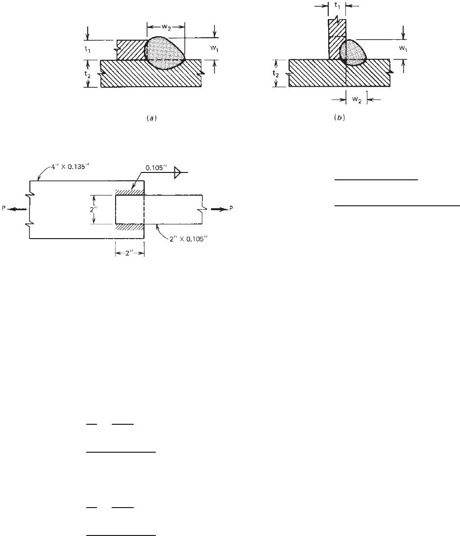
Example 8.2 Use the ASD method to determine the
allowable load for the welded connection using fillet welds,
as shown in Fig. 8.21. Assume that A570 Grade 33 steel
sheets and E60 electrodes are to be used.
WELDED CONNECTIONS 277
Figure 8.20 Leg sizes of fillet welds
1.4
:(a) lap joint; (b) t-joint.
Figure 8.21 Example 8.2.
SOLUTION. From Table 2.1, the yield point and the
tensile strength of A1011 Grade 33 steel are 33 and 52
ksi, respectively. The allowable load P can be determined
as follows:
1. Allowable Tensile Load for Steel Sheet. Based on
Section C2 of the AISI Specification:
i. For yielding [Eq. (6.2)],
P
al
=
T
n
t
=
A
g
F
y
1.67
=
(2.0 × 0.105)(33)
1.67
= 4.15 kips
ii. For fracture away from the connections [Eq. (6.3)],
P
al
=
T
n
t
=
A
n
F
n
2.00
=
(2.0 × 0.105)(52)
2.00
= 5.46 kips
Use P
a1
= 4.15 kips.
2. Allowable Load for Longitudinal Fillet Welds. Since
L/t = 2/0.105 = 19.05 < 25, use Eq. (8.34a),
P
L
=
[1 −0.01(L/t)]tLF
u
=
[1 −0.01(19.05)](0.105)(2)(52)
2.55
= 3.46 kips per weld
Using two longitudinal welds
P
a2
= 2P
L
= 2 × 3.46 = 6.92 kips
Because the thickness of steel sheet is less than 0.10
in., it is not necessary to use Eq. (8.33).
Since P
a1
<P
a2
, the allowable tensile load is governed
by the tensile capacity of steel sheet, that is,
P
a
= 4.15 kips
The use of the LRFD method can be handled in the same
way as Example 8.1.
Flare Groove Welds. On the basis of Section E2.5 of the
AISI North American specification, the nominal strength of
each flare groove weld should be determined as follows:
i. Nominal Strength Based on Shear Capacity of Weld.
For t > 0.10 in. (3.8 mm),
P
n
= 0.75t
w
LF
xx
(8.36)
= 2.55 (ASD)
φ =
0.60 (LRFD)
0.50 (LSD)
ii. Nominal Strength Based on Strength of Connected
Sheet
278 8 CONNECTIONS
(
c
)
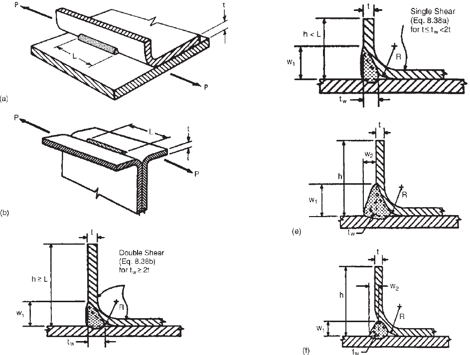
Figure 8.22 (a) Shear in longitudinal flare bevel groove
weld.
1.314,1.345
(b) Shear in longitudinal flare V-groove
weld.
1.314,1.345
(c) Flare bevel groove weld (filled flush to surface,
w
1
= R).
1.314,1.345
a. Transverse Loading (Fig. 8.14)
P
n
= 0.833tLF
u
(8.37)
= 2.55 (ASD)
φ =
0.60 (LRFD)
0.50 (LSD)
b. Longitudinal Loading (Figs. 8.22a–8.22f)
If t ≤ t
w
< 2t or if the lip height is less than the
weld length L,
P
n
= 0.75tLF
u
(8.38a)
If t
w
> 2t and the lip height is equal to or greater
than L,
P
n
= 1.50tLF
u
(8.38b)
(d)
Figure 8.22 (d) Flare bevel groove weld (filled flush to surface,
w
1
= R).
1.314
(e) Flare bevel groove weld (not filled flush to
surface, w
1
>R).
1.314
(f ) Flare bevel groove weld (not filled flush
to surface, w
1
<R).
1.134
Using Eqs. (8.37) and (8.38),
= 2.80 (ASD)
φ =
0.55 (LRFD)
0.45 (LSD)
In Eqs. (8.36) through (8.38),
P
n
= nominal strength (resistance) of flare groove
weld
h = height of lip
L = length of the weld
t
w
= effective throat of flare groove weld filled flush
to surface (Figs. 8.22c and 8.22d)
For flare bevel groove weld t
w
= 5/16R
For flare V-groove weld t
w
= 1/2R [3/8R when R >
1
/
2
in. (12.7 mm)]
WELDED CONNECTIONS 279
t
w
= effective throat of flare groove weld not filled
flush to surface = 0.707 w
1
or 0.707 w
2
, whichever
is smaller. (Figs. 8.22e and 8.22f )
t
w
= larger effective throat than those above shall be
permitted if measurement shows that the welding
procedure to be used consistently yields a large
value of t
w
R = radius of outside bend surface
w
1
,w
2
= legofweld(seeFigs.8.22e and 8.22f )
F
u
, F
xx
were defined previously
It should be noted that Eqs. (8.36), (8.37), and (8.38) are
derived from Eqs. (8.17), (8.18), (8.19), and (8.20).
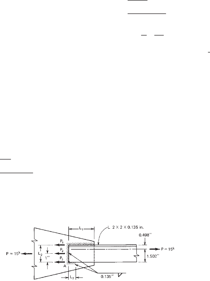
Example 8.3 Use the ASD method to design a welded
connection as shown in Fig. 8.23 for the applied load of
15 kips. Consider the eccentricity of the applied load. Use
A606 Grade 50 steel (F
y
= 50 ksi and F
u
= 70 ksi) and
E70 electrodes.
SOLUTION. Considering the eccentricity of the applied
load, it is desirable to place the welds so that their centroids
coincide with the centroid of the angle section. It should be
noted that weld L
1
is a flare groove weld, weld L
2
is a
transverse fillet weld, and weld L
3
is a longitudinal fillet
weld.
Let P
2
be the allowable load of end weld L
2
.Byusing
Eq. (8.35) for transverse fillet welds
P
2
=
tLF
u
=
(0.135)(2.0)(70)
2.35
= 8.04 kips
Taking moments about point A,
P(1.502) − P
1
(2.0) − P
2
(1.0) = 0
15(1.502) − P
1
(2.0) − 8.04(1.0) = 0
P
1
= 7.25 kips P
3
= P − (P
1
+ P
2
) 0
For the flare groove weld subjected to longitudinal
loading, with the assumption that t ≤ t
w
< 2t, the allow-
able load according to Eq. (8.38a) is
P
a
=
0.75tLF
u
=
0.75(0.135)(1)(70)
2.80
= 2.53 kips/in.
The required length L
1
is
L
1
=
P
1
P
a
=
7.25
2.53
= 2.87 in.
Use L
1
= 3in.
For weld length L
3
, use the minimum length of
3
4
in.
specified in Section 2.3.3.1 of the AWS code, even though
P
3
is approximately equal to zero.
8.3.3 Additional Design Information on Welded
Connections
The preceding discussion and design examples were based
on the AISI North American Specification. For addi-
tional information concerning details of welded connec-
tions, workmanship, technique, qualification, and inspec-
tion, the reader is referred to the AWS code.
8.96
In addition to the research work conducted at Cornell
and the design criteria being used in the United States,
other research projects on welded connections have been
conducted by Baehre and Berggren,
8.4
Stark and Soe-
tens,
8.22
Kato and Nishiyama,
8.23
Snow and Easterling,
8.99
and others. These references also discuss design considera-
tions and testing of welded connections. An economic study
of the connection safety factor has been reported by Lind,
Knab, and Hall in Ref. 8.24. Design information on tubular
joints can be found in Refs. 8.25–8.32 and 8.68–8.70.
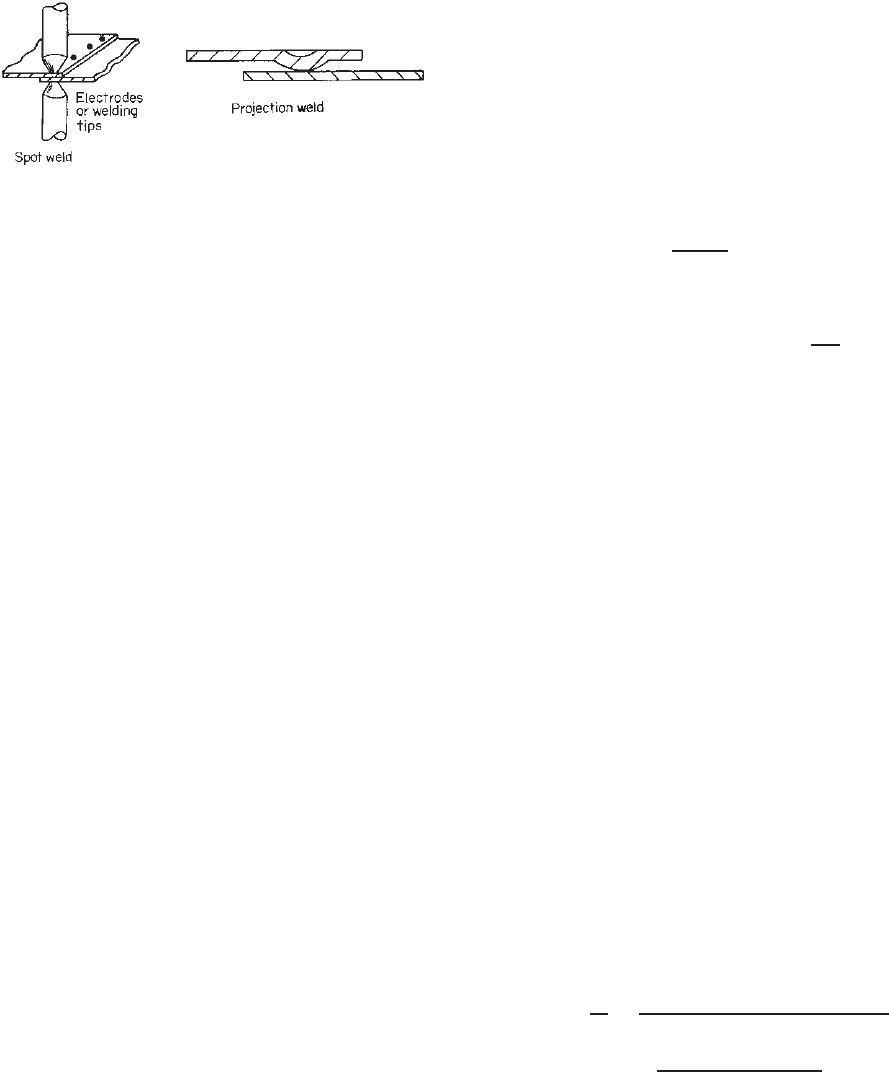
8.3.4 Resistance Welds
Resistance welds (including spot welding and projection
welding) are mostly used for shop welding in cold-formed
steel fabrication (Fig. 8.24).
Figure 8.23 Example 8.3.
280 8 CONNECTIONS
Figure 8.24 Resistance welds.
The nominal shear strengths for spot welding (Table 8.1)
are based on Section E2.6 of the 1996 AISI Specification,
which is based on Ref. 8.33 for outside sheets of 0.125 in.
or less in thickness and Ref. 8.34 for outside sheets thicker
than 0.125 in. The safety factor used to determine the
allowable shear strength is 2.5 and the resistance factor used
for the LRFD method is φ = 0.65. Values for intermediate
thicknesses may be obtained by straight-line interpolation.
The above tabulated values may also be applied to
pulsation welding and spot welding medium-carbon and
low-alloy steels with possibly higher shear strengths. It is
interesting to note that if the shear strength specified in the
AISI Specification is used for spot welding galvanized steel
sheets, a relatively larger safety factor may be obtained for
the ASD method.
8.35
It should be noted that special welding procedures may
be required for the welding of low-alloy steels. In all cases,
welding should be performed in accordance with the AWS
recommended practices.
8.33,8.34, 8.104
In 1999, the following equations for the nominal shear
strength of spot welds were developed to replace the tabu-
lated values given in Table 8.1
1.333
:
1. For 0.01 in. (0.25 mm) ≤ t < 0.14 in. (3.56 mm),
P
n
=
⎧
⎪
⎪
⎪
⎪
⎨
⎪
⎪
⎪
⎪
⎩
144t
1.47
(for t in inches and
P
n
in kips) (8.39a)
5.51t
1.47
(for t in mm and
P
n
in kN) (8.39b)
2. For 0.14 in. (3.56 mm) ≤ t < 0.18 in. (4.57 mm),
P
n
=
⎧
⎪
⎪
⎪
⎪
⎨
⎪
⎪
⎪
⎪
⎩
43.4t + 1.93 (for t in inches and
P
n
in kips) (8.40a)
7.6t + 8.57 (for t in mm and
P
n
in kN) (8.40b)
where t is the thickness of the thinnest outside sheet.
The upper limit of Eq. (8.39) was selected to best fit
the data provided in Table 2.1 of Ref. 8.33 and Table 1.3
of Ref. 8.34. Equation (8.40) is limited to t ≤ 0.18 in.
(4.57 mm) due to the thickness limit set forth in the AISI
North American Specification.
Table 8.1 and Eqs. (8.39) and (8.40) provide only the
nominal shear strength for spot welding. If the tensile
strength of spot welding is required, it can be obtained
either from tests or from the following empirical formulas
for tensile and shear strengths proposed by Henschkel
8.36
:
1. Tensile Strength
N = tF
u
D
a
F
u
− b
+ c − (f C + gMn)
2. Shear Strength
S = tF
u
D
α − β
C +
Mn
20
where N = tensile strength of spot welding
S = shear strength of spot welding
t = sheet thickness
F
u
= tensile strength of steel sheet
C = carbon content
Mn = manganese content
D = weld nugget diameter
a, b, c, f , g , α, β = coefficients determined from
test results (see Ref. 8.36 for
detailed information)
It should be noted that Henschkel’s study was based on
the following ranges of material:
1. Thickness of steel sheet: 0.008–0.500 in. (0.2–
12.7 mm)
2. Tensile strength of material: 37,500–163,800 psi
(258–1129 MPa)
3. Carbon content: 0.01–1.09%
4. Manganese content: 0.03–1.37%
From the above two equations, the relationship between
tensile and shear strengths of spot welding can be expressed
as follows:
N
S
=
a
(F
u
− b)(α − βC − 0.05βMn)
+
c − fC− gMn
α − βC − 0.05βMn
Using the constants given in Ref. 8.36, it can be seen
that for the steels specified in the AISI North American
Specification the tensile strength of spot welding is higher
than 25% of the shear strength.
See Example 8.8 for the design of welded connections
using resistance welds.

BOLTED CONNECTIONS 281
Table 8.1 Nominal Shear Strength for Spot Welding
1.314
Thickness of Nominal Shear Thickness of Nominal Shear
Thinnest Outside Strength per Thinnest Outside Strength per
Sheet (in.) Spot (kips) Sheet (in.) Spot (kips)
0.010 0.13 0.080 3.33
0.020 0.48 0.090 4.00
0.030 1.00 0.100 4.99
0.040 1.42 0.110 6.07
0.050 1.65 0.125 7.29
0.060 2.28 0.190 10.16
0.070 2.83 0.250 15.00
8.3.5 Shear Lag Effect in Welded Connections of
Members
When a tension member is not connected through all
elements, such as when an angle is connected through
only one leg, the stress distribution in the cross section
is nonuniform. This phenomenon is referred to as “shear
lag,” which has a weakening effect on the tensile capacity
of the member.
For the design of hot-rolled steel shapes, the AISC
Specification uses the effective net area A
e
for determining
the nominal strength. The effective net area is computed as
A
e
= UA
n
in which U is the reduction factor and A
n
is the net area.
For cold-formed steel design, the following Specifi-
cation Section E2.7 was added in the Supplement in
1999
1.333
and has been retained for subsequent editions of
the Specification
1.345
:
E2.7 Shear Lag Effect in Welded Connections of
Members Other Than Flat Sheets
The nominal strength of a welded member shall be determined
in accordance with Section C2. For fracture and/or yielding
in the effective net section of the connected part, the nominal
tensile strength, P
n
, shall be determined as follows:
P
n
= A
e
F
u
(8.41)
= 2.50 (ASD)
φ =
0.60 (LRFD)
0.50 (LSD)
where F
u
is the tensile strength of the connected part as
specifiedinSectionA2.1orA2.3.2andA
e
= AU is the
effective net area with U defined as follows:
1. When the load is transmitted only by transverse welds:
A = area of directly connected elements
U = 1.0
2. When the load is transmitted only by longitudinal welds
or by longitudinal welds in combination with transverse
welds:
A = gross area of member, A
g
U = 1.0 for members when the load is transmitted directly
to all of the cross sectional elements
Otherwise, the reduction coefficient U is determined
as follows:
(a) For angle members:
U = 1.0 −
1.20 ¯x
L
< 0.9 (8.42)
but U shall not be less than 0.4
(b) For channel members:
U = 1.0 −
0.36 ¯x
L
< 0.9 (8.43)
but U shall not be less than 0.5
where ¯x = distance from shear plane to centroid of the
cross section (Fig. 8.25)
L = length of longitudinal welds (Fig. 8.25)
The above design provisions were adapted from the AISC
design approach. Equations (8.42) and (8.43) are based
on the research work conducted by Holcomb, LaBoube,
and Yu at the University of Missouri-Rolla on bolted
connections.
6.24,6.25
8.4 BOLTED CONNECTIONS
The structural behavior of bolted connections in cold-
formed steel construction is somewhat different from that in
hot-rolled heavy construction, mainly because of the thin-
ness of the connected parts. Prior to 1980, the provisions
included in the AISI Specification for the design of bolted
connections were developed on the basis of the Cornell tests
conducted under the direction of George Winter.
8.37–8.40
These provisions were updated in 1980
1.4
to reflect the
results of additional research performed in the United
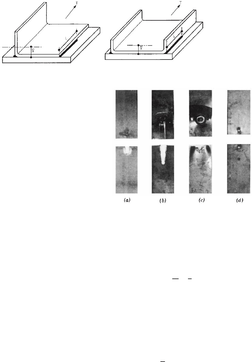
282 8 CONNECTIONS
Figure 8.25 Determination of ¯x for sections using fillet welds.
1.333,1.346
States
4.30,8.41–8.46
and to provide a better coordination with
the specifications of the Research Council on Structural
Connections
8.47
and the AISC.
1.148
In 1986, design provi-
sions for the maximum size of bolt holes and the allowable
tension stress for bolts were added in the AISI Specifica-
tion. The 1996 edition of the Specification combined the
ASD and LRFD design provisions with minor revisions.
The shear lag effect on bolted connections were considered
in the Supplement to the 1996 Specification. New bearing
equations were adopted in the 2001 edition
1.336
and retained
in the 2007 edition of the Specification.
8.4.1 Research Work and Types of Failure Mode
Since 1950, numerous bolted connections using thin sheets
with A307 bolts and A325 high-strength bolts have been
tested at Cornell University and other institutions. The
purposes of these research projects were to study the struc-
tural performance of bolted connections and to provide
necessary information for the development of reliable
design methods. A summary of this research is provided
by Yu
1.354
.
Results of tests indicate that the following four basic
types of failure usually occur in the cold-formed steel bolted
connections:
1. Longitudinal shearing of the sheet along two parallel
lines (Fig. 8.26a)
2. Bearing or piling up of material in front of the bolt
(Fig. 8.26b)
3. Tearing of the sheet in the net section (Fig. 8.26c)
4. Shearing of the bolt (Fig. 8.26d)
These four failure modes are also illustrated in Fig.
8.27. In many cases, a joint is subject to a combination of
different types of failure modes. For example, the tearing
of the sheet is often caused by the excessive bolt rotation
and dishing of the sheet material.
8.45,6.23
8.4.1.1 Longitudinal Shearing of Steel Sheets (Type
I Failure) When the edge distance e as shown in
Figure 8.26 Types of failure of bolted connections.
8.37
Figs. 8.27a and 8.28 is relatively small, connections
usually fail in longitudinal shearing of the sheet along two
parallel lines.
Research
1.354
has shown that for bolted connections
having small e/d ratios the bearing stress at failure can
be predicted by
σ
b
F
u
=
e
d
(8.44)
where σ
b
= ultimate bearing stress between bolt and
connected part, ksi
F
u
= tensile strength of connected part, ksi
e = edge distance, in.
d = bolt diameter, in.
Equation (8.44) is based on the results of bolted connec-
tion tests with the following parameters
8.46
:
Diameter of bolt d :
3
16
–1 in. (4.8–25.4 mm)
Thickness of connected part t: 0.036–0.261 in. (0.9–
6.6 mm)
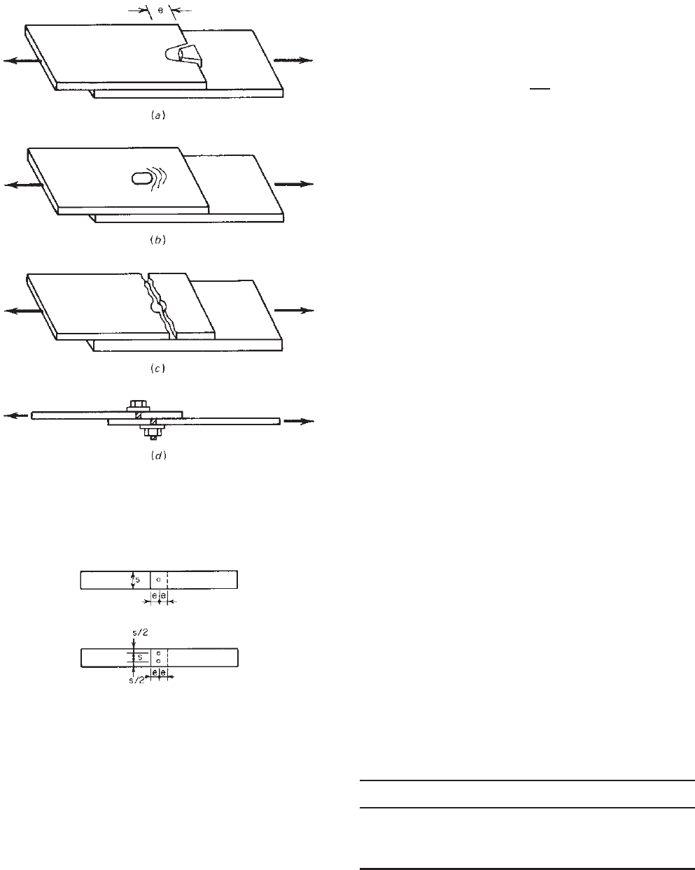
BOLTED CONNECTIONS 283
Figure 8.27 Types of failure of bolted connections: (a) longitu-
dinal shear failure of sheet (type I); (b) bearing failure of sheet
(type II); (c) tensile failure of sheet (type III); (d ) shear failure of
bolt (type IV).
Figure 8.28 Dimensions s and e used in bolted connections.
Edge distance e: 0.375–2.5 in. (9.5–63.5 mm)
Yield point of steel F
y
: 25.60–87.60 ksi (177–604 MPa,
1800–6150 kg/cm
2
)
Tensile strength of steel F
u
: 41.15–91.30 ksi (284–630 MPa,
2890–6420 kg/cm
2
)
e/d ratio: 0.833–3.37
d/t ratio: 2.61–20.83
F
u
/F
y
ratio: 1.00–1.63
The dimension of the specimens and the test results are
given in Ref. 8.45.
By substituting σ
b
= P
u
/dt into Eq. (8.44), Eq. (8.45)
can be obtained for the required edge distance e,
e =
P
u
F
u
t
(8.45)
This equation was also used for the specifications of the
Research Council on Structural Connections
8.47,8.48
and the
AISC.
1.148
8.4.1.2 Bearing or Piling Up of Steel Sheet (Type II
Failure) When the edge distance is sufficiently large (i.e.,
for large e/d ratios), the connection may fail by bearing
or piling up of steel sheet in front of the bolt, as shown
in Fig. 8.27b. Additional studies indicate that the bearing
strength of bolted connections depends on several param-
eters, including the tensile strength of the connected part,
the thickness of the connected part, the types of joints (lap
joints or butt joint), single-shear or double-shear conditions,
the diameter of the bolt, the F
u
/F
y
ratio of the connected
part, the use of washers, the “catenary action” of steel
sheets, and the rotation of fasteners. Equation (8.46) was
developed for determining the ultimate bearing capacity on
the basis of the applicable parameters. This equation was
developed from the available test data
8.105, 8.106
:
P
n
= Cm
f
dtF
u
(8.46)
where C = bearing factor, determined in accordance
with Table 8.2
m
f
= modification factor for type of bearing
connection determined in accordance with
Table 8.3
d = nominal bolt diameter
t = uncoated sheet thickness
F
u
= tensile strength of sheet.
It should be noted that the Eq. 8.46 is applicable only
when the deformation around the bolt holes is not a design
consideration. If the deformation around the bolt holes
is a design consideration, research has determined that
the nominal bearing strength is given by the following
Table 8.2 Bearing Factor C
1.345
Thickness, td/tC
0.024 ≤ t < 0.1875 d/t < 10 3.0
10 ≤ d/t ≤ 22 4 − 0.1(d /t)
d/t > 22 1.8

284 8 CONNECTIONS
Table 8.3 Modification Factor m
f
forTypeofBearing
Connection
1.345
Type of Bearing Connection m
f
Single-shear and outside sheets of double-shear
connection with washers under both bolt head
and nut
1.00
Single-shear and outside sheets of double-shear
connection without washers under both bolt
head and nut or only one washer
0.75
Inside sheet of double-shear connection with or
without washers
1.33
equation
6.25
:
P
n
= (4.64t +1.53) dtF
u
(with t in inches) (8.47a)
ForSIunits:
P
n
= (0.183t +1.53) dtF
u
(with t in mm) (8.47b)
All symbols were defined previously.
The above design equations were developed from the
research conducted at the University of Missouri-Rolla to
recognize the hole elongation prior to reaching the limited
bearing strength of a bolted connection.
6.24,6.25
The move-
ment of the connection was limited to 0.25 in. (6.4 mm),
which is consistent with the permitted elongation prescribed
in the AISC specification for hot-rolled steel shapes and
built-up members.
8.4.1.3 Tearing of Sheet in Net Section (Type III
Failure) In bolted connections, the type of failure by
tearing of the sheet in the net section is related to the stress
concentration caused by
1. The presence of holes
2. The concentrated localized force transmitted by the
bolt to the sheets
Previous tests conducted at Cornell University for
connections using washers under the bolt head and nut
have indicated that plastic redistribution is capable of
eliminating the stress concentration caused by the presence
of holes even for low-ductility steel.
8.39
However, if
the stress concentration caused by the localized force
transmitted by the bolt to the sheet is pronounced, the
strength of the sheet in the net section was found to
be reduced for connections having relatively wide bolt
spacing in the direction perpendicular to the transmitted
force. The effects of the d/s ratio on the tensile strength of
bolted connections with washers is discussed in Ref. 1.354.
An additional study conducted at Cornell on connections
using multiple bolts has shown that the sharp stress concen-
tration is much relieved when more than one bolt in line is
used and the failure in the net section in two-bolt (r =
1
2
)
and three-bolt (r =
1
3
) tests occurred at a much higher stress
than in a single-bolt (r = 1) connection. The following
formulas have been developed to predict the failure stress
in the net section:
σ
net
=
1 − 0.9r +3r
d
s
F
u
≤ F
u
when
d
s
≤ 0.3
(8.48)
σ
net
= F
u
when
d
s
> 0.3 (8.49)
where σ
net
= failure stress in net section, ksi
r = force transmitted by bolt or bolts at the
section considered divided by the force in
the member at that section
d = bolt diameter, in.
s = spacing of bolts perpendicular to line of
stress, in.
F
u
= ultimate tensile strength of steel sheets, ksi
The correlations between Eq. (8.48) and the test data is
discussed by Yu in Ref. 1.354. The test data reflects the
following parameters
8.46
:
Diameter of bolt d :
1
4
–1
1
8
in. (6.4–28.6 mm)
Thickness of steel sheet t: 0.0335–0.191 in. (0.9–4.9 mm)
Width of steel sheet s: 0.872–4.230 in. (22–107 mm)
Yield point of steel F
y
: 26.00–99.40 ksi (179–685 MPa,
1830–6990 kg/cm
2
)
Tensile strength of steel F
u
: 41.15–99.80 ksi (284–688 MPa,
2890–7020 kg/cm
2
)
d/s ratio: 0.063–0.50
d/t ratio: 3.40–21.13
When washers are not used and when only one washer
is used in bolted connections, the failure stress in the net
section σ
net
can be determined by
σ
net
=
1.0 −r + 2.5r
d
s
F
u
≤ F
u
(8.50)
The correlation between Eq. (8.50) and the test data is
presented by Yu in Ref. 1.354.
Research conducted at the University of Sydney revealed
that for flat sheet connections having multiple rows of bolts
in the line of force the strength reduction represented by
Eqs. (8.48) and (8.50) is not required.
8.107
8.4.1.4 Shearing of Bolt (Type IV Failure) A number
of double-shear and single-shear tests were performed at