Yu W., LaBoube R.A. Cold-Formed Steel Design
Подождите немного. Документ загружается.


NORTH AMERICAN DESIGN CRITERIA 255
for axial compression. This higher elastic buckling stress
for bending results from the beneficial effect of the stress
gradient that exists in bending. However, some investigators
have indicated that there is not much difference between the
critical stress in bending and that in axial compression.
3.84
The bending strength of closed cylindrical tubes has
been studied by Sherman
7.26
and Stephens, Kulak, and
Montgomery.
7.21
7.4.3 Local Buckling under Torsion
The theoretical local buckling stress of moderate-length
tubes subjected to torsion can be computed by
7.2
(τ
cr
)
torsion
=
0.596a
(1 − μ
2
)
5/8
E
t
R
5/4
R
L
1/2
= 0.632aE
t
R
5/4
R
L
1/2
(7.16)
where τ
cr
is the critical shear buckling stress due to torsion
and
a =
1 − μ
2
1 − μ
2
p
3/4
E
s
E
= 1.16
E
s
E
(7.17)
Previous studies indicate that the effect of imperfection
on torsional postbuckling is much less than the effect on
axial compression. Test data indicate that due to the effect
of initial imperfection the actual strength of the member is
smaller than the analytical result.
7.4.4 Local Buckling under Transverse Shear
In Ref. 7.2, Schilling suggests that in the elastic range the
critical shear buckling stress in transverse shear be taken as
1.25 times the critical shear buckling stress due to torsion,
that is,
(τ
cr
)
transverse shear
= 1.25 × 0.632aE
t
R
5/4
R
L
1/2
= 0.79aE
t
R
5/4
R
L
1/2
(7.18)
7.4.5 Local Buckling under Combined Loading
The following interaction formula may be used for any
combined loading
7.2
:
f
f
cr
+
τ
τ
cr
2
= 1 (7.19)
where f = actual computed normal stress
f
cr
= critical buckling stress for normal stress alone
τ = actual computed shear stress
τ
cr
= critical buckling stress for shear stress alone
7.5 NORTH AMERICAN DESIGN
CRITERIA
1.314,1.345
The AISI design criteria for closed cylindrical tabular
members w ere revised in the 1986 and 1996 editions of
the Specification on the basis of Refs. 1.158, 7.5, and 7.30.
In 1999, the design equation for determining the effec-
tive a rea was simplified.
1.333
The same design criteria were
retained in the 2007 edition of the North American Speci-
fication with rearrangement of section numbers and e dito-
rial revisions.
1.345
For additional information, the reader is
referred to Refs. 8.25–8.32.
7.5.1 Local Buckling Stress
Considering the postbuckling behavior of the axially
compressed cylinder and the important effect of the initial
imperfection, the design provisions included in the AISI
Specification were originally based on Plantema’s graphic
representation
7.27
and the additional results of cylindrical
shell tests made by Wilson and Newmark at the University
of Illinois.
7.28,7.29
From the tests of compressed tubes, Plantema found that
the ratio F
ult
/F
y
depends on the parameter (E/F
y
)(t/D),
in which t is the wall thickness, D is the mean diameter
of the closed tubes, and F
ult
is the ultimate stress or
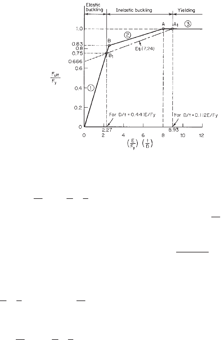
collapse stress. As shown in Fig. 7.7, line 1 corresponds
to the collapse stress below the proportional limit, line 2
corresponds to the collapse s tress between the proportional
limit and the yield stress (the approximate proportional
limit is 83% of F
y
at point B ), and line 3 represents the
collapse stress occurring at yield stress. In the range of line
3, local buckling will not occur before yielding, and no
stress reduction is necessary.
In ranges 1 and 2, local buckling occurs before the yield
stress is reached. In these cases the stress should be reduced
to safeguard against local buckling.
As shown in Fig. 7.7, point A represents a specific value
of (E/F
y
)(t/D) = 8, which divides yielding and local
buckling. Using E = 29.5 × 10
3
ksi (203 GPa or 2.07 ×
10
6
kg/cm
2
), it can be seen that closed tubes with D/t ratios
of no more than 0.125 E/F
y
are safe from failure caused
by local buckling. Specifically, Plantema’s equations are as
follows
7.4
:
1. For D/t < 0.125E/F
y
(yielding failure criterion
represented by line 3),
F
ult
F
y
= 1 (7.20)
2. For 0.125E/F
y
<D/t<0.4E/F
y
(inelastic buckling
criterion represented by line 2),
F
ult
F
y
= 0.031
E
F
y
t
D
+ 0.75 (7.21)
256 7 CLOSED CYLINDRICAL TUBULAR MEMBERS
Figure 7.7 Ultimate strength of cylindrical tubes for local buckling.
3. For D/t > 0.4E/F
y
(elastic buckling criterion repre-
sented by line 1),
F
ult
F
y
= 0.33
E
F
y
t
D
(7.22)
Based on a conservative approach, AISI specifies that
when the D/t ratio is smaller than or equal to 0.112E/F
y
,
the tubular member shall be designed for yielding.
This provision is based on point A
1
,forwhich(E/F
y
)
(t/D) = 8.93.
When 0.112E/F
y
<D/t<0.441E/F
y
, the design of
closed cylindrical tubular members is based on the local
buckling criteria. For the purpose of developing a design
formula for inelastic buckling, point B
1
was selected by
AISI to represent the proportional limit. For point B
1
,
E
F
y
t
D
= 2.27 and
F
ult
F
y
= 0.75 (7.23)
Using line A
1
B
1
, the maximum stress of tubes can be
represented by
F
ult
F
y
= 0.037
E
F
y
t
D
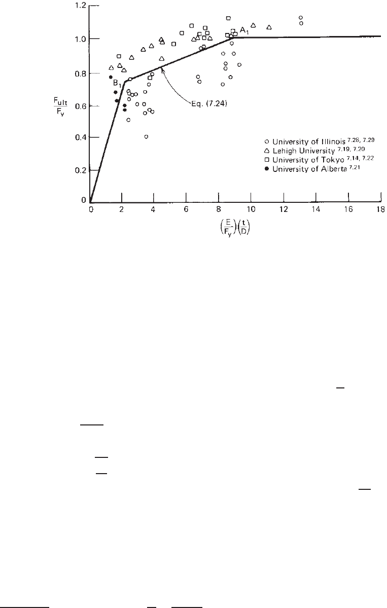
+ 0.667 (7.24)
The correlation between the available test data and Eq.
(7.24) is shown in Fig. 7.8.
Let A be the area of the unreduced cross section and A
0
be the reduced area due to local buckling; then
AF
ult
= A
0
F
y
(7.25)
or
A
0
=
F
ult
F
y
A (7.26)
Substituting Eq. (7.24) into Eq. (7.26), the following
equation can be obtained for D/t < 0.441E/F
y
:
A
0
=
0.037
(D/t)(F
y
/E)
+ 0.667
A ≤ A (7.27)
where D is the outside diameter of the closed cylindrical
tubular member.
7.5.2 Compressive Strength
When a closed cylindrical tubular member is subject to
a compressive load in the direction of the member axis
passing through the centroid of the section, the AISI design
provision was changed in 1996 and 1999 to reflect the
results of additional studies of closed cylindrical tubular
members to be consistent with Section C4 of the 1996
specification.
1.314
The following equations are now included
in Section C4.1.5 of the 2007 edition of the North American
Specification for determining the nominal axial strength P
n
of closed cylindrical tubular members having a ratio of
NORTH AMERICAN DESIGN CRITERIA 257
Figure 7.8 Correlation between test data and AISI criteria for local buckling of closed cylindrical
tubes under axial compression.
outside diameter to wall thickness, D/t, not greater than
0.441E/F
y
1.314,1.333, 1.345
:
P
n
= F
n
A
e
(7.28)
where P
n
is the nominal axial strength of the member and
F
n
is the flexural buckling stress determined as follows: For
λ
c
≤ 1.5,
F
n
= (0.658
λ
2
c
)F
y
(7.29)
For λ
c
> 1.5,
F
n
=
0.877
λ
2
c
F
y
(7.30)
where
λ
c
=
F
y
F
e
(7.31)
In the above equations F
e
is the elastic flexural buck-
ling stress determined according to Section C4.1.1 of the
specification and A
e
is the effective area of the cylindrical
tubular member under axial compression determined as
follows
1.333, 1.343, 1.345
:
A
e
= A
o
+ R(A − A
o
) (7.32)
R = F
y
/(2F
e
) ≤ 1.0 (7.33)
A
o
=
0.037
(DF
y
)/(tE)
+ 0.667
A ≤ A for
D
t
≤
0.441E
F
y
(7.34)
where A = area of full unreduced cross section
D = outside diameter of closed cylindrical tube
E = modulus of elasticity of steel
F
y
= yield stress
t = thickness
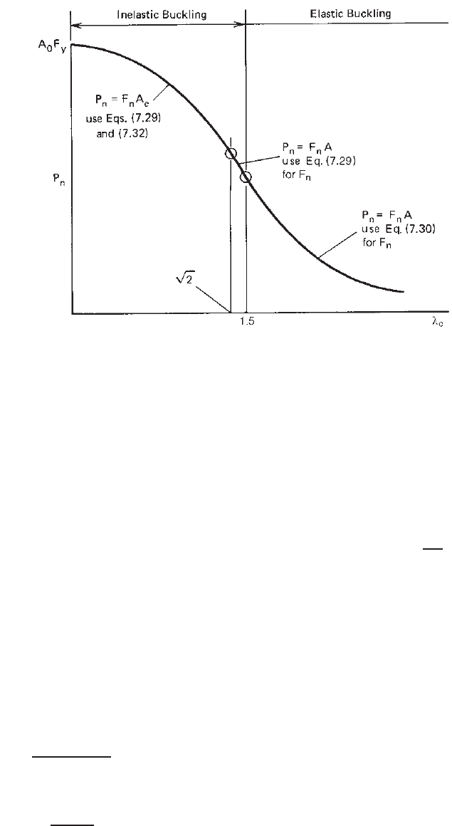
Equations (7.28)–(7.34) can be summarized in Fig. 7.9. It
can be seen that Eq. (7.32) gives A
e
= A
o
when λ
c
= 0
and A
e
= A when λ
c
=
√
2. The latter is due to the fact that
for long columns the stresses at which the column buckles
are so low that they will not cause local buckling before
primary buckling has taken place.
Consequently, for the design of axially loaded closed
cylindrical tubular members, the allowable axial load P
a
for the ASD method is determined by Eq. (7.35):
P
a
=
P
n
c
(7.35)
where
c
= 1.80 is the safety factor for axial compression.
For the LRFD and LSD methods, the design axial strength
is φ
c
P
n
,inwhichφ
c
equals 0.85 for LRFD and 0.80 for
LSD.
7.5.3 Bending Strength
In Section 7.4.2, it was pointed out that for closed cylin-
drical tubular members the elastic local buckling stress for
bending is higher than the elastic local buckling stress for
axial compression. In addition, it has been recognized that
258 7 CLOSED CYLINDRICAL TUBULAR MEMBERS
Figure 7.9 Nominal compressive load of cylindrical tubular members.
for thick closed cylindrical members subjected to bending
the initiation of yielding does not represent the failure
condition, as is generally assumed for axial loading. For
relatively compact members with D/t ≤ 0.0714E/F
y
,the
flexural strength can reach the plastic moment capacity,
which is at least 1.25 times the moment at first yielding.
As far as the local buckling is concerned, the conditions
for inelastic buckling are not as severe as the case of axial
compression due to the effect of the stress gradient. Based
on the results of previous studies, the following design
provisions for determining the nominal flexural strength
are included in Section C3.1.3 of the 2007 edition of the
North American specification for closed cylindrical tubular
members having D/t ≤ 0.441E/F
y
1.314, 1.333, 1.345
:
M
n
= F
c
S
f
(7.36)
1. For D/t ≤ 0.0714E/F
y
,
F
c
= 1.25F
y
(7.37)
2. For 0.0714E/F
y
<D/t≤=0.318E/F
y
,
F
c
=
0.970 +
0.020
E/F
y
D/t
F
y
(7.38)
3. For 0.318E/F
y
<D/t≤ 0.441E/F
y
:
F
c
=
0.328E
D/t
(7.39)
where M
n
= nominal flexural strength
D = outside diameter of cylindrical tube
t = wall thickness
F
c
= critical flexural bending stress
S
f
= elastic section modulus of full, unreduced
cross section relative to extreme compression
fiber
The allowable flexural strength M
a
for the ASD method
is determined by using Eq. (7.40):
M
a
=
M
n
b
(7.40)
where
b
= 1.67 is the safety factor for bending. For the
LRFD and LSD methods, the design flexural strength is
φ
b
M
n
,inwhichφ
b
equals 0.95 for LRFD a nd 0.90 for
LSD.
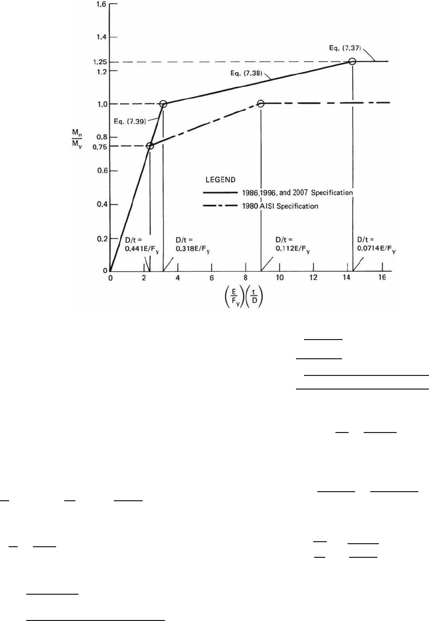
The nominal flexural strengths based on the critical flex-
ural buckling stresses from Eqs. (7.37)–(7.39) are shown
graphically in Fig. 7.10. As compared with the 1980 edition
of the AISI specification, it can be shown that the increases
of the nominal moment range from about 13 to 25%
according to the value of (E/F
y
)(t/D).
7.5.4 Combined Bending and Compression
The interaction formulas presented in Chapter 6 can also
be used for the design of beam–columns using closed
cylindrical tubular members. The nominal axial strength
and nominal flexural strength can be obtained from Sections
7.5.2 and 7.5.3, respectively.
DESIGN EXAMPLES 259
Figure 7.10 Nominal flexural strength of cylindrical tubular members.
7.6 DESIGN EXAMPLES
Example 7.1 Use the ASD and LRFD methods to deter-
mine the a vailable axial strength for the closed cylindrical
tube having 10 in. outside diameter to be used as an axially
loaded simply supported column. Assume that the effective
column length is 15 ft, the yield stress of steel is 33 ksi,
and the thickness of the tube is 0.105 in.
SOLUTION
A. ASD Method.
Using the North American design criteria, the limiting D/t
ratio is
D
t
lim
= 0.441
E
F
y
= 0.441
29,500
33
= 394.23
The actual D/t ratio is
D
t
=
10
0.105
= 95.24 < 394.23 OK
1. Sectional Properties of Full Section
A =
π(D
2
o
− D
2
i
)
4
=
π[(10.0)
2
− (10.0 − 2 × 0.105)
2
]
4
= 3.264 in.
2
r =
D
2
o
+ D
2
i
4
=
(10.0)
2
+ (10.0 − 2 × 0.105)
2
4
= 3.500 in.
2. Nominal Axial Strength P
n
a.
KL
r
=
15 × 12
3.50
= 51.43
According to Eq. (5.56), the elastic flexural buck-
ling stress is
F
e
=
π
2
E
(KL/r)
2
=
π
2
(29,500)
(51.43)
2
= 110.08 ksi
b. Based on Eq. (7.31),
λ
c
=
F
y
F
e
=
33
110.08
= 0.548 < 1.5
F
n
= (0.658
λ
2
c
)F
y
= (0.658
0.548
2
)(33) = 29.10 ksi
c. Based on Eqs. (7.32), (7.33), and (7.34),
A
e
= A
o
+ R(A − A
o
)

260 7 CLOSED CYLINDRICAL TUBULAR MEMBERS
where
R =
F
y
2F
e
=
33
2 × 110.08
= 0.150 < 1.0OK
A
o
=
0.037
(D/t)(F
y
/E)
+ 0.667
A
=
0.037
(95.24)(33/29,500)
+ 0.667
(3.264)
= 3.311 in.
2
Because 3.311 > A = 3.264 in.
2
,useA
o
=
3.264 in.
2
Therefore,
A
e
= 3.264 + (0.150)(3.264 −3.264)
= 3.264 in.
2
From Eq. (7.28), the nominal axial load is
P
n
= F
n
A
e
= (29.10)(3.264) = 94.98 kips
3. Allowable Axial Load P
a
. From Eq. (7.35), the allow-
able axial load is
P
a
=
P
n
c
=
94.98
1.80
= 52.77 kips
B. LRFD Method.
For the LRFD method, the design axial strength is
φ
c
P
n
= 0.85(94.98) = 80.73 kips
Example 7.2 AlldataarethesameasthoseofExample
7.1, except that the thickness of the tube is 0.06 in.
SOLUTION
A. ASD Method.
Use the same procedure employed in Example 7.1:
D
t
lim
= 0.441
E
F
y
= 394.23
The actual D/t ratio is
D
t
=
10
0.06
= 166.67 < 394.23 OK
1. Sectional Properties of Full Section
A =
π[(10.0)
2
− (10.0 − 2 × 0.06)
2
]
4
= 1.874 in.
2
r =
(10.0)
2
+ (10.0 − 2 × 0.06)
2
4
= 3.51 in.
2. Nominal Axial Strength P
n
a.
KL
r
=
15 × 12
3.51
= 51.28
F
e
=
π
2
E
(KL/r)
2
=
π
2
(29,500)
(51.28)
2
= 110.72 ksi
b. Based on Eq. (7.31),
λ
c
=
F
y
F
e
=
33
110.72
= 0.546 < 1.5
F
n
= (0.658
λ
2
c
)F
y
= (0.658
0.546
2
)(33)
= 29.13 ksi
c. Based on Eqs. (7.32), (7.33), and (7.34),
A
e
= A
o
+ R(A − A
o
)
where
R = F
y
/(2F
e
) = 33/(2 × 110.72)
= 0.149 < 1.0OK
A
o
=
0.037
(166.67)(33/29,500)
+ 0.667
(1.874)
= 1.622 in.
2
Since A
o
<A= 1.874 in.
2
,useA
o
= 1.622 in.
2
A
e
= 1.622 + (0.149)(1.874 − 1.622)
= 1.660 in.
2
The nominal axial strength is
P
n
= F
n
A
e
= (29.13)(1.660)
= 48.36 kips
3. Allowable Axial Load P
a
. From Eq. (7.35), the allow-
able axial load is
P
a
=
P
n
c
=
48.36
1.80
= 26.87 kips
B. LRFD Method.
For the LRFD method, the design axial strength is
φ
c
P
n
= 0.85(48.36) = 41.11 kips
Example 7.3 Use the ASD and LRFD methods to deter-
mine the available flexural strength of the closed cylindrical
tubes used in Examples 7.1 and 7.2 if these tubes are to be
used as flexural members.

DESIGN EXAMPLES 261
SOLUTION
A. ASD Method
1. Use the data given in Example 7.1,
F
y
= 33 ksi
D
o
= 10 in.
t = 0.105 in.
D
t
= 95.24 <
0.441E
F
y
OK
a. Section Modulus of Full Section. The section
modulus of the 10-in. tube having a wall thickness
of 0.105 in. is
S
f
=
π(D
4
o
− D
4
i
)
32D
o
= 0.098175
D
4
o
− D
4
i
D
o
= 0.098175
(10.0)
4
− (9.79)
4
10.0
= 7.99 in.
3
b. Nominal Flexural Strength M
n
. From Eq. (7.36),
M
n
= F
c
S
f
0.0714E
F
y
=
0.0714
(
29,500
)
33
= 63.83
0.318E
F
y
=
0.318
(
29,500
)
33
= 284.27
Since 0.0714E/F
y
<(D/t= 95.24)<0.318E/
F
y
, according to Eq. (7.38), the nominal flexural
strength is
M
n
=
0.970 + 0.020
(E/F
y
)
D/t
F
y
S
f
=
0.970 + 0.020
(29,500/33)
95.24
(33)(7.99)
= 305.26 in.-kips
c. Allowable Flexural Strength M
a
. Based on Eq.
(7.40), the allowable flexural strength is
M
a
=
M
n
b
=
305.26
1.67
= 182.79 in.-kips
2. Use the data given in Example 7.2,
F
y
= 33 ksi
D
o
= 10 in.
t = 0.06 in.
D
t
= 166.67 <
0.441E
F
y
OK
a. Section m odulus of Full Section. The section
modulus of the 10-in. tube having a wall thickness
of 0.06 in. is
S
f
= 0.098175
(10.0)
4
− (9.88)
4
10.0
= 4.628 in.
3
b. Nominal Flexural Strength M
n
. From Eq. (7.36),
M
n
= F
c
S
f
Since 0.0714E/F
y
<D/t<0.318E/F
y
, the nom-
inal flexural strength is
M
n
=
0.970 + 0.020
(29,500/33)
166.67
(33)(4.628)
= 164.53 in.-kips
c. Allowable Flexural Strength M
a
. The allowable
flexural strength is
M
a
=
M
n
b
=
164.53
1.67
= 98.52 in.-kips.
B. LRFD Method
Using the LRFD method, the design flexural strengths for
the closed cylindrical tubes used in Examples 7.1 and 7.2
can be computed as follows:
1. For the closed cylindrical tube used in Example 7.1,
the nominal flexural strength computed in item A
above is
M
n
= 305.26 in.-kips
The design flexural strength is
φ
b
M
n
= 0.95(305.26) = 290.00 in.-kips
2. For the closed cylindrical tube used in Example 7.2,
the nominal flexural strength computed in Item A
above is
M
n
= 164.53 in.-kips
The design flexural strength is
φ
b
M
n
= 0.95(164.53) = 156.30 in.-kips
CHAPTER 8
Connections
8.1 GENERAL REMARKS
In Chapters 4–7 the design of individual structural
members, such as beams, columns, tension members, and
cylindrical tubular members, to be used in cold-formed
steel construction has been discussed. It is often found
that such structural members are fabricated from steel
sheets or structural components by using various types
of connections. In addition, connections are required for
joining individual members in overall structures.
In this chapter the types of connections generally used
in cold-formed steel structures, the design criteria for
various types of connections, the requirements to fabricate
I- or box-shaped beams and columns by connecting two
channels, and the spacing of connections in compression
elements are discussed.
For connection design tables and example problems,
reference should be made to Part IV of the Design Manual.
As a general rule of the AISI North American Spec-
ification, all connections should be designed to transmit
the maximum design force in the connected member with
proper regard for eccentricity.
8.2 TYPES OF CONNECTORS
Welds, bolts, cold rivets, screws, power-driven pins,
and other special devices such as metal stitching and
adhesives are generally used in cold-formed steel con-
nections.
1.159,1.161,8.1–8.10,8.63–8.65, 8.95, 8.102, 8.103
The AISI
North American Specification contains provisions in
Section E for welded, bolted, and screw connections,
which are most commonly used.
In the design of connections using cold rivets and power-
actuated fasteners, the AISI provisions for bolted connec-
tions may be used as a general guide, except that the shear
strength of the fastener may be quite different from that
of bolts and different failure modes such as pullout and
inclination of fasteners should also be considered. Addi-
tional information on the strength of connections should
be obtained from manufacturers or from tests. Section 8.6
gives a brief discussion on the application of cold rivets,
power-actuated fasteners, and press-joints.
8.3 WELDED CONNECTIONS
Welds used for building construction may be classified as
arc welds and resistance welds.
Arc welding is a group of processes in which metals
were welded together by using weld metal at the surfaces
to be joined without the application of mechanical pressure
or blows.
Resistance welding is a group of welding processes
where coalescence is produced by the heat obtained from
resistance to an electric current through the work parts held
together under pressure by electrodes.
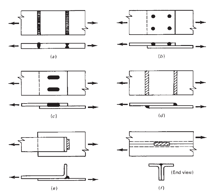
8.3.1 Arc We lds
Arc welds are often used for erection, connecting cold-
formed steel members to each other, or connecting cold-
formed steel members to hot-rolled framing members.
Several types of arc welds generally used in cold-formed
steel construction are:
1. Groove welds
2. Arc spot welds (puddle welds)
3. Arc seam welds
4. Fillet welds
5. Flare groove welds
Figure 8.1 shows different types of arc welds.
Arc spot welds used for thin sheets are similar to plug
welds used for relatively thicker plates. The difference
between plug welds and arc spot welds is that the former
are made with prepunched holes, but for the latter no
prepunched holes are required. A hole is burned in the top
sheet and then filled with weld metal to fuse it to the bottom
sheet or structural members. Similarly, arc seam welds are
the same as slot welds, except that no prepunched holes are
required for the former.
The American Welding Society (AWS) has established
certain welding symbols. Figure 8.2 shows the basic
symbols and the standard locations of the elements of a
welding symbol used in cold-formed steel structures.
8.11
With regard to the research work on arc welds, the earlier
AISI design provisions for fillet welds and arc spot welds
were based on the results of 151 tests conducted in the
1950s at Cornell University.
1.161
In the 1970s a total of
263
264 8 CONNECTIONS
Figure 8.1 Types of arc welds: (a) groove welds in butt joints; (b) arc spot welds; (c) arc seam
welds; (d)filletwelds;(e) flare bevel groove weld; (f ) flare V-groove weld.
342 additional tests on fillet, flare bevel, arc spot, and
arc seam welded connections were carried out at Cornell
University under the sponsorship of the AISI.
8.12,8.13
The
structural behavior of the most common types of arc welds
used for sheet steel has been studied in detail. Based on
the research findings at Cornell University summarized by
Pekoz and McGuire
8.12,8.13
and a study by Blodgett of
the Lincoln Electric Company,
8.14
the first edition of the
“Specification for Welding Sheet Steel in Structures” was
developed by the Subcommittee on Sheet Steel of the AWS
Structural Welding Committee in 1978.
8.15
The second
edition of this document, entitled “Structural Welding
Code—Sheet Steel,” was issued by the AWS in 1989.
8.16
The current edition of Structural Welding Code—Sheet Steel
was published in 2008.
8.96
Based on the same data, in
1980, the AISI design provisions for arc welds were revised
extensively to reflect the research results. The same design
provisions were used in the 1986 AISI specification with
additional design formulas included in the 1989 Addendum
for tensile load of arc spot welds. Minor revisions were
made in 1996 with new figures added for the design of flare
bevel groove welds. In the supplement to the 1996 AISI
Specification, design equations are used to replace tabular
values for determining the nominal shear strength of resis-
tance welds. In 2007 new design equations were provided
in the AISI North American Specification for tension on
arc spot welds and for the shear strength of sheet-to-sheet
arc spot welds.
The following sections summarize the research findings
on the structural strengths of various types of arc welds.
As discussed in Refs. 8.12 and 8.13, the thickness of steel
sheets used in the Cornell test program ranged from 0.019
to 0.138 in. (0.48 to 3.5 mm). The yield points of materials
varied from 33 to 82 ksi (228 to 565 MPa). All specimens
were welded with E6010 electrodes.
8.3.1.1 Arc Spot Welds Based on the results of 126 tests
on arc spot welds, it was found that the limit states of arc
spot welds include shear failure of welds in the fused area,
tearing of the sheet along the contour of the weld with
the tear spreading across the sheet at the leading edge of
the weld, sheet tearing combined with buckling near the