Yu W., LaBoube R.A. Cold-Formed Steel Design
Подождите немного. Документ загружается.

STRUCTURAL BEHAVIOR OF COMPRESSION ELEMENTS AND DESIGN CRITERIA 65
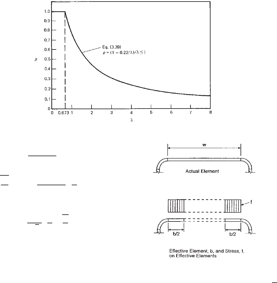
Figure 3.18 Reduction factor ρ vs. slenderness factor λ.
and
ρ =
1 − 0.22/λ
λ
≤ 1 (3.43)
where the plate slenderness factor λ is given as
λ =
f
f
cr
f
cr
=
kπ
2
E
12(1 − μ
2
)
t
w
2
The above equation for the plate slenderness factor can
be simplified to Eq. (3.44) by using μ = 0.3:
λ =
1.052
√
k
w
t
f
E
(3.44)
where k = plate buckling coefficient
= 4.0 for stiffened elements supported by a web
on each longitudinal edge as shown in
Fig. 3.19. Values for different types of
elements are given in the applicable sections
of the North American Specification.
w = width of stiffened compression element
t = thickness of compression element
E = modulus of elasticity
f = maximum compressive edge stress in element
without considering safety factor
Since Eq. (3.44) is a simpler equation than the design proce-
dure prescribed in the North American Specification, this
equation is used in this book for computing the slenderness
factor λ.
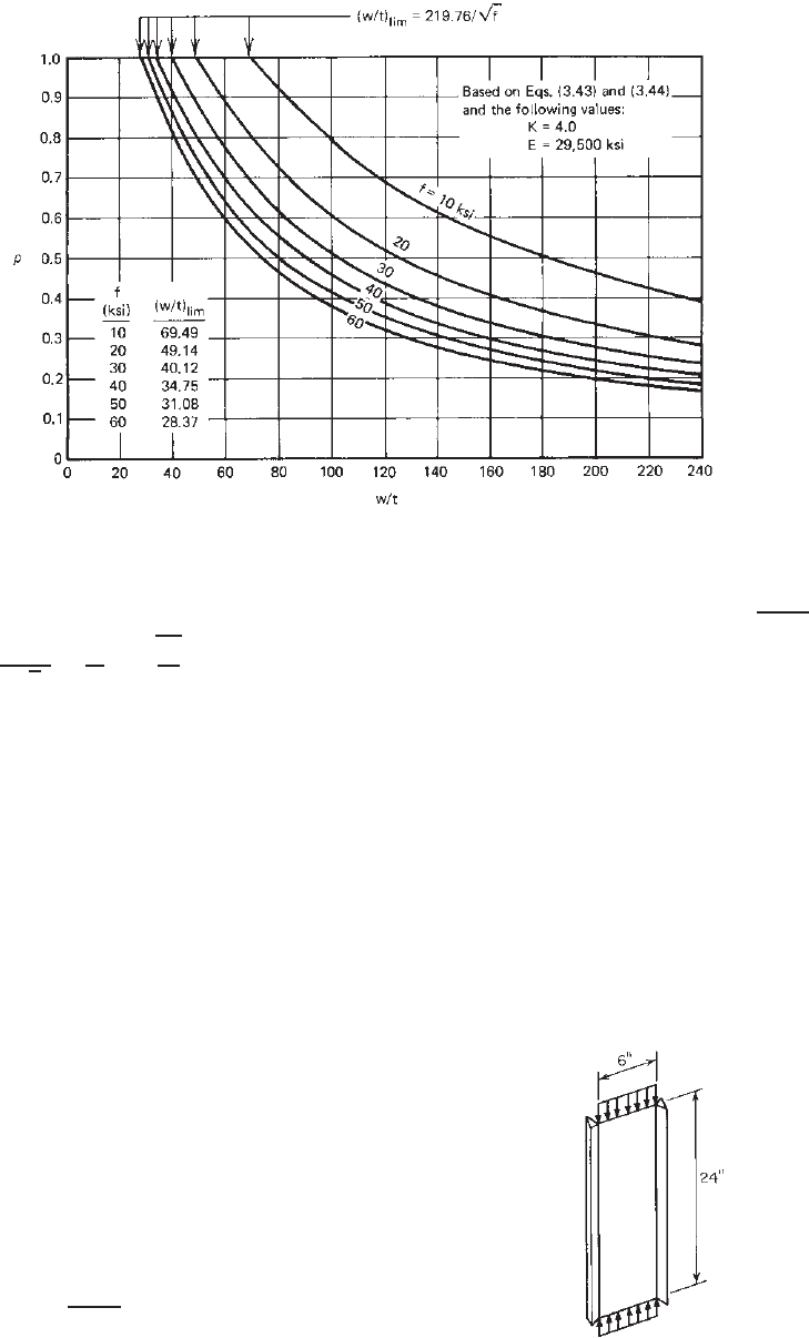
Figure 3.20 is a graphic presentation of Eqs. (3.43) and
(3.44) plotted for k = 4.0 and E = 29,500 ksi. It can be used
for determination of the effective design width of stiffened
elements with a given w/t ratio and compressive stress.
Figure 3.19 Uniformly compressed stiffened elements.
1.345
Note that the limiting w/t ratio, (w/t)
lim
, is 219.76/
√
f.
When w/t ≤ (w/t)
lim
, no reduction of the flat width is
required for stiffened e lements supported by a web on each
longitudinal edge.
(b) Serviceability Determination
b
d
=
w for λ ≤ 0.673 (3.45)
ρw for λ ≥ 0.673 (3.46)
where b
d
= effective design width of compression
element for serviceability determination
w = flat width of compression element
ρ = reduction factor determined from Eq. (3.43)
66 3 STRENGTH OF THIN ELEMENTS AND DESIGN CRITERIA
Figure 3.20 Reduction factor ρ for stiffened compression elements.
The plate slenderness factor λ is determined as
λ =
1.052
√
k
w
t
f
d
E
(3.47)
where f
d
is the computed compressive stress in the element
being considered and k , t,andE are the same as that
defined above for strength determination.
The above method [Eqs. (3.45)–(3.47)] can be used to
obtain a conservative effective width b
d
for serviceability
determination. It is included in Section B2.1(b) of the North
American Specification as Procedure I. Figure 3.20 can also
be used for the determination of the effective width for
serviceability using this procedure.
For stiffened compression elements supported by a web
on each longitudinal edge, a study conducted by Weng and
Pekoz indicated that Eqs. (3.48)–(3.51) can yield a more
accurate estimate of the effective width b
d
for service-
ability. The following equations are included in the North
American Specification as Procedure II:
ρ =
⎧
⎪
⎪
⎪
⎪
⎪
⎪
⎪
⎪
⎨
⎪
⎪
⎪
⎪
⎪
⎪
⎪
⎪
⎩
1forλ ≤ 0.673 (3.48)
(1.358 − 0.461/λ)/λ ≤ 1
for 0.673 <λ<λ
c
(3.49)
(0.41 + 0.59
F
y
/f
d
− 0.22/λ)/λ ≤ 1
for λ ≥ λ
c
(3.50)
where
λ
c
= 0.256 + 0.328(w/t)
F
y
/E (3.51)
and λ is defined by Eq. (3.47).
Example 3.1 For the given thin plate supported along
both longitudinal edges as shown in Fig. 3.21, determine
the following items using the U.S. customary unit:
1. Critical buckling stress
2. Critical buckling load
3. Ulitmate load.
Given:
t = 0.06 in. E = 29.5 × 10
3
ksi F
y
= 50 ksi
μ = 0.3
Figure 3.21 Example 3.1.
STRUCTURAL BEHAVIOR OF COMPRESSION ELEMENTS AND DESIGN CRITERIA 67
SOLUTION
1. Critical Buckling Stress [Eq. (3.16)]. Since the aspect
ratio is 4, use k = 4.0 as follows:
f
cr
=
kπ
2
E
12(1 − μ
2
)(w/t)
2
=
4(3.1416)
2
× (29.5 × 10
3
)
12(1 − 0.3
2
)(6/0.06)
2
= 10.665 ksi
2. Critical Buckling Load. P
cr
= Af
cr
= 6(0.06) ×
(10.665) = 3.839 kips.
3. Ultimate Load. The ultimate load can be computed
from the effective width b determined by Eq. (3.41)
or Eq. (3.42). From Eq. (3.44),
λ =
1.052
√
k
w
t
f
E
=
1.052
√
4
6.0
0.06
50
29,500
= 2.166
Since λ>0.673, b = ρw,where
ρ =
1 − 0.22/λ
λ
=
1 − 0.22/2.166
2.166
= 0.415
Therefore, the effective design width and the ultimate
load are c omputed as follows:
b = ρw = 0.415(6.0) = 2.49 in.
P
ult
= A
eff
F
y
= 2.49(0.06)(50) = 7.47 kips
It is seen that here the ultimate load of 7.47 kips
is almost twice the critical buckling load of
3.839 kips.
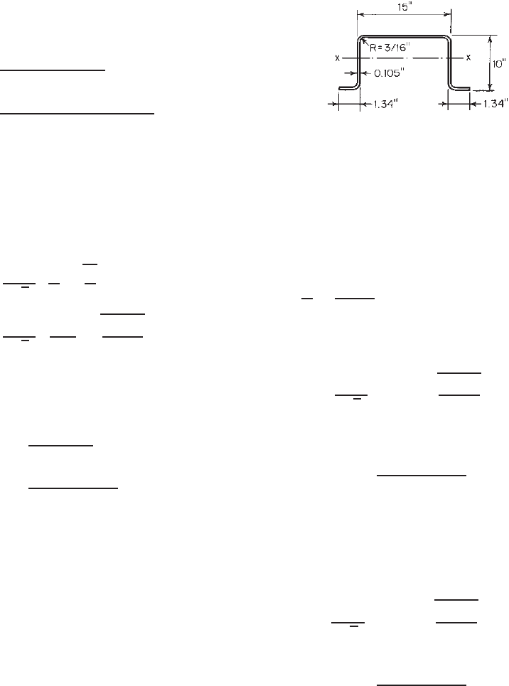
Example 3.2 Compute the effective design width of the
compression flange of the beam shown in Fig. 3.22 using
the U.S. customary unit.
(a) For strength determination—assume that the compres-
sive stress in the flange without considering the safety
factor is 25 ksi.
(b) For serviceability determination—assume that the com-
pressive stress in the flange under the service or allow-
able load is 15 ksi.
Figure 3.22 Example 3.2.
SOLUTION
1. Strength Determination. As the first step, compute λ
using Eq. (3.44) with the following values:
k = 4.0
w = 15.00 − 2(R + t)
= 15.00 − 2(0.1875 + 0.105) = 14.415 in.
w
t
=
14.415
0.105
= 137.286
f = 25 ksi
E = 29,500 ksi
λ =
1.052
√
4
(137.286)
25
29,500
= 2.102
Since λ>0.673, compute the reduction factor ρ
according to Eq. (3.43):
ρ =
1 − 0.22/2.102
2.102
= 0.426
Therefore, the effective design width for strength
determination is
b = ρw = (0.426)(14.415) = 6.14 in.
2. Serviceability Determination. By using Eq. (3.47) and
f
d
= 15 ksi,
λ =
1.052
√
4
(137.286)
15
29,500
= 1.628
Since λ>0.673,
ρ =
1 − 0.22/1.628
1.628
= 0.531
Therefore, the effective design width for serviceability
determination is
b
d
= ρw = (0.531)(14.415) = 7.654 in.
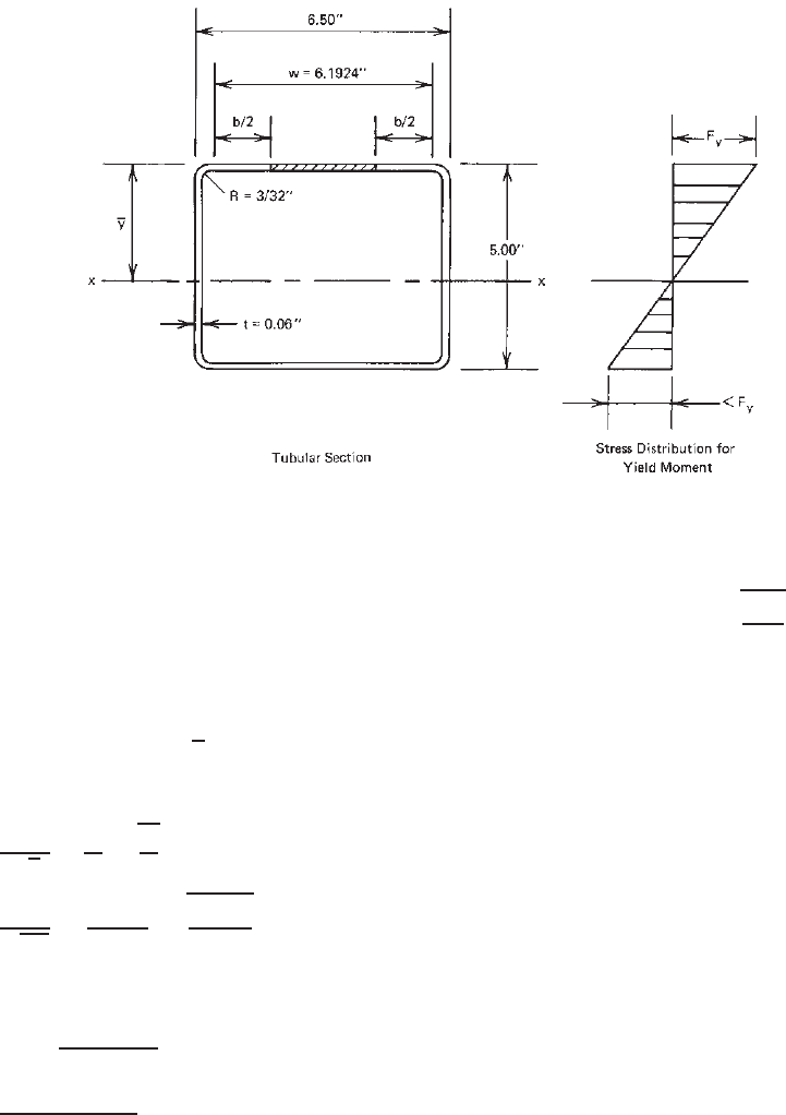
Example 3.3 Calculate the effective width of the
compression flange of the box section (Fig. 3.23) to be
used as a beam bending about the x axis. Use F
y
= 33 ksi.
Assume that the beam webs are fully effective a nd that the
bending moment is based on initiation of yielding. Use the
U.S. customary unit.
68 3 STRENGTH OF THIN ELEMENTS AND DESIGN CRITERIA
Figure 3.23 Example 3.3.
SOLUTION. Because the compression flange of the given
section is a uniformly compressed stiffened element, which
is supported by a web on each longitudinal edge, the
effective width of the flange for strength determination can
be computed by using Eqs. (3.41)–(3.44) with k = 4.0.
Assume that the bending strength of the section is based
on initiation of yielding (procedure I of Section C3.1.1 of
the North American Specification),
y ≥ 2.50 in. Therefore,
the slenderness factor λ for f = F
y
can be computed from
Eq. (3.44), that is,
λ =
1.052
√
k
w
t
f
E
=
1.052
√
4.0
6.1924
0.06
33
29,500
= 1.816
Since λ>0.673, use Eqs. (3.42) and (3.43) to compute the
effective width b as follows:
b = ρw =
1 − 0.22/λ
λ
w
=
1 − 0.22/1.816
1.816
(6.1924) = 3.00 in.
The above discussion on the structural design of stiffened
compression elements is based on the North American
Specification.
1.345
In other countries the design equations
and methods for determining the effective design width
may be different as compared with the AISI formulas.
For example, in the Japanese Standard
1.186
the effective
design width is independent of the flat-width ratio w/t.
This approach is similar to Eq. (3.52), which was derived
by Lind et al.
3.20,3.21
on the basis of their statistical analysis
of the available experimental results:
b = 1.64t
E
f
max
(3.52)
Equation (3.52) was used in the Canadian Standard
during the period from 1974 through 1984.
In the British Standard the effective design width is
determined by using the w/t ratio and the design equations
given in Ref. 1.194. For the design of steel decks and
panels, European recommendations
1.209, 1.328
have adopted
Winter’s formula as given in Eqs. (3.38)–(3.40). In Refs.
1.183, 1.184, and 3.22 the French recommendations give
an effective design width similar to that permitted by the
North American Specification.
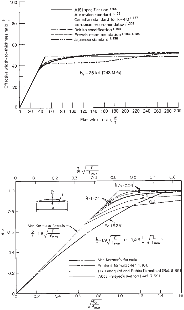
The effective design widths of the stiffened compres-
sion element as determined by several design specifica-
tions have been compared in Fig. 3.24. Reference 1.147
included comparisons of different specifications being used
in Australia, China, Eastern Europe, Japan, North America,
and Western Europe. Additional information on effective
design width can be found in Refs. 3.23–3.37.
Influence of Initial Imperfection on Effective Design
Width. The load-carrying capacity of stiffened compres-
sion elements is affected by the initial imperfection of the
plate. The larger the initial imperfection, the smaller the
capacity.
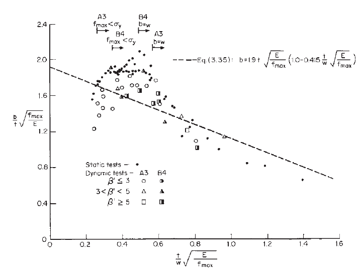
The influence of initial imperfection on the effective
design width has previously been studied by Hu et al.
3.38
and by Abdel-Sayed.
3.39
Figure 3.25 shows the theoretical
ratio of effective width to actual width, b/w, affected
by various values of initial imperfections. Imperfect
STRUCTURAL BEHAVIOR OF COMPRESSION ELEMENTS AND DESIGN CRITERIA 69
Figure 3.24 Comparison of effective design widths for load determination by using various design
specifications.
Figure 3.25 Effect of initial imperfection on effective design width.
70 3 STRENGTH OF THIN ELEMENTS AND DESIGN CRITERIA
plates have also been studied extensively by Dawson and
Walker,
3.40
Sherbourne and Korol,
3.41
Hancock,
3.42
and
Maquoi and Rondal.
3.43
Influence of Impact Loading on Effective Design Width.
Previous discussion on effective width was concerned with
the compression elements subjected to static loading. This
type of loading condition is primarily applicable to the
design of cold-formed steel members used in building
construction.
As indicated in Section 1.1, cold-formed steel members
are also used in car bodies, railway coaches, various types
of equipment, storage racks, highway products, and bridge
construction, all of which are subjected to dynamic loads.
Since members subjected to dynamic loads behave differ-
ently than those subjected to static loads, the question arises
as to whether direct application of the AISI design criteria
based on static loading is appropriate. In order to develop
the necessary information on this topic, research work has
been conducted by Culver and his collaborators at Carnegie-
Mellon University to study analytically and experimen-
tally the behavior of thin compression elements, beams,
and columns subjected to dynamic or time-dependent
loading.
3.44–3.49
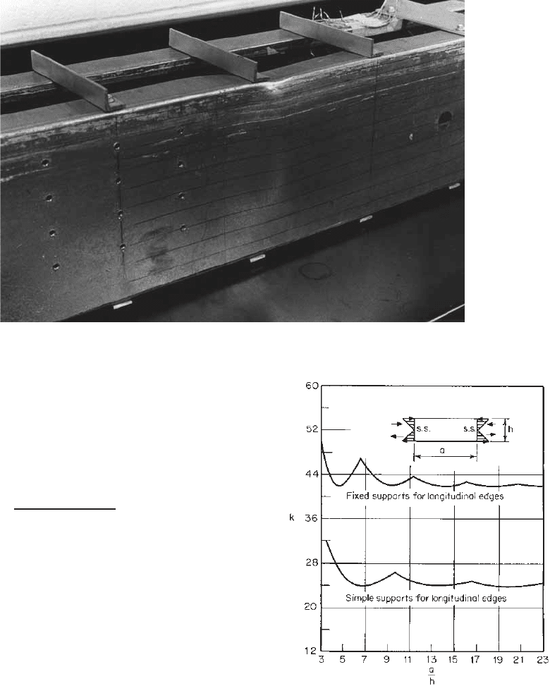
It was found that the effective design width
formula [Eq. (3.35)] satisfies both the static and the dynamic
results to the same degree of accuracy.
3.44,3.46
Figure 3.26
shows the correlation between the test data and Eq. (3.35).
In this figure β
is the ratio of the time duration of the
stress pulse to the fundamental period of the compression
flange treated as a simply supported plate. This subject has
also been studied at the University of Missouri-Rolla under
a project on automotive structural components.
3.50,2.67–2.71
In Ref. 2.103, Rhodes and Macdonald reported channel
section beams under static and impact loading.
3.5.1.2 Beam Webs and Stiffened Elements with Stress
Gradient When a flexural member is subjected to
bending moment, the compression portion of the web may
buckle due to the compressive stress caused by bending.
Figure 3.27 shows a typical pattern of bending failure of
beam webs.
Prior to 1986, the design of beam webs in the United
States was based on the full web depth and the allowable
bending stress specified in the 1980 and earlier editions of
the AISI Specification. In order to unify the design methods
for webs and compression flanges, the “effective web depth
approach” was adopted in the 1986 edition of the AISI
Specification.
1.4
The same design approach was used in the
1996 AISI Specification
1.314
and is retained in the North
American Specification.
1.336,1.345
Figure 3.26 Correlation between effective design width formula and test data.
3.46
STRUCTURAL BEHAVIOR OF COMPRESSION ELEMENTS AND DESIGN CRITERIA 71
Figure 3.27 Typical bending failure pattern for channel sections.
3.60
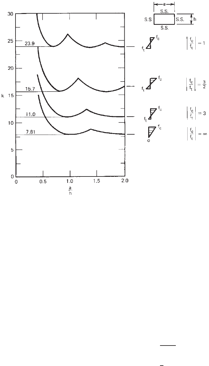
Web Buckling due to Bending Stress. The buckling
of disjointed flat rectangular plates under bending with
or without longitudinal loads has been investigated by
Timoshenko, Schuette, McCulloch, Johnson, and Noel.
3.1,3.2
The theoretical critical buckling stress for a flat rectangular
plate under pure bending can be determined by Eq. (3.53):
f
cr
=
kπ
2
E
12(1 − μ
2
)(h/t)
2
(3.53)
where h is the depth of the web and k is the buckling coef-
ficient. For long plates the value of k was found to be 23.9
for simple supports and 41.8 for fixed supports as listed in
Table 3.4. The relationships between the buckling coeffi-
cient and the aspect ratio a/h are shown in Fig. 3.28. When
a s imply supported plate is subjected to a compressive
bending stress higher than the tensile bending stress, the
buckling coefficient k is reduced according to the bending
stress ratio f
c
/f
t
asshowninFig.3.29.
3.7
In practice the bending strength of a beam web not only
is affected by the web slenderness ratio h/t, the aspect ratio
a/h, and the bending stress ratio f
c
/f
t
but also depends
on the mechanical properties of material (E , F
y
,andμ)
and the interaction between flange and web components. In
addition, the buckling coefficient k for the web is influenced
by the actual edge restraint provided by the beam flange.
Because the derivation of an exact analytical solution for the
stability and the postbuckling strength of plate assemblies is
extremely cumbersome, the AISI design criteria have been
based on the results of tests.
Figure 3.28 Bending buckling coefficients of plates vs. aspect
ratio, a/h.
3.1
Postbuckling Strength and Effective Depth of Webs.
In the past, several design formulas for computing the
effective web depth have been developed by Bergfelt,
Thomasson, Kallsner, Hoglund, DeWolf, Gladding,
LaBoube, and Yu
3.51−3.61
to account for the actual buck-
ling strength and the postbuckling behavior of beam
webs. The effective web depth approach has been used in
several specifications.
3.62,3.63
In 1986, Cohen and Pekoz
3.64
72 3 STRENGTH OF THIN ELEMENTS AND DESIGN CRITERIA
Figure 3.29 Buckling coefficient k for simply supported plates subjected to nonuniform longitu-
dinal bending stress.
3.7
(Reproduced with permission from Chatto & Windus, London.)
evaluated the test results reported by LaBoube and
Yu,
3.59–3.61
Cohen and Pekoz,
3.64
Kallsner,
3.54
Johnson,
3.65
He,
3.66
and van Neste
3.67
and developed the needed design
formulas for webs connected to stiffened, unstiffened, and
partially stiffened compression flanges. Some statistical
data on the correlation are given in Ref. 3.17.
Consequently, design equations were included in
Section B2.3 of the 1986 edition of the AISI Specification
for computing the effective width of webs and stiffened
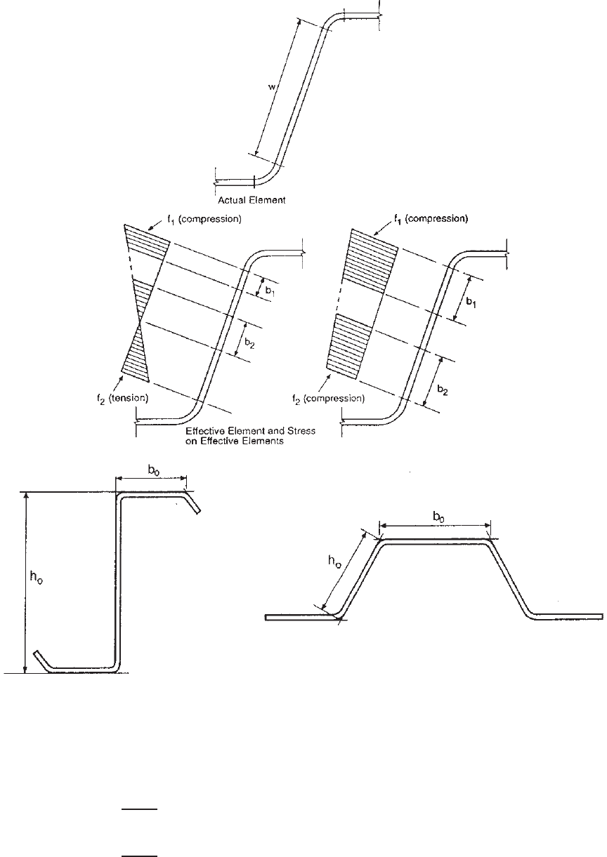
elements with a stress gradient as shown in Fig. 3.30. The
same equations were used in the 1996 edition of the AISI
Specification.
Because the AISI design equations for computing the
effective width of webs implicitly assumed that the beam
flange provided beneficial restraint to the web, the test
data on flexural tests of C - and Z-sections summarized by
Schafer and Pekoz
3.168
indicated that the AISI equations
can be unconservative if the overall web depth (h
0
)to
overall flange width (b
0
) ratio exceeds 4. In 2001, due
to the lack of a comprehensive method for handling web
and flange interaction, the North American Specification
adopted the following two-part approach in Section B.2.3
for computing the effective width of beam webs and
other stiffened elements under a stress gradient. The same
design equations are retained in the 2007 edition of the
Specification:
(a) Strength Determination
(i) For webs under a stress gradient (f
1
in compression
and f
2
in tension as shown in Fig. 3.30a):
k = 4 + 2(1 + ψ)
3
+ 2(1 + ψ) (3.54)
For h
0
/b
0
≤ 4
b
1
=
b
e
3 + ψ
(3.55a)
b
2
=
1
2
b
e
when ψ>0.236 (3.55b)
b
2
= b
e
− b
1
when ψ ≤ 0.236 (3.55c)
STRUCTURAL BEHAVIOR OF COMPRESSION ELEMENTS AND DESIGN CRITERIA 73
(a) (b)
(c)
Figure 3.30 (a, b) Stiffened elements with stress gradient and webs.
1.345
(c) Out-to-out dimen-
sions of webs and stiffened elements under stress gradient.
1.345
For h
0
/b
0
> 4
b
1
=
b
e
3 + ψ
(3.56a)
b
2
=
b
e
1 + ψ
− b
1
(3.56b)
In addition, b
1
+ b
2
shall not exceed the compression
portion of the web calculated on the basis of the
effective section.
(ii) For other stiffened elements under a stress gradient
(f
1
and f
2
in compression as shown in Fig. 3.30b)
k = 4 + 2(1 − ψ)
3
+ 2(1 − ψ) (3.57)
74 3 STRENGTH OF THIN ELEMENTS AND DESIGN CRITERIA
b
1
=
b
e
3 − ψ
(3.58a)
b
2
= b
e
− b
1
(3.58b)
In the above expressions,
b
1
= effective width as shown in Fig. 3.30
b
2
= effective width as shown in Fig. 3.30
b
e
= effective width b determined in accordance
with Eq. (3.41) through Eq. (3.44) with
f
1
substituted for f and k determined from
Eq. (3.54) or (3.57)
b
0
= out-to-out width of compression flange as
showninFig.3.30c
f
1
,f
2
= stresses shown in Fig. 3.30 calculated on
basis of effective section, where f
1
and f
2
are both compression, f
1
≥ f
2
h
0
= out-to-out depth of web as shown in
Fig. 3.30c
k = plate buckling coefficient
ψ =|f
2
/f
1
| (absolute value)
(b) Serviceability Determination. The effective widths used
in determining serviceability shall be calculated in
accordance with Eqs. (3.54)–(3.58) except that f
d1
and
f
d2
are substituted for f
1
and f
2
,wheref
d1
and f
d2
are the computed stresses f
1
and f
2
based on the
effective section at the load for which serviceability is
determined.
In the foregoing design provisions, Eqs. (3.55a), (3.55b),
and (3.55c)forh
0
/b
0
≤ 4 were adopted from the 1996
edition of the AISI Specification, except that the stress ratio
ψ is defined as an absolute value. Equations (3.56a)and
(3.56b), originally developed by Cohen and Pekoz,
3.64
were
selected for h
0
/b
0
> 4. As compared with the 1996 AISI
Specification, the change of Eq. (3.56b)forb
2
would result
in somewhat lower strengths when h
0
> 4 b
0
. It should be
noted that due to the use of an absolute value for ψ,some
signs were changed in the design equations of the North
American Specification.
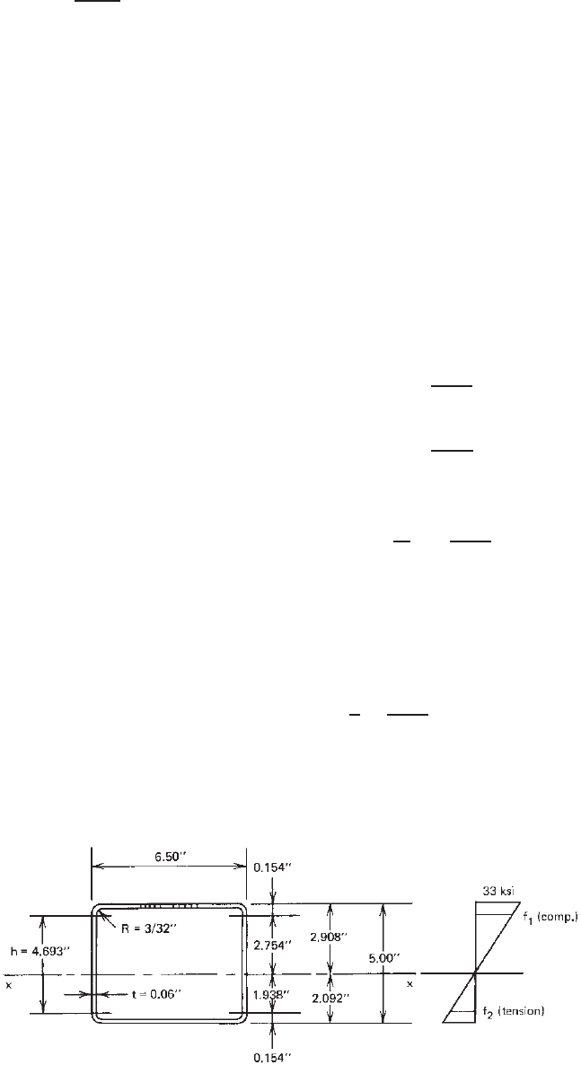
Example 3.4 For the box section used in Example 3.3,
it can be shown that the distance from the top compres-
sion fiber to the neutral axis is 2.908 in. if the beam
webs are fully effective. Check these two beam webs and
determine whether they are fully effective according to
Eqs. (3.54)–(3.56) for strength determination. Use F
y
=
33 ksi and the U.S. customary unit.
SOLUTION. From Fig. 3.31, stresses f
1
and f
2
are
computed as follows:
f
1
= 33
2.754
2.908
= 31.25 ksi (compression)
f
2
= 33
1.938
2.908
= 22.00 ksi (tension)
According to Eqs. (3.54) for webs under a stress gradient,
ψ =
f
2
f
1
=
22.00
31.25
= 0.704
k = 4 + 2(1 + ψ)
3
+ 2(1 + ψ)
= 4 +2(1 + 0.704)
3
+ 2(1 + 0.704) = 17.304
h = 4.693 in.
h
t
=
4.693
0.06
= 78.21 < 200 OK
(see Section 3.2 for the maximum h/t ratio). The effec-
tive depth b
e
of the web can be computed in accordance
Figure 3.31 Example 3.4.