Yu W., LaBoube R.A. Cold-Formed Steel Design
Подождите немного. Документ загружается.

ADDITIONAL INFORMATION 95
for a multiple-hole pattern that fits within a noncircular
virtual hole, while Fig. 3.65 illustrates the dimension d
h
for a rectangular hole that exceeds the limits of 2.5 in.
(64 mm) × 4.5 in. (114 mm) but still fits within an allowable
circular virtual hole. For each case, the provisions apply to
the geometry of the virtual hole, not the actual hole or
holes.
1.333
For the effect of web holes on the shear strength and
web crippling strength of C-sections, see Section 4.3 on
the design of beam webs.
3.7 PLATE BUCKLING OF STRUCTURAL
SHAPES
Section 3.5 discussed the local buckling of s tiffened and
unstiffened compression elements, for which the edges were
assumed to be simply supported. If the actual restraining
effects of adjoining cross-sectional elements are taken into
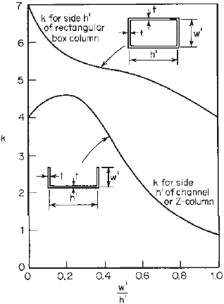
account, the plate buckling coefficient k for box sections,
channels, and Z-sections used as columns can be found
from Fig. 3.66. These curves are based on the charts
developed by Kroll, Fisher, and Hei-merl.
3.116
Additional
information can be found from Refs. 1.94, 1.158, 3.8,
3.80, 3.117–3.123, 3.195, and 3.196 and in Chapter 5 on
compression members.
The advantages of using a numerical solution for the
design of cold-formed steel members a re discussed by
Schafer and Pekoz in Refs. 3.195 and 3.196. The element
interaction can be handled properly by the numerical
solution.
Since 2001, the AISI North American specification
permits the use of rational analysis for determining the
design strength and stiffness of cold-formed steel members
in Section A1.2. Consequently, Appendix 1, Design of
Cold-Formed Steel Structural Members Using the Direct
Strength Method, was developed in 2004 and added in
Figure 3.66 Plate buckling coefficient k for side h
of columns.
the 2007 edition of the North American Specification. For
details, see Chapter 15.
3.8 ADDITIONAL INFORMAT ION
The strength of thin compression elements and the current
design criteria were discussed in this chapter on the basis of
the publications referred to in the text. Additional informa-
tion on the strength of compression elements and members
can also be found from the publications included in the list
of references for this chapter.
The structural behavior of webs of beams subjected to
shear or bearing is discussed in Chapter 4 on the design
of flexural members. The buckling behavior of closed
cylindrical tubular members is discussed in Chapter 7.

CHAPTER 4
Flexural Members
4.1 GENERAL REMARKS
Beams are used to support transverse loads and/or applied
moment. Cold-formed steel sections such as I-sections,
C-sections (channels), Z-shapes, angles, T-sections, hat
sections, and tubular members (Fig. 1.2) and decks and
panels (Fig. 1.11) can be used as flexural members.
In the design of cold-formed steel flexural members,
consideration should first be given to the moment-resisting
capacity and the stiffness of the member. It may be found
that in many cases the moment of inertia of the section
is not a constant value but varies along the span length
due to the noncompactness of the thin-walled section and
the variation of the moment diagram. The design method
is discussed in this chapter. Second, the webs of beams
should be checked for shear, combined bending and shear,
web crippling, and combined bending and web crippling.
In addition to the design features discussed above, the
moment-resisting capacity of the member may be limited by
lateral-torsional buckling of the beam, particularly when the
open section is fabricated from thin material and laterally
supported at relatively large intervals. For this reason,
flexural members must be braced adequately in accordance
with the bracing requirements prescribed in the North
American Specification; otherwise a low design moment
has to be used. For some open sections with edge-stiffened
compression flanges, distortional buckling may be critical.
Unlike hot-rolled heavy s teel sections, in the design
of thin-walled cold-formed steel beams, special problems
such as shear lag and flange curling are also considered
to be important matters due to the use of thin material.
Furthermore, the design of flexural members can be even
more involved if the increase of steel mechanical properties
due to cold work is to be utilized.
Based on the above general discussion, the following
design features are considered in this chapter with some
design examples for the purpose of illustration:
1. Bending strength and deflection
2. Design of webs for shear, combined bending and
shear, web crippling, and combined bending and web
crippling
3. Bracing requirements
4. Shear lag
5. Flange curling
In general, long-span, shallow beams are governed by
deflection and medium-length beams are controlled by
bending strength. For short-span beams, shear strength may
be critical.
For design tables and charts, reference should be made
to Part II of the AISI Design Manual.
1.349
4.2 BENDING STRENGTH AND DEFLECTION
4.2.1 Introduction
In the design of flexural members, sufficient bending
strength must be provided, and at the same time the deflec-
tion of the member under s ervice loads should not exceed
specific limitations.
A. ASD Method
According to the design format discussed in Section
3.3.1.1 for the A SD method, Eq. (4.1) gives the
following structural safety requirement for the flexural
or bending strength:
M ≤ M
a
(4.1)
where M is the required flexural strength or bending
moment for ASD computed from the load combinations
discussed in Section 3.3.1.2 and M
a
is the allowable
flexural strength or bending moment determined by Eq.
(4.2):
M
a
=
M
n
b
(4.2)
where
b
= 1.67 is the safety factor for flexural or
bending strength on the basis of Section C 3.1 of the
North American Specification and M
n
is the smallest
nominal flexural strength or moment determined from
the following five design considerations:
1. Section strength or bending moment of the cross
section calculated in accordance with Section 4.2.2
2. Lateral-torsional buckling strength calculated in
accordance with Section 4.2.3
97
98 4 FLEXURAL MEMBERS
3. Distortional buckling strength calculated in accor-
dance with Section 4.2.4 for I-, Z-, C - and other
open cross-sectional beams having edge-stiffened
compressions flanges
4. Section strength of beams having one flange through
fastened to deck or sheathing determined in accor-
dance with Section 4.2.5
5. Section strength of beams having one flange fastened
to a standing seam roof system determined in accor-
dance with Section 4.2.6
In addition to the above-listed five cases, consid-
eration should also be given to shear lag problems
for unusually short span beams (see Section 4.2.7).
The current North American design provisions consider
torsional effects in Section C3.6 of the Specification
for the loads that do not pass through the shear center
of the cross section.
1.345
For torsional analysis, see
Appendix B.
B. LRFD Method
Based on the design format discussed in Section
3.3.2.1 for the LRFD method, the structural safety
requirement for the flexural or bending strength is
expressed in Eq. (4.3):
M
u
≤ φ
b
M
n
(4.3)
where M
u
is the required flexural strength or bending
moment for LRFD computed from load combinations
(see Section 3.3.2.2);
φ
b
, the resistance factor for reducing the flex-
ural strength or bending moment, equals 0.95 for the
nominal section strength of flexural members with stiff-
ened or partially stiffened compression flanges (Section
4.2.2) and 0.90 for the nominal section strength of
flexural members w ith unstiffened compression flanges
(Section 4.2.2), the nominal lateral–torsional buckling
strength (Section 4.2.3), the nominal distortional
buckling strength (Section 4.2.4), the section strength
of beams having one flange through fastened to deck
or sheathing (Section 4.2.5), and the section strength of
beams having one flange fastened to a standing seam
roof system (Section 4.2.6); and φ
b
M
n
is the design
flexural strength or bending moment, w here M
n
was
defined above for the ASD method.
C. LSD Method
Based on the design format discussed in Section
3.3.3.1 for the LSD method, the structural safety
requirement for the flexural or bending strength is
expressed as
M
f
≤ φ
b
M
n
where M
f
is the required flexural resistance for LSD
computed from load combinations (see Section 3.3.3.2);
M
n
is the nominal flexural resistance; and φ
b
equals 0.90
for the nominal section resistance (Section 4.2.2), the
nominal lateral–torsional buckling resistance (Section
4.2.3), and the nominal flexural resistance of beams
having one flange through fastened to deck or sheathing
(Section 4.2.5) and 0.85 for the nominal distortional
buckling resistance (Section 4.2.4), where φ
b
M
n
is the
factored flexural resistance.
4.2.2 Section Strength or Bending Moment
of the Cross Section
Section C3.1.1 of the 2007 edition of the North American
specification includes two design procedures for calculating
the section strength of flexural members. Procedure I is
based on “initiation of yielding” and procedure II is based
on “inelastic reserve capacity.” Both design procedures are
discussed here.
4.2.2.1 Initiation of Yielding In procedure I of the AISI
specification, the nominal moment M
n
of the cross section
is the effective yield moment M
y
determined on the basis
of the effective areas of flanges and the beam web. The
effective width of the compression flange and the effec-
tive depth of the web can be computed from the design
equations presented in Chapter 3.
Similar to the design of hot-rolled steel shapes, the yield
moment M
y
of a c old-formed steel beam is defined as
the moment at which an outer fiber (tension, compression,
or both) first attains the yield stress of steel. This is the
maximum bending capacity to be used in elastic design.
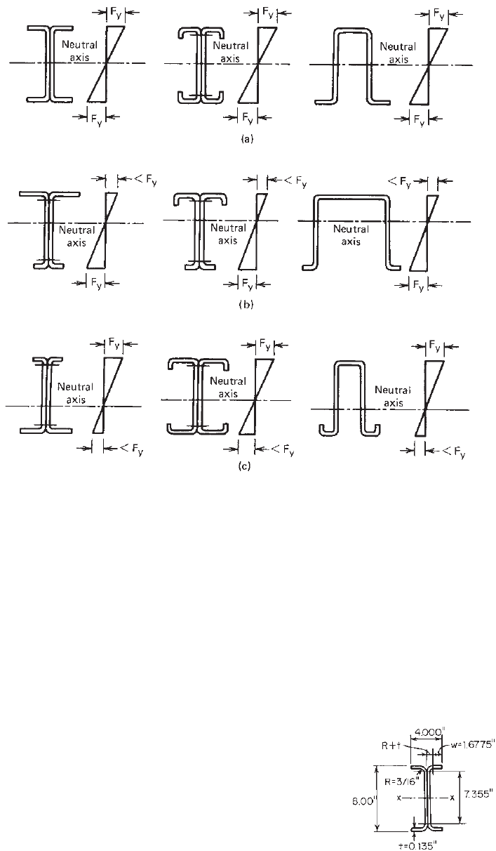
Figure 4.1 shows s everal types of stress distribution for
yield moment based on different locations of the neutral
axis. For balanced sections (Fig. 4.1a), the outer fibers in
the compression and tension flanges reach the yield stress at
the same time. However, if the neutral axis is eccentrically
located, as shown in Figs. 4.1b and c, the initial yielding
takes place in the tension flange for case b and in the
compression flange for case c.
Based on the above discussion, the nominal section
strength for initiation of yielding is calculated by using Eq.
(4.4):
M
n
= M
y
= S
e
F
y
(4.4)
where F
y
= design yield stress
S
e
= elastic section modulus of effective section
calculated with extreme c ompression or
tension fiber a t F
y
In cold-formed steel design, S
e
is usually computed by
using one of the following two cases:
1. If the neutral axis is closer to the tension than to
the compression flange, as shown in Fig. 4.1c,the
BENDING STRENGTH AND DEFLECTION 99
Figure 4.1 Stress distribution for yield moment: (a) balanced sections; (b) neutral axis close
to compression flange (initial yielding in tension flange); (c) neutral axis close to tension flange
(initial yielding in compression flange).
maximum stress occurs in the compression flange, and
therefore the plate slenderness factor λ and the effec-
tive width of the compression flange are determined
by the w /t ratio and f = F
y
in Eq. (3.44). Of course,
this procedure is also applicable to those beams for
which the neutral axis is located at the middepth of
the section, as shown in Fig. 4.1a.
2. If the neutral axis is closer to the compression than
to the tension flange, as shown in Fig. 4.1b,the
maximum stress of F
y
occurs in the tension flange.
The stress in the compression flange depends on the
location of the neutral axis, which is determined by
the effective area of the section. The latter cannot be
determined unless the compressive stress is known.
The closed-form solution of this type of design is
possible but would be a very tedious and complex
procedure. It is therefore customary to determine
the sectional properties of the section by successive
approximation.
The calculation of the nominal moment on the basis of
initiation of yielding and the determination of the design
moment are illustrated in Examples 4.1–4.4.
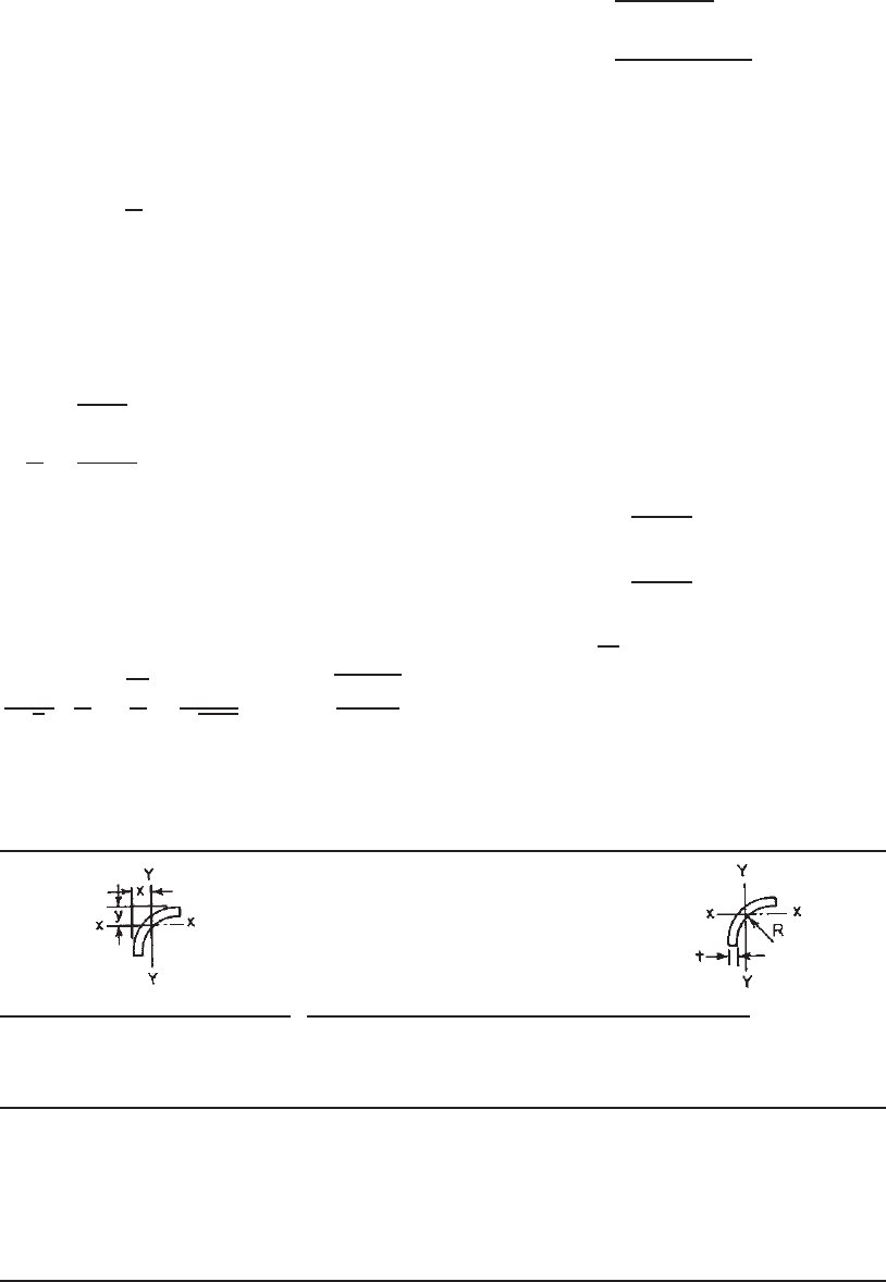
Example 4.1 Use the ASD and LRFD methods to check
the adequacy of the I-section with an unstiffened compres-
sion flange as shown in Fig. 4.2. The nominal moment for
section strength is computed on the basis of initiation of
Figure 4.2 Example 4.1.
100 4 FLEXURAL MEMBERS
yielding by using F
y
= 50 ksi. Assume that lateral bracing
is adequately provided. The dead-load moment M
D
=
30 in.-kips and the live-load moment M
L
= 150 in.-kips.
SOLUTION
A. ASD Method
1. Calculation of Sectional Properties. The sectional
properties of the corner element can be obtained from
Table 4.1. For R =
3
16
in. and t = 0.135 in.,
I
x
= I
y
=0.0003889 in.
4
A = 0.05407 in.
2
x = y = 0.1564 in.
For the unstiffened flange,
w =
4.000
2
− (R + t) = 1.6775 in.
w
t
=
1.6775
0.135
= 12.426 < 60
OK according to Section 3.2
Since the compression flange is an unstiffened
element and the neutral axis is either at middepth or
closer to the tension flange, use Eqs. (3.41)–(3.44)
with k = 0.43 and f = F
y
= 50 ksi. Therefore
λ =
1.052
√
k
w
t
f
E
=
1.052
√
0.43
(12.426)
50
29,500
= 0.821 > 0.673 [Eq. (3.44)]
ρ =
1 − 0.22/λ
λ
=
1 − 0.22/0.821
0.821
= 0.892 [Eq. (3.43)]
b = ρw = 0.892(1.6775)
= 1.4963 in.
By using the effective width of the compression
flange and a ssuming the web is fully effective, the
location of the neutral axis, the moment of inertia
I
x
and the elastic section modulus of the effec-
tive section S
e
can be computed as shown in table
on the following page.
Since y
cg
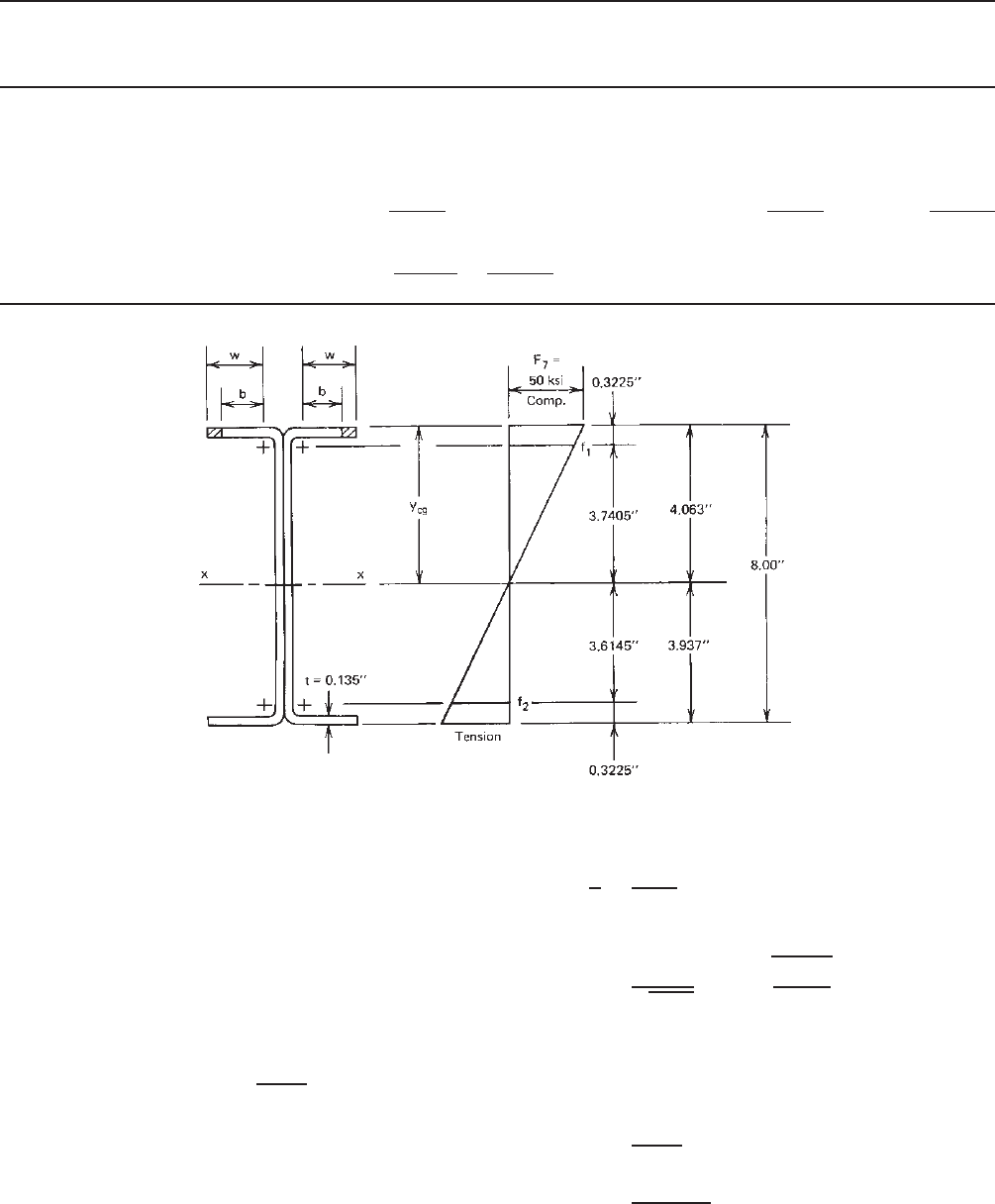
>d/2 = 4.00 in., initial yield occurs
in the compression flange. Prior to computing the
moment of inertia, check the web for full effec-
tiveness by using Fig. 4.3 and Section 3.5.1.2 as
follows:
f
1
= 50
3.7405
4.063
= 46.03 ksi (compression)
f
2
= 50
3.6145
4.063
= 44.48 ksi (tension)
ψ =
f
2
f
1
= 0.966
k = 4 + 2(1 + ψ)
3
+ 2(1 + ψ)
= 4 +2(1 + 0.966)
3
+ 2(1 + 0.966) = 23.13
[Eq. (3.54)]
Table4.1 One90
◦
Corner, Dimensions and Properties
Dimensions Properties
Centroid
Inside Moment of Coordinates Blank
Thickness t (in.) Radius R (in.) Inertia I
x
= I
y
(in.
4
) x = y (in.) Area A (in.
2
) Width (in.)
0.135 0.1875 0.0003889 0.1564 0.05407 0.3652
0.105 0.1875 0.0002408 0.1373 0.03958 0.3495
0.075 0.0938 0.0000301 0.0829 0.01546 0.1865
0.060 0.0938 0.0000193 0.0734 0.01166 0.1787
0.048 0.0938 0.0000128 0.0658 0.00888 0.1724
0.036 0.0625 0.00000313 0.0464 0.00452 0.1170
Notes: (1) Stock width of blank taken at t/3 distance from inner surface.
(2) 1 in. = 25.4 mm.
BENDING STRENGTH AND DEFLECTION 101
Distance from
Top Fiber yAy Ay
2
Element Area A (in.
2
)(in.)(in.
3
)(in.
4
)
Top flange 2(1.4963)(0.135) = 0.4040 0.0675 0.0273 0.0018
Top corners 2(0.05407) = 0.1081 0.1564 0.0169 0.0026
Webs 2(7.355)(0.135) = 1.9859 4.0000 7.9436 31.7744
Bottom corners 2(0.05407) = 0.1081 7.8436 0.8479 6.6506
Bottom flange 2(1.6775)(0.135) =
0.4529 7.9325 3.5926 28.4983
Total 3.0590 12.4283 66.9277
y
cg
=
(Ay)
A
=
12.4283
3.0590
= 4.063 in.
Figure 4.3 Stress distribution in webs.
From Fig. 4.2,
h
o
= out-to-out depth of web
= 8.00 in.
b
o
= out-to-out width of the compression
flange of each channel = 2.00 in.
Since h
o
/b
o
= 4, then use Eq. (3.55a),
b
1
=
b
e
3 + ψ
where b
e
is the effective width of the web deter-
mined in accordance with Eqs. (3.41)–(3.44) with f
1
substitued for f and k = 23.13 as follows:
h = 7.355 in.
h
t
=
7.355
0.135
= 54.48 < 200
OK according to Section 3.2
λ =
1.052
√
23.13
(54.48)
46.03
29,500
= 0.471 < 0.673
[Eq. (3.44)]
ρ = 1.0 [Eq. (3.43)]
b
e
= h = 7.355 in.
b
1
=
b
e
3 + ψ
=
7.355
3 + 0.966
= 1.855 in. [Eq. (3.55a)]
102 4 FLEXURAL MEMBERS
Since ψ>0.236,
b
2
=
1
2
b
e
= 3.6775 in. [Eq. (3.55b)]
b
1
+ b
2
= 1.855 + 3.6775 = 5.5325 in.
Since b
1
+ b
2
is greater than the compression portion
of the web of 3.7405 in., the web is fully effective a s
assumed. The total I
x
is determined as
(Ay
2
) = 66.9277
2I
web
= 2(
1
12
)(0.135)(7.355)
3
= 8.9522
−
A
(y
cg
)
2
= (3.0590)(4.063)
2
=−50.4979
I
x
= 25.3820 in.
4
The elastic section modulus relative to the top
fiber is
S
e
=
I
x
y
cg
=
25.3820
4.063
= 6.247 in.
3
2. Nominal and Allowable Moments. The nominal
moment for section strength is
M
n
= S
e
F
y
= (6.247)(50) = 312.35 in.-kips
Theallowablemomentis
M
a
=
M
n
b
=
312.35
1.67
= 187.0in.-kips
3. Required Moment. Based on the ASD load combina-
tion discussed in Section 3.3.1.2, the required moment
for the given dead-load moment and live-load moment
is computed as follows:
M = M
D
+ M
L
= 30 + 150 = 180 in.-kips
Since M <M
a
, the I-section is adequate for the ASD
method.
B. LRFD Method
1. Nominal and Design Moments. The nominal moment
for the LRFD method is the same as that used for the
ASD method, that is,
M
n
= 312.35 in.-kips
The design moment for the I-section having an unstiff-
ened compression flange (φ
b
= 0.90) is
φ
b
M
n
= 0.90(312.35) = 281.12 in.-kips
2. Required Moment. According to the load factors and
the load combinations discussed in Section 3.3.2.2,
the required moment for the given dead-load moment
and live-load moment can be computed as follows:
M
u1
= 1.4D
= 1.4(30) = 42.00 in.-kips
M
u2
= 1.2D + 1.6L
= 1.2(30) + 1.6(150)
= 276.00 in.-kips ⇐ controls
Since M
u
<φ
b
M
n
, the I-section is also adequate for
the LRFD method.
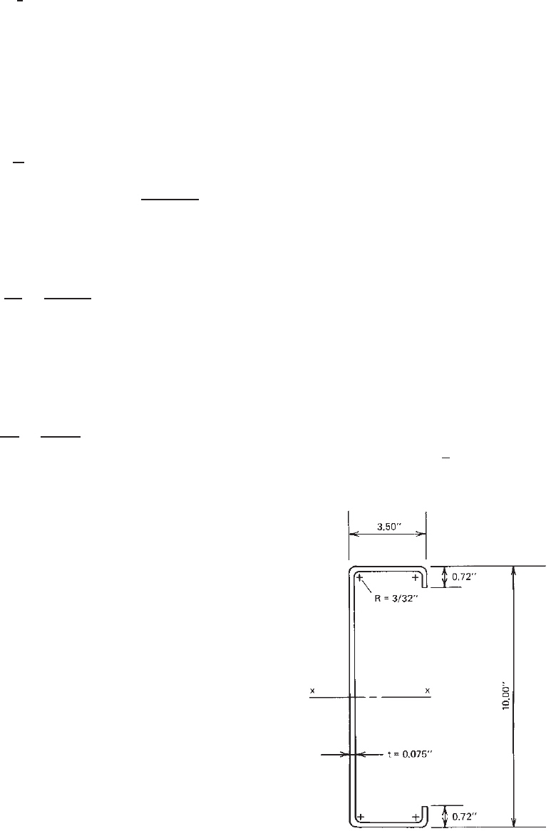
Example 4.2 For the C-section with an edge stiffener as
shown in Fig. 4.4, determine the allowable moment (M
a
)
about the x axis for the ASD method and the design moment
(φ
b
M
n
) for the LRFD method. Assume that the yield stress
of steel is 50 ksi and that lateral bracing is adequately
provided. Use the linear method. The nominal moment is
determined by initiation of yielding.
SOLUTION
A. ASD Method
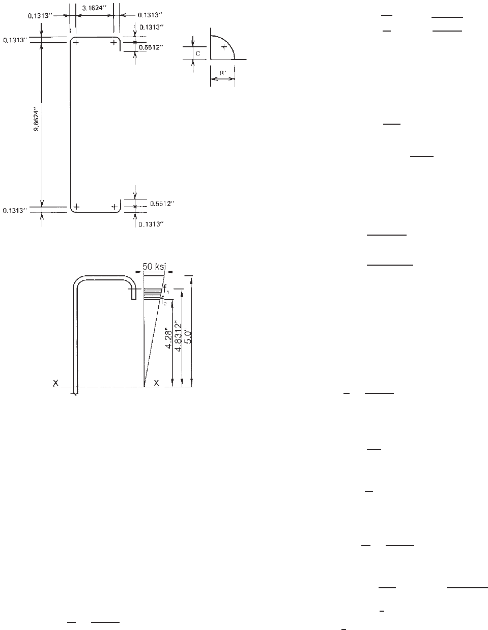
1. Calculation of Sectional Properties. In order to
simplify the calculation, line elements, as shown in
Fig. 4.5a, are used for the linear method.
i. Corner Element (Figs. 1.32 and 4.5a)
R
= R +
1
2
t = 0.131 in.
Figure 4.4 Example 4.2 (same as Fig 3.50).
BENDING STRENGTH AND DEFLECTION 103
(a)
(
b
)
Figure 4.5 (a) Line elements. ( b) Compression stresses f
1
and f
2
.
Arc length:
L = 1.57R
= 0.206 in.
c = 0.637R
= 0.0836 in.
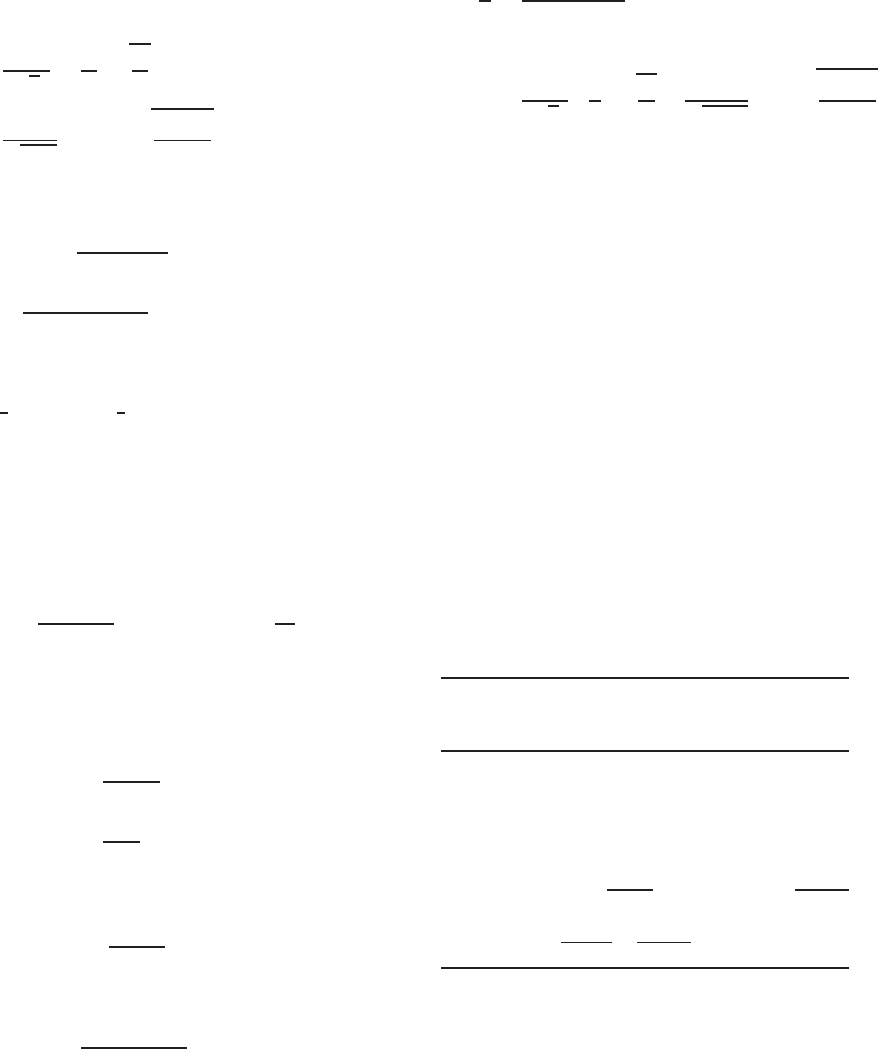
ii. Effective Width of the Compression Flange. For the
given C-section with equal flanges, the neutral axis
is located either at the middepth or closer to the
tension flange. Therefore, use f = F
y
= 50 ksi to
compute the effective width of the compression
flange according to Section 3.5.3.1a. For the
compression flange,
w = 3.50 − 2(R + t) = 3.1624 in.
w
t
=
3.1624
0.075
= 42.17
From Eq. (3.80)
S = 1.28
E
f
= 1.28
29,500
50
= 31.09
0.328S = 10.20
Since w/t > 0.328 S , use Eq. (3.81) to compute
the required moment of inertia of the edge stiffener
I
a
as follows:
I
a
= 399t
4
w/t
S
− 0.328
3
= 399(0.075)
4
42.17
31.09
− 0.328
3
= 13.73 × 10
−3
in.
4
The above computed value should not exceed the
following value:
I
a
=
115(w/t)
S
+ 5
t
4
=
115(42.17)
31.09
+ 5
(0.075)
4
= 5.093 × 10
−3
in.
4
Therefore, use I
a
= 5.093 × 10
−3
in.
4
For the
simple lip edge stiffener used for the given channel
section,
D = 0.720 in.
d = D − (R + t) = 0.5512 in.
d
t
=
0.5512
0.075
= 7.35
By using Eq. (3.83), the moment of inertia of the
full edge stiffener is
I
s
=
d
3
t
12
= 1.047 × 10
−3
in.
4
From Eq. (3.82),
R
I
=
I
s
I
a
= 0.206 < 1.0OK
The effective width b of the compression flange
can be calculated as follows:
D
w
=
0.72
3.1624
= 0.228
From Eq. (3.84),
n = 0.582 −
w/t
4S
= 0.582 −
42.17
4 × 31.09
= 0.243 <
1
3
Use n =
1
3
.
104 4 FLEXURAL MEMBERS
Since D/w<0.25 and θ = 90
◦
for the simple lip
edge stiffened, from Table 3.5
k = 3.57(R
I
)
n
+ 0.43
= 3.57(0.206)
1/3
+ 0.43 = 2.54 < 4.0OK
Use k = 2.54 to calculate the plate slenderness
factor for the compression flange as follows:
λ =
1.052
√
k
w
t
f
E
=
1.052
√
2.54
(42.17)
50
29,500
= 1.146 > 0.673
The effective width of the compression flange is
b = ρw =
1 − 0.22/λ
λ
w
=
1 − 0.22/1.146
1.146
(3.1624) = 2.230 in.
From Eqs. (3.77) and (3.78),
b
1
=
1
2
(b)(R
I
) =
1
2
×2.230
(0.206) =0.230 in.
b
2
= b − b
1
= 2.230 − 0.230 = 2.00 in.
iii. Reduced Effective Width of the Edge Stiffener. The
effective width of the edge stiffener under a stress
gradient can be determined according to Section
3.5.2.2. From Eq. (3.64),
k =
0.578
ψ +0.34
where ψ =
f
2
f
1
In the above equations, the compression stresses f
1
and f
2
(Fig 4.5b) are calculated on the basis of the
gross section as follows:
f
1
= 50
4.8312
5.0
= 48.312 ksi
f
2
= 50
4.28
5.0
= 42.80 ksi
Therefore
ψ =
42.80
48.312
= 0.886
and
k =
0.578
0.886 + 0.34
= 0.471
The k value of 0.471 calculated above for the
edge stiffener under the stress gradient is slightly
larger than the k value of 0.43 for unstiffened
elements under uniform compression.
The effective width of the edge stiffener can be
determined as follows:
d
t
=
D − (R + t)
t
= 7.35
f = f
1
= 48.312 ksi
λ =
1.052
√
k
d
t
f
E
=
1.052
√
0.471
(7.35)
48.312
29,500
= 0.456 < 0.673
ρ = 1.0
The effective width of the edge stiffener is
d
s
= d = 0.551 in.
The reduced effective width of the edge stiff-
ener is
d
s
= d
s
(R
I
) = 0.551(0.206) = 0.113 in.
The above calculation indicates that the compres-
sion stiffener is not fully effective.
iv. Location of Neutral Axis and Computation of I
x
and S
x
a. Location of Neutral Axis Based on Full Web
Element. Assuming that the web element
(element 7 in Fig. 4.6) is fully effective,
the neutral axis can be located by using the
following table. See Fig. 4.6 for dimensions of
elements.
Effective Distance from
Length Top Fiber Ly
Element L (in.) y (in.) (in.
2
)
1 0.5512 9.5556 5.2670
2 2(0.206) = 0.4120 9.9148 4.0849
3 3.1624 9.9625 31.5054
4 2(0.206) = 0.4120 0.0852 0.0351
5 2.2300 0.0375 0.0836
6 0.1130 0.2254 0.0255
7
9.6624 5.0000 48.3120
Total 16.5430 89.3135
y
cg
=
(Ly)
L
=
89.3135
16.5430
= 5.399 in.
Use Section 3.5.1.2 in this volume or Section
B2.3 of the North American Specification to
check the effectiveness of the web element.