Yu W., LaBoube R.A. Cold-Formed Steel Design
Подождите немного. Документ загружается.

STRUCTURAL BEHAVIOR OF COMPRESSION ELEMENTS AND DESIGN CRITERIA 75
with Eqs. (3.41)–(3.44) for uniformly compressed stiffened
elements with f
1
substituted for f, h/t substituted for w/t,
and the k value computed above. From Eq. (3.44),
λ =
1.052
√
k
h
t
f
1
E
=
1.052
√
17.304
(78.21)
31.25
29,500
= 0.644
Since λ<0.673, b
e
= h = 4.693 in. Because h
0
/b
0
=
5.00/6.50 < 4andψ>0.236, Eqs. (3.55a)and(3.55b)
are used to compute b
1
and b
2
as follows:
b
1
=
b
e
3 + ψ
=
4.693
3 + 0.704
= 1.267 in.
b
2
=
1
2
b
e
= 2.347 in.
b
l
+ b
2
= 1.267 + 2.347 = 3.614 in.
Since b
1
+ b
2
> 2.754 in., the compression portion of the
web is fully effective.
3.5.2 Unstiffened Compression Elements
3.5.2.1 Unstiffened Elements under Uniform
Compression
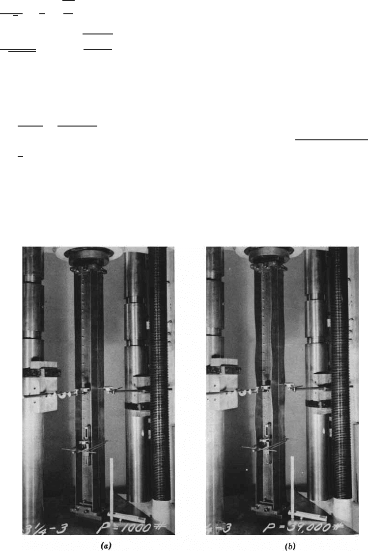
Yielding. An unstiffened compression element, such as
the flange of the I-shaped column shown in Fig. 3.32a,
may fail in yielding if the column is short and its w/t ratio
is less than a certain value. It may buckle as shown in
Fig. 3.32b at a predictable unit stress, which may be less
than the yield stress, when its w/t ratio exceeds that limit.
Local Buckling. The elastic critical local buckling stress
for a uniformly compressed plate can also be determined
by Eq. (3.16), which gives
f
cr
=
kπ
2
E
12(1 − μ)
2
(w/t)
2
where E = modulus of elasticity
μ = Poisson’s ratio
w/t = flat width–thickness ratio
k = constant depending upon conditions of edge
support and aspect ratio a/w
Figure 3.32 Local buckling of unstiffened compression elements.
1.6
76 3 STRENGTH OF THIN ELEMENTS AND DESIGN CRITERIA
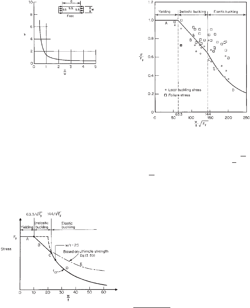
Figure 3.33 Buckling coefficient for rectangular plates simply
supported along three sides with one unloaded edge free.
3.7
For a long rectangular plate simply supported along three
sides, with one unloaded free edge as shown in Fig. 3.33,
k = 0.425. However, when the restraining effect of the web
is considered, k may be taken as 0.5 for the design of an
unstiffened compression flange.
If the steel exhibits sharp yielding and an unstiffened
compression element is ideally plane, the element will
buckle at the critical stress determined by Eq. (3.16) with
the upper limit of F
y
(Fig. 3.34). However, such ideal
conditions may not exist, and an element with a moderate
w/t ratio may buckle below the theoretical elastic buckling
stress.
On the basis of experimental evidence a straight line B
is drawn in Fig. 3.34 representing those s tresses at which
sudden and pronounced buckling occurred in the tests. The
1980 edition of the AISI Specification considered that the
Figure 3.34 Maximum stress for unstiffened compression
elements.
1.161
Figure 3.35 Correlation between test data on unstiffened
compression elements and predicted maximum stress.
1.161,3.13
upper limit of such buckling is at w/t = 63.3/
F
y
and
the endpoint of the line is at w/t = 144/
√
F
y
.
3.68∗
In
this region the element will buckle inelastically. If w/t ≤
63.3/
F
y
, the element will fail by yielding, represented by
horizontal line A.
Additional e xperimental and analytical investigations on
the local buckling of unstiffened compression elements in
the elastic range have been conducted by Kalyanaraman,
Pekoz, and Winter.
3.8,3.69–3.71
These studies considered the
effects of initial imperfection and rotational edge restraint
on the local buckling of compression elements. By using the
procedure outlined in Ref. 3.8, a more realistic value of the
local buckling coefficient can be calculated for compression
elements of cold-formed steel members.
Figure 3.35 shows the correlation between some test data
and the predicted maximum stresses.
Postbuckling Strength. When the w/t ratio of an unstiff-
ened element exceeds about 25, the element distorts more
gradually at a stress about equal to the theoretical local
buckling stress (curve D in Fig. 3.34) and returns to its
original shape upon unloading because the buckling stress
is considerably below the yield stress. Sizable waving can
∗
When the yield stress of steel is less than 33 ksi (228 MPa or 2320
kg/cm
2
), the endpoint of line B is w/t = 25.
STRUCTURAL BEHAVIOR OF COMPRESSION ELEMENTS AND DESIGN CRITERIA 77
occur without permanent set being caused by the additional
stress due to distortion. Such compression elements show
a considerable postbuckling strength.
Based upon the tests made on cold-formed steel sections
having unstiffened compression flanges, the following
equation has been derived by Winter for the effective
width of unstiffened compression elements, for which the
postbuckling strength has been considered
3.13
:
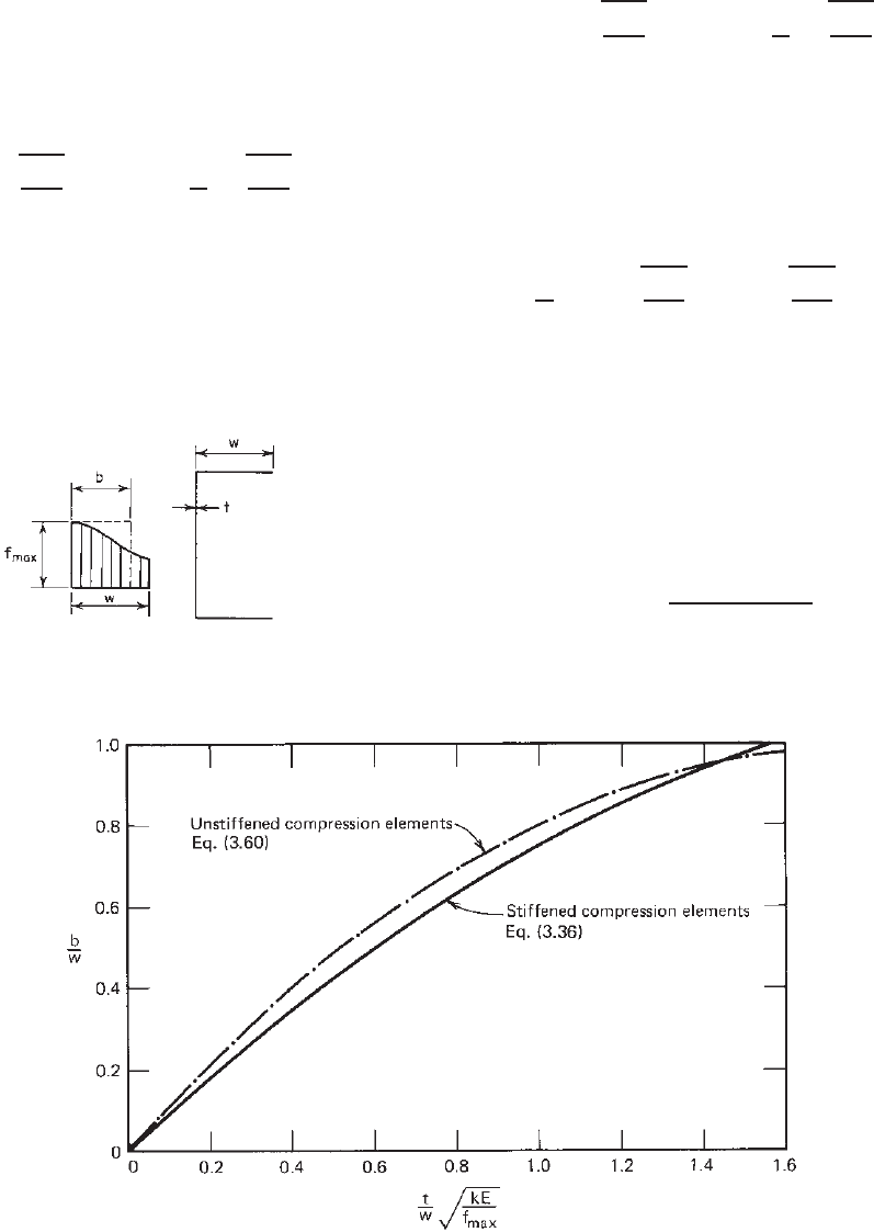
b = 0.8t
E
f
max
1 − 0.202
t
w
E
f
max
(3.59)
where f
max
is the stress in the unstiffened compression
element at the supported edge (Fig. 3.36). Curve E in
Fig. 3.34 is based on Eq. (3.59) and represents the ultimate
strength of the element, which is considerably larger than
the elastic buckling stress.
Figure 3.36 Effective width of unstiffened compression element.
Based on a selected local buckling coefficient of k = 0.5,
Eq. (3.59) can be generalized as follows:
b = 1.13t
kE
f
max
1 − 0.286
t
w
kE
f
max
(3.60)
where k is the local buckling coefficient for unstiffened
compression elements. Figure 3.37 shows a comparison
between Eq. (3.36) for stiffened elements and Eq. (3.60)
for unstiffened elements.
Equation (3.59) can also be written in terms of
f
cr
/f
max
as
b
w
= 1.19
f
cr
f
max
1 − 0.3
f
cr
f
max
(3.61)
where f
cr
is the e lastic local buckling stress determined by
Eq. (3.16) with a value of k = 0.5. The above equation
is practically identical to the empirical formula derived by
Kalyanaraman et al. on the basis of some additional results
of tests.
3.70
Based on Eq. (3.61), the reduction factor ρ for the effec-
tive width design of unstiffened elements can be determined
as follows:
ρ =
1.19(1 − 0.3/λ)
λ
(3.62)
where λ is defined in Eq. (3.44).
Figure 3.37 Comparison of generalized equations for stiffened and unstiffened compression
elements.
78 3 STRENGTH OF THIN ELEMENTS AND DESIGN CRITERIA
Prior to 1986, it had been a general practice to design
cold-formed steel members with unstiffened flanges by
using the allowable stress design approach. The effective
width equation was not used in the AISI Specification
due to lack of extensive experimental verification and the
concern for excessive out-of-plane distortions at service
loads.
In the 1970s, the applicability of the effective width
concept to unstiffened elements under uniform compres-
sion was studied in detail by Kalyanaraman, Pekoz, and
Winter.
3.69–3.71
The evaluation of the test data using
k = 0.43 is presented and summarized by Pekoz in
Ref. 3.17, which shows that Eq. (3.43) gives a conser-
vative lower bound to the test results of unstiffened
compression elements. In addition to the strength determi-
nation, the same study also investigated the out-of-plane
deformations in unstiffened e lements. The results of
theoretical calculations and test results on sections having
unstiffened elements with w/t = 60 are presented in
Ref. 3.17. It was found that the maximum amplitude of
the out-of-plane deformations at failure can be twice the
thickness as the w/t ratio approaches 60. However, the
deformations are significantly less at service loads.
Based on the above reasons and justifications, the
following provisions were included for the first time in
Section B3.1 of the 1986 AISI Specification for the design
of uniformly compressed unstiffened elements. The same
approach was used in the 1996 Specification and is retained
in the North American specification:
(a) Strength Determination. The effective w idths b of
unstiffened compression elements with uniform
compression are determined in accordance with
Eqs. (3.41)–(3.44) with the exception that k is taken a s
0.43 and w is as defined in Section 3.2. See Fig. 3.5.
(b) Serviceability Determination. The effective widths
b
d
used in determining serviceability are calculated
in accordance with Eqs. (3.45)–(3.47) except that
k = 0.43.
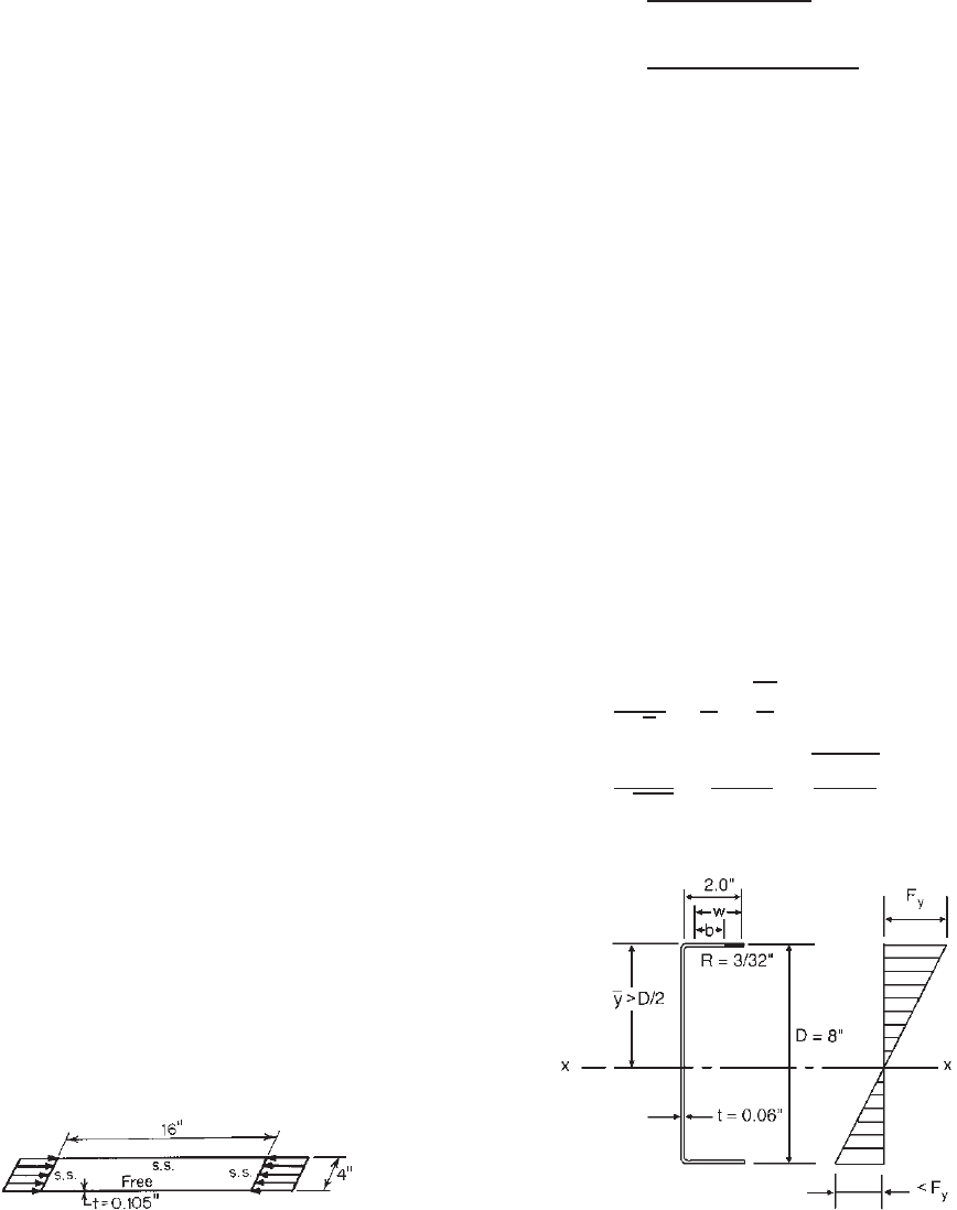
Example 3.5 Determine the critical buckling stress and
critical buckling load for the thin sheet simply supported at
three edges and one edge free, as shown in Fig. 3.38. Use
U.S. customary unit.
Figure 3.38 Example 3.5.
SOLUTION
1. The critical buckling stress of the unstiffened
compression element based on Eq. (3.16) is
f
cr
=
kπ
2
E
12(1 − μ
2
)(w/t)
2
=
0.425π
2
(29.5 × 10
3
)
12(1 − 0.3
2
)(4/0.105)
2
= 7.808 ksi
In the above calculation, the value of k = 0.425 is
slightly conservative (see Fig. 3.33).
2. The critical buckling load is
P
cr
= Af
cr
= 4(0.105)(7.808) = 3.279 kips
Example 3.6 Calculate the effective width of the
compression flange of the channel section (Fig. 3.39) to be
used as a beam. Use F
y
= 33 ksi. Assume that the beam
web is fully effective and that lateral bracing is adequately
provided. Use U.S. customary unit.
SOLUTION. Because the compression flange of the given
channel is a uniformly compressed unstiffened element
which is supported at only one edge parallel to the direction
of the stress, the effective width of the flange for strength
determination can be computed by using Eqs. (3.41)–(3.44)
with k = 0.43.
According to Eq. (3.44), the slenderness factor λ for
f = F
y
is
λ =
1.052
√
k
w
t
f
E
=
1.052
√
0.43
1.8463
0.06
33
29,500
= 1.651
Figure 3.39 Example 3.6.
STRUCTURAL BEHAVIOR OF COMPRESSION ELEMENTS AND DESIGN CRITERIA 79
Figure 3.40 Unstiffened lip subjected to stress gradient.
Since λ>0.673, use Eqs. (3.42) and (3.43) to calculate the
effective width b as follows:
b = ρw =
1 − 0.22/λ
λ
w
=
1 − 0.22/1.651
1.651
(1.8463) = 0.97 in.
3.5.2.2 Unstiffened Elements with Stress Gradient In
concentrically loaded compression members and in flexural
members where the unstiffened compression element is
parallel to the neutral axis, the stress distribution is uniform
before buckling. However, in some cases, such as the lips
of the beam section s hown in Fig. 3.40, which are turned
in or out and are perpendicular to the neutral axis, the
compression stress is not uniform but varies in proportion
to the distance from the neutral axis.
An exact determination of the buckling condition of such
elements is complex. When the stress distribution in the lip
varies from zero to the maximum, the buckling coefficient
k may be obtained from Fig. 3.41.
3.7
The local buckling of
unstiffened elements under nonuniform compression was
discussed by Kalyanaraman and Jayabalan in Ref. 3.169.
In Section B3.2 of earlier editions of the AISI
Specification,
1.314,1.336
the effective widths of unstiffened
compression elements and edge stiffeners with stress
gradient were treated as uniformly compressed elements
Figure 3.41 Buckling coefficient for unstiffened compression
elements subjected to nonuniform stress.
3.7
with the stress f to be the maximum compressive stress in
the element. This conservative design a pproach was found
to be adequate by Rogers and Schuster on the basis of the
comparisons made with the available test data.
3.170
In the early 2000s, additional investigations on the
unstiffened elements with stress gradient were carried
out by Yiu and Pekoz at Cornell University
3.207,3.208
and by Bambach and Rasmussen at the University of
Sydney.
3.209–3.216
These s tudies included plain channels
bending about the minor axis, so that the unstiffened
elements are under a stress gradient with one longitudinal
edge in compression and the other longitudinal edge in
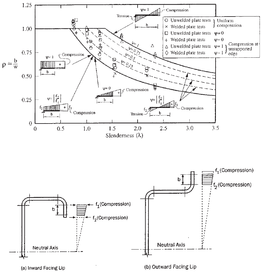
tension. According to the studies of the University of
Sydney, the effects of the stress distribution in unstiffened
elements on the effective width are shown in Fig. 3.42.
1.346
It can be seen that the effective width of an unstiffened
element increases as the stress at the supported edge
changes from compression to tension.
Subsequently, in 2004, new design provisions were added
in Section B 3.2 of the North American Specification for
determining the buckling coefficient k , the reduction factor
ρ, and the effective width b of the unstiffened elements and
edge stiffeners with stress gradient.
1.343
These provisions
can be used not only for unstiffened elements under a
stress gradient with both longitudinal edges in compression
but also for unstiffened elements under a stress gradient
with one longitudinal edge in compression and the other
longitudinal edge in tension. The following excerpts are
adapted from Section B3.2 of the 2007 edition of the North
American Specification:
B3.2 Unstiffened Elements and Edge Stiffeners with
Stress Gradient
The following notation shall apply in Section B3.2 of the
specification:
b = effective width measured from the supported
edge, determined in accordance with
Eq. (3.41)–Eq. (3.44) with f equal to f
1
and
with k and ρ being determined in accordance with
this section
b
0
= overall width of unstiffened element of unstiffened
C-section member as defined in Fig. 3.45
80 3 STRENGTH OF THIN ELEMENTS AND DESIGN CRITERIA
Figure 3.42 Reduction factor ρ vs. slenderness factor λ for unstiffened elements with stress
gradient.
1.346
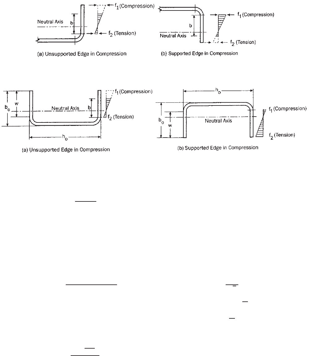
Figure 3.43 Unstiffened elements under stress gradient, both longitudinal edge in
compression.
1.345
f
1
, f
2
= stresses shown in Figs. 3.43, 3.44, and 3.45
calculated on the basis of the gross section, where
f
1
and f
2
are both compression, f
1
≥ f
2
h
0
= overall depth of unstiffened C-section member as
defined in Fig. 3.45
k = plate buckling coefficient defined in this section or,
otherwise, as defined in Section 3.5.1.1
t = thickness of element
w = flat width of unstiffened element, where w/t ≤ 60
ψ =|f
2
/f
1
| (absolute value) (3.63)
λ = slenderness factor defined in Section 3.5.1.1 with
f = f
1
ρ = reduction factor defined in this section or,
otherwise, as defined in Section 3.5.1.1
(a) Strength Determination. The effective width, b,ofan
unstiffened element under stress gradient shall be determined
in accordance with Section 3.5.1.1 with f equal to f
1
and the
plate buckling coefficient, k , determined in accordance with
Section B3.2 of the specification, unless otherwise noted. For
the cases where f
1
is in compression and f
2
is in tension,
ρ in Section 3.5.1.1 shall be determined in accordance with
this section.
1. When both f
1
and f
2
are in compression (Fig. 3.43), the
plate buckling coefficient shall be calculated in accordance
STRUCTURAL BEHAVIOR OF COMPRESSION ELEMENTS AND DESIGN CRITERIA 81
Figure 3.44 Unstiffened elements under stress gradient, one longitudinal edge in compression
and the other longitudinal edge in tension.
1.345
Figure 3.45 Unstiffened elements of C -section under stress gradient for alternative methods.
1.345
with either Eq. 3.64 or Eq. 3.65 as follows: If the stress
decreases toward the unsupported edge (Fig. 3.43a),
k =
0.578
ψ +0.34
(3.64)
If the stress increases toward the unsupported edge
(Fig. 3.43b),
k = 0.57 − 0.21ψ + 0.07ψ
2
(3.65)
2. When f
1
is in compression and f
2
in tension (Fig. 3.44),
the reduction factor and plate buckling coefficient shall be
calculated as follows:
i. If the unsupported edge is in compression (Fig. 3.44a):
ρ =
⎧
⎪
⎪
⎨
⎪
⎪
⎩
1whenλ ≤ 0.673(1 + ψ)
(1 + ψ)
{
1 − [0.22(1 +ψ)]/λ
}
λ
when λ>0.673(1 +ψ)
(3.66)
k = 0.57 + 0.21ψ + 0.07ψ
2
(3.67)
ii. If the supported edge is in compression (Fig. 3.44b),
for ψ<1
ρ =
⎧
⎪
⎪
⎪
⎪
⎨
⎪
⎪
⎪
⎪
⎩
1whenλ ≤ 0.673
(1 − ψ)
1 −
0.22
λ
λ
+ ψ
when λ>0.673
(3.68)
k = 1.70 + 5ψ + 17.1ψ
2
(3.69)
and for ψ ≥ 1
ρ = 1
The effective width, b, of the unstiffened elements of
an unstiffened C-section member shall be permitted t o
be determined using the following alternative methods, as
applicable:
1. Alternative 1 for unstiffened C-sections: When the unsup-
ported edge is in compression and the supported edge is in
tension (Fig. 3.45a),
b =
w when λ ≤ 0.856 (3.70)
ρw when λ>0.856 (3.71)
where
ρ =
0.925
√
λ
(3.72)
k = 0.145
b
0
h
0
+ 1.256 (3.73)
0.1 ≤
b
0
h
0
≤ 1.0
2. Alternative 2 for unstiffened C-sections: When the
supported edge is in compression and the unsupported edge
is in tension (Fig. 3.45b), the effective width is determined
in accordance with Section 3.5.1.2.
In calculating the effective section modulus S
e
in Section
4.2.2 or S
c
in Section 4.2.3.3, the extreme compression fiber in
Figs. 3.43b,3.44a, and 3.45a shall be taken as the edge of the
effective section closer to the unsupported edge. In calculating
82 3 STRENGTH OF THIN ELEMENTS AND DESIGN CRITERIA
the effective section modulus S
e
in Section 4.2.2, the extreme
tension fiber in Figs. 3.44b and 3.45b shall be taken as the
edge of the effective section closer to the unsupported edge.
(b) Serviceability Determination. The effective width b
d
used
in determining serviceability shall be calculated in accordance
with specification Section B3.2(a), except that f
d1
and f
d2
are
substituted for f
1
and f
2
as shown in Figs. 3.43, 3.44, and 3.45,
respectively, based on the gross section at the load for which
serviceability is determined.
The applications of the above design provisions are
illustrated in Examples 3.7 and 4.2.
3.5.3 Uniformly Compressed Elements with Stiffeners
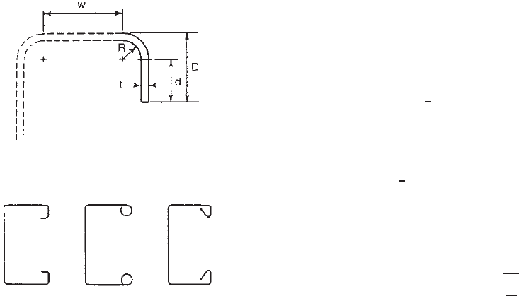
3.5.3.1 Uniformly Compressed E lements with a Simple
Lip Edge Stiffener An edge stiffener is used to provide
a c ontinuous support along a longitudinal edge of the
compression flange to improve the buckling s tress. Even
though in most cases the edge stiffener takes the form
of a simple lip (Fig. 3.46), other types of stiffeners, as
shown in Fig. 3.47, can also be used for cold-formed steel
members.
3.78,3.173
In order to provide the necessary support for the compres-
sion element, the edge stiffener must possess sufficient
rigidity. Otherwise it may buckle or displace perpendicular
to the plane of the element to be stiffened.
Both theoretical and experimental investigations on the
local stability of flanges stiffened by lips and bulbs have
been conducted in the past.
3.75–3.82,3.217–3.220
The design
requirements included in the 1986 and 1996 editions of the
AISI Specification for uniformly compressed elements with
Figure 3.46 Edge stiffener.
Figure 3.47 Edge stiffeners other than simple lip.
3.78
an edge stiffener are based on the analytical and exper-
imental investigations on adequately stiffened elements,
partially stiffened elements, and unstiffened elements
conducted by Desmond, Pekoz, and Winter
3.75,3.76
with
additional studies carried out by Pekoz and Cohen.
3.17
Those design provisions were developed on the basis of
the critical buckling criterion and the ultimate-strength
criterion. In this design approach, the design requirements
recognize that the needed stiffener rigidity depends on
the width-to-thickness ratio of the plate element being
stiffened. The interaction between the plate element and the
edge stiffener is compensated for in the design equations
for the plate buckling coefficient, the reduced effective
width of a simple lip edge stiffener, and the reduced area
of other stiffened shapes. Because a discontinuity exists
in the 1996 AISI design provisions, in 2001, Dinovitzer’s
expressions were adopted in the first edition of the North
American Specification for determining the constant “n”
to eliminate the discontinuity.
3.221
In 2007, the design provisions of the first edition of
the North American Specification were revised to limit the
design equations for applying only to simple lip edge stiff-
eners due to the fact that previous equations for complex
lip stiffeners were found to be unconservative, in compar-
ison with the nonlinear finite-element analysis conducted
by Schafer, Sarawit, and Pekoz.
3.222
According to Section B4 of the 2007 edition of the
North American Specification, the effective width of the
uniformly compressed elements with a simple lip edge
stiffener can be calculated by the following equations.
For other stiffener shapes, the design of member strength
may be handled by the direct-strength method provided in
Appendix 1 of the North American Specification:
(a) Strength Determination. For w/t ≤ 0.328S
I
a
= 0 (no edge stiffener needed) (3.74)
b = w (3.75)
b
1
= b
2
=
1
2
w (see Figure 3.48) (3.76)
d
s
= d
s
For w/t > 0.328 S
b
1
=
1
2
(b)(R
I
) (see Figure3.48) (3.77)
b
2
= b − b
1
(see Figure 3.48) (3.78)
d
s
= d
s
(R
I
) (3.79)
where
S = 1.28
E
f
(3.80)
STRUCTURAL BEHAVIOR OF COMPRESSION ELEMENTS AND DESIGN CRITERIA 83
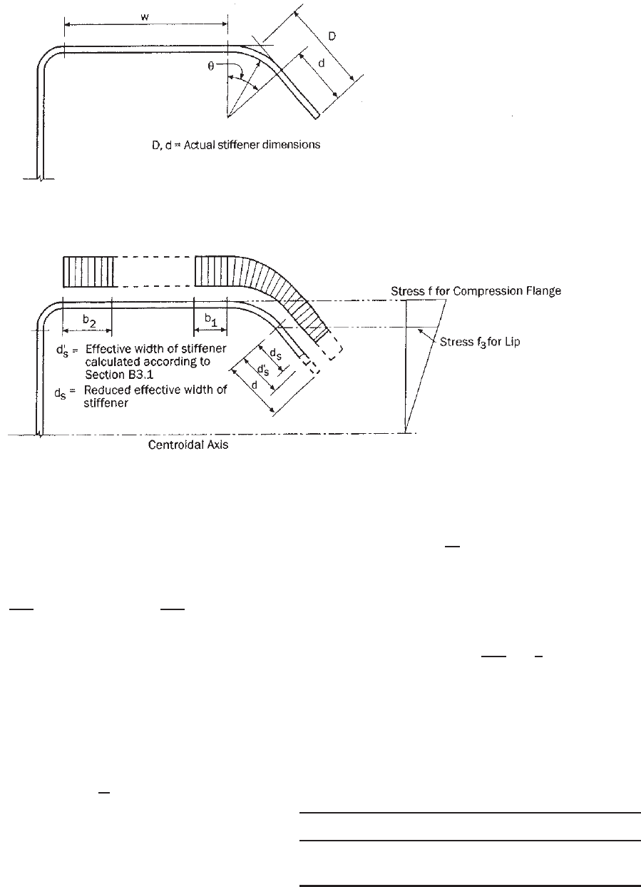
Figure 3.48 Elements with simple lip edge stiffener.
1.345
w is the flat dimension defined in Fig. 3.48; t is the
thickness of the section; I
a
, the adequate moment of inertia
of the stiffener so that each component element will behave
as a stiffened element, is defined as
I
a
= 399t
4
w/t
S
− 0.328
3
≤ t
4
115
w/t
S
+ 5
(3.81)
b is the effective design width; b
1
, b
2
are the portions
of effective design width as defined in Fig. 3.48; d
s
is
the reduced effective width of the stiffener as defined
in Fig. 3.48 and used in computing overall effective
sectional properties; d
s
is the effective width of the stiff-
ener calculated in accordance with Section 3.5.2.2 (see
Fig. 3.48); and
(R
I
) =
I
s
I
a
≤ 1 (3.82)
where I
s
is the moment of inertia of the full section
of stiffener about its own centroidal axis parallel to the
element to be stiffened. For edge stiffeners, the round corner
between the stiffener and element to be stiffened is not
considered as a part of the stiffener:
I
s
=
1
12
(d
3
t sin
2
θ) (3.83)
See Fig. 3.48 for definitions of other dimensional variables.
The effective width b in Eqs. (3.77) and (3.78) shall be
calculated in accordance with Section 3.5.1.1 with the plate
buckling coefficient k as given in Table 3.5, where
n =
0.582 −
w/t
4S
≥
1
3
(3.84)
(b) Serviceability Determination. The effective width b
d
used in determining serviceability shall be calculated as
in item (a), except that f
d
is substituted for f, where f
d
is
Table 3.5 Determination of Plate Buckling
Coefficient k
Simple Lip Edge Stiffener (140
◦
≥θ ≥40
◦
)
D/w ≤ 0.25 0.25 < D/w ≤ 0.8
3.57 (R
I
)
n
+ 0.43 ≤ 4 (4.82 – 5D/w)(R
I
)
n
+ 0.43 ≤ 4
84 3 STRENGTH OF THIN ELEMENTS AND DESIGN CRITERIA
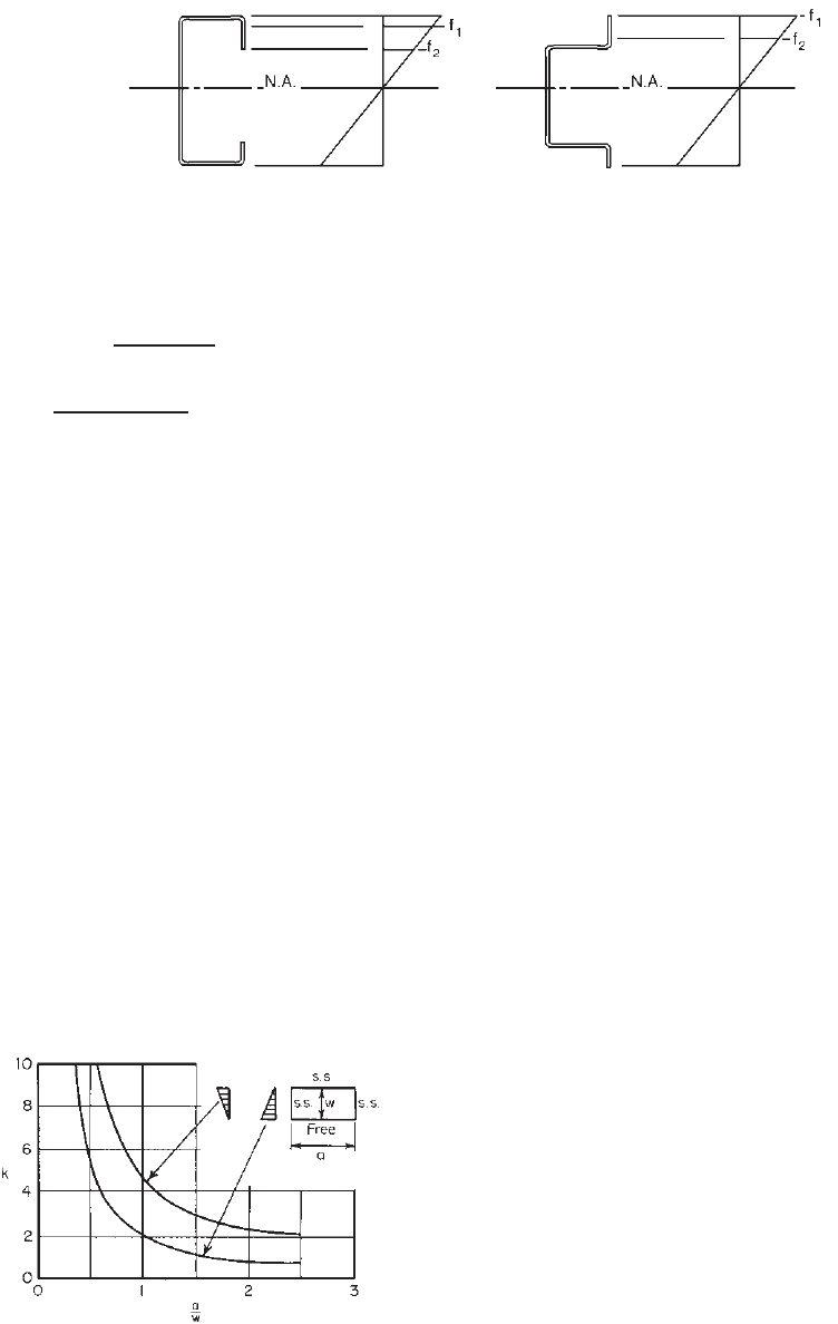
Figure 3.49 Stress distribution in edge-stiffened flange.
3.17
the computed compressive stress in the effective section at
the load for which serviceability is determined.
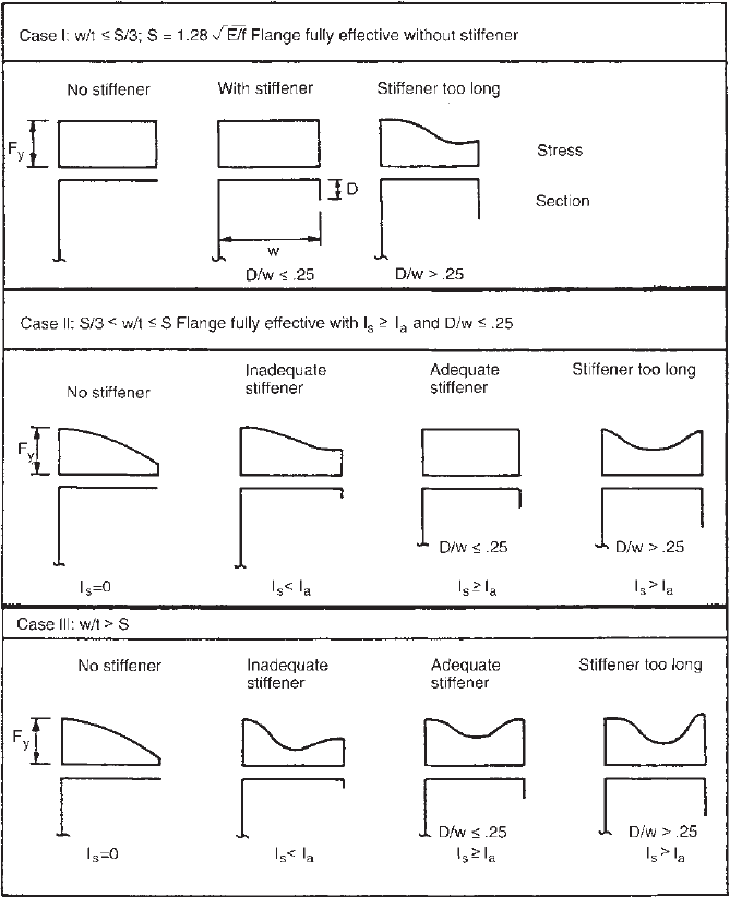
According to Ref. 3.17, the distribution of longitudinal
stresses in a compression flange with an edge stiffener is
shown in Fig. 3.49 for three cases.
The design criteria are intended to account for the
inability of the edge stiffener to prevent distortional buck-
ling by reducing the local buckling coefficient k for
calculating the effective design width of the compression
element. Because the empirical equations were derived on
the basis of the tests of back-to-back sections with strong
restraint against web buckling, past research demonstrated
that these AISI design equations may provide unconser-
vative strength predictions for laterally braced beams and
columns with edge-stiffened flanges when the distortional
buckling mode of the compression flange is critical.
3.168
Additional discussions of distortional buckling are given in
Section 4.2.4 for beams and Section 5.6 for columns.
Recent compression tests c onducted by Young and
Hancock on channels with inclined simple edge stiffeners
using a yield stress of 450 MPa (65.3 ksi or 4588 kg/cm
2
)
indicated that the design strength predicted by the North
American Specification are conservative for all channels
with outward and inward edge stiffeners, when the flange
w/t ratios are between 20 and 30, but are slightly
unconservative for channels with the flange w/t ratios
between 40 and 50, except for channels with inward
edge stiffeners.
3.219
For channels having flange w/t ratio