Yu W., LaBoube R.A. Cold-Formed Steel Design
Подождите немного. Документ загружается.

STRUCTURAL BEHAVIOR OF COMPRESSION ELEMENTS AND DESIGN CRITERIA 85
of 65, the North American specification predicts unconser-
vative results.
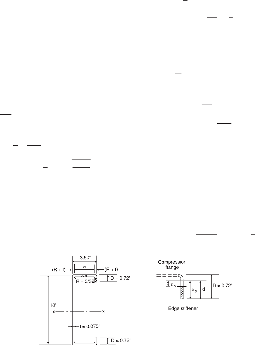
Example 3.7 Compute the effective width of the
compression flange of the channel section with an edge
stiffener as shown in Fig. 3.50. Assume that the channel
is used as a beam and that lateral bracing is adequately
provided. Use F
y
= 33 ksi. Also compute the reduced
effective width of the edge stiffener.
SOLUTION
1. Effective Width of Compression Flange. Because the
compression flange is uniformly compressed element with
an edge stiffener, its effective width should be determined
according to Eqs. (3.74)–(3.84).
As the first step, the flat width w, w/t ratio, and S =
1.28
√
E/f are computed as follows:
w = 3.5 − 2(R + t) = 3.163 in.
w
t
=
3.163
0.075
= 42.17
S = 1.28
E
f
= 1.28
29,500
33
= 38.27
0.328S = 0.328(38.27) = 12.55
Since w/t > 0.328S, b <w, the effective width of
the compression flange can be determined by using the
following k value: For the given simple lip edge stiffener
with θ = 90
◦
and D/w = 0.72/3.163 = 0.228, which is
less than 0.25, according to Table 3.5,
k = 3.57(R
I
)
n
+ 0.43 ≤ 4
where
R
I
=
I
s
I
a
≤ 1 [Eq. (3.82)]
n =
0.582 −
w/t
4S
≥
1
3
[Eq. (3.84)]
For the simple lip edge stiffener,
d = D − (R + t) = 0.551 in.
and
I
s
=
1
12
d
3
= 1.047 × 10
−3
in.
4
[Eq. (3.83)]
Based on Eq. (3.81),
I
a
= 399t
4
w/t
S
− 0.328
3
= 399(0.075)
4
42.17
38.27
− 0.328
3
= 5.852 × 10
−3
in.
4
The above computed value should not exceed the following
value:
t
4
115
w/t
S
+ 5
= (0.075)
4
115
42.17
38.27
+ 5
= 4.168 × 10
−3
in.
4
Use I
a
= 4.168 × 10
−3
in.
4
Therefore
R
I
=
I
s
I
a
=
1.047 × 10
−3
4.168 × 10
−3
= 0.251 < 1OK
n =
0.582 −
42.17
4(38.27)
= 0.307 <
1
3
Figure 3.50 Example 3.7.
86 3 STRENGTH OF THIN ELEMENTS AND DESIGN CRITERIA
Use n = 1/3. The local buckling coefficient is
k = 3.57(0.251)
1/3
+ 0.43
= 2.68 < 4OK
Use k = 2.68 to calculate the effective width of the
compression flange by using Eqs. (3.41)–(3.44) as follows:
λ =
1.052
√
k
w
t
f
E
=
1.052
√
2.68
(
42.17
)
33
29500
= 0.906 > 0.673
The effective width of the compression flange is
b = ρw =
1 − 0.22/λ
λ
w
=
1 − 0.22/0.906
0.906
(3.163)
= 2.643 in.
Based on Eqs. (3.77) and (3.78), the effective flange widths
b
1
and b
2
(Fig. 3.48) are determined as follows:
b
1
=
b
2
(R
I
)
=
2.643
2
(0.251) = 0.332 in.
b
2
= b − b
1
= 2.643 − 0.332 = 2.311 in.
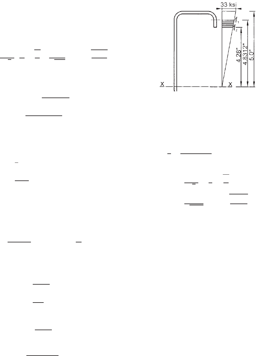
2. Reduced Effective Width of Edge Stiffener . The effec-
tive width of the edge stiffener under a gradient can
be determined by using Section 3.5.2.2. According to
Eq. (3.64),
k =
0.578
ψ +0.34
where ψ =
f
2
f
1
In the above equation, the compressive stresses f
1
and f
2
as shown in Fig. 3.51 are calculated on the basis of the
gross section as follows:
f
1
= 33
4.8312
5.0
= 31.886 ksi
f
2
= 33
4.28
5.0
= 28.248 ksi
Therefore,
ψ =
28.248
31.886
= 0.886
and
k =
0.578
0.886 + 0.34
= 0.471
The k value of 0.471 calculated above for the edge
stiffener under a stress gradient is slightly larger than the
Figure 3.51 Stress distribution in edge stiffener.
k value of 0.43 for unstiffened elements under uniform
compression.
The effective width of the edge stiffener can be deter-
mined as follows:
d
t
=
D − (R + t)
t
= 7.35
f = f
1
= 31.886 ksi
λ =
1.052
√
k
d
t
f
E
=
1.052
√
0.471
(7.35)
31.886
29,500
= 0.370 < 0.673
ρ = 1.0
The effective width of the edge stiffener a s shown in
Fig. 3.50 is
d
s
= d = 0.551 in.
The reduced effective width of the edge stiffener is
d
s
= d
s
(R
I
) = 0.551(0.251) = 0.138 in.
3.5.3.2 Uniformly Compressed Elements with Interme-
diate Stiffeners
3.5.3.2.1 Uniformly Compressed Elements with Single
Intermediate Stiffener In the design of cold-formed steel
beams, when the width-to-thickness ratio of the stiffened
compression flange is relatively large, the structural effi-
ciency of the section can be improved by adding an inter-
mediate stiffener as shown in Fig. 3.52.
The buckling behavior of rectangular plates with central
stiffeners is discussed in Ref. 3.7. The load-carrying
capacity of an element with a longitudinal intermediate
STRUCTURAL BEHAVIOR OF COMPRESSION ELEMENTS AND DESIGN CRITERIA 87
Figure 3.52 Section with single i ntermediate stiffener.
stiffener has been studied by H
¨
oglund,
3.72
K
¨
onig,
3.73
K
¨
onig
and Thomasson,
3.74
Desmond, Pekoz, and Winter,
3.75–3.77
Pekoz,
3.17
and Yang and Schafer.
3.223
In the study of Bernard, Bridge, and Hancock,
3.171,3.172
both local buckling and distortional buckling in the
compression flange of profiled steel decks were discussed
by the researchers.
As far as the design provisions are concerned, the 1980
and earlier editions of the AISI Specification included the
requirements for the minimum moment of inertia of the
intermediate stiffener for multiple-stiffened compression
elements. When the size of the actual intermediate stiffener
did not satisfy the required minimum moment of inertia, the
load-carrying capacity of the member had to be determined
either on the basis of a flat element disregarding the
intermediate stiffener or through tests. For some cases, this
approach could be unduly conservative.
3.17
The AISI design provisions were revised in 1986 on the
basis of the research findings reported in Refs. 3.75–3.77.
In that method, the buckling coefficient k for determining
the effective width of subelements and the reduced area of
the stiffener was calculated by using the ratio I
s
/I
a
, where
I
s
is the actual stiffener moment of inertia and I
a
is the
adequate moment of inertia of the stiffener determined from
the applicable equations. The same design requirements
were retained in the 1996 edition of the AISI Specification.
Because a discontinuity could occur in those equations,
the design provisions were revised in the 2001 edition of
the North American Specification by adopting Dinovitzer’s
expressions to eliminate the discontinuity.
3.221
In the 2007 edition of the North American Specification,
the design of uniformly compressed stiffened elements with
a single intermediate stiffener was merged with the stiffened
elements having multiple intermediate stiffeners. Section
3.5.3.2.2 provides the AISI design requirements for this
particular case by using the number of stiffeners equal to
unity (i.e., n = 1) in Eqs. (3.92) and (3.93). See Example
4.4 for the application of these equations.
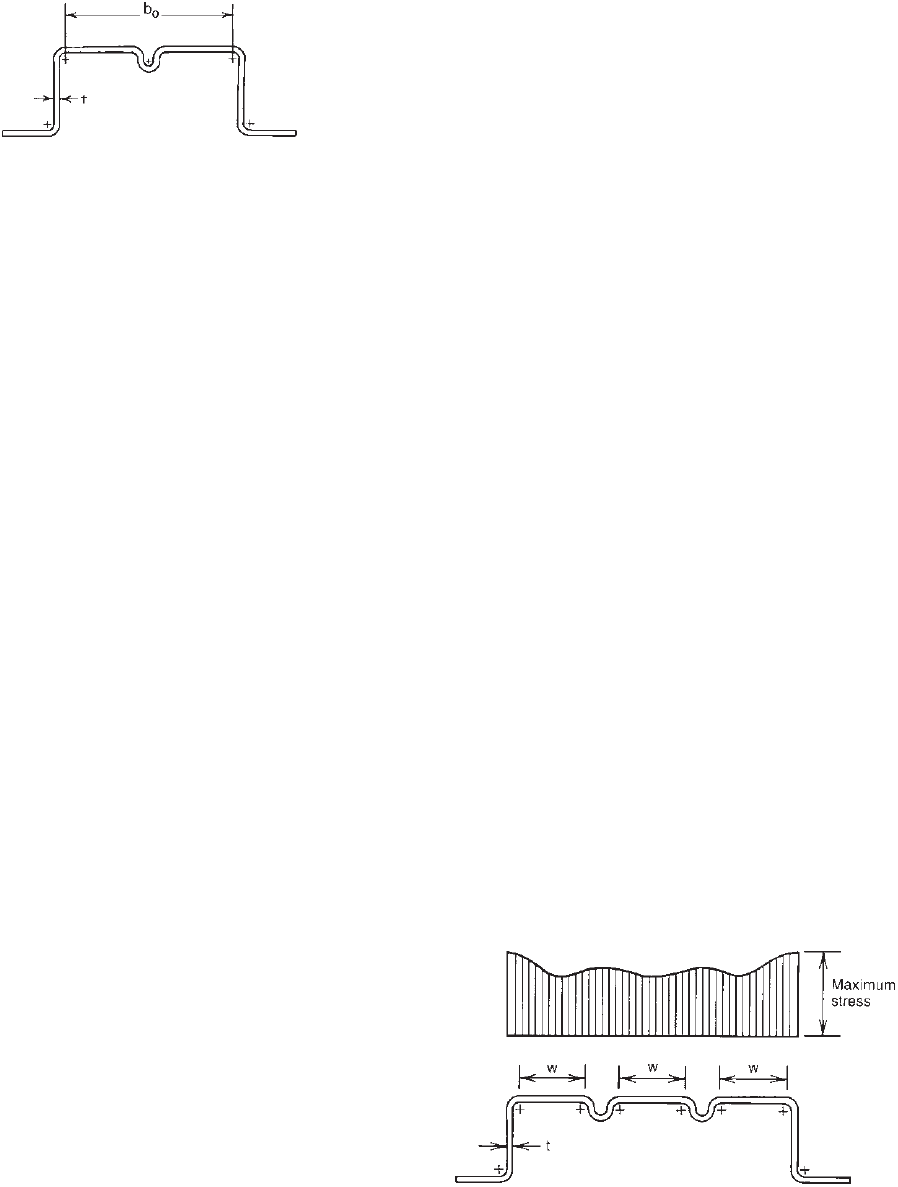
3.5.3.2.2 Uniformly Compressed Elements with
Multiple Intermediate Stiffeners In beam sections, the
normal stresses in the flanges result from shear stresses
between the web and flange. The web generates the normal
stresses by means of the shear stress which transfers to the
flange. The more remote portions of the flange obtain their
normal stress through shear from those close to the web.
For this reason there is a difference between webs and
intermediate stiffeners. The latter is not a shear-resisting
element and does not generate normal stresses through
shear. Any normal stress in the intermediate stiffener
must be transferred to it from the web or webs through
the flange portions. As long as the subelement between
web and stiffener is flat or is only very slightly buckled,
this stress transfer proceeds in an unaffected manner.
In this case the stress in the stiffener equals that at
the web, and the subelement is as effective as a regular
single-stiffened element with the same w/t ratio. H owever,
for subelements having larger w/t ratios, the slight waves
of the subelement interfere with complete shear transfer
and create a “shear lag” problem which results in a stress
distribution as shown in Fig. 3.53.
As far as the design is concerned, the AISI design
provisions for uniformly compressed elements with one
intermediate stiffener were revised in 1986 on the basis
of the 1981 Cornell research.
3.75–3.77
Because this Cornell
project did not cover the multiple-stiffened elements with
more than one intermediate stiffener a nd the edge-stiffened
elements with intermediate stiffeners, the 1986 and 1996
editions of the AISI Specification a dopted the same design
provisions as the 1980 edition of the AISI Specification for
these cases.
In the 1996 edition of the AISI Specification, the
design requirements for uniformly compressed elements
with multiple intermediate stiffeners and edge-stiffened
elements with intermediate stiffeners included (a) the
minimum moment of inertia of the full stiffener about its
own centroidal axis parallel to the element to be stiffened,
(b) the number of stiffeners considered to be effective,
(c) the “equivalent element” of the entire multiple-stiffened
element for closely spaced stiffeners with an “equivalent
thickness,” (d) the reduced effective width of subelement
Figure 3.53 Stress distribution in compression flange with
intermediate stiffeners.
1.161
88 3 STRENGTH OF THIN ELEMENTS AND DESIGN CRITERIA
having w/t > 60, and (e) the reduced effective stiffener
area when the w/t ratio of the subelement exceeds 60. The
reasons for using the above requirements are discussed by
Yu in Ref. 1.354.
In the past, the structural behavior and strength
of cold-formed steel members with multiple longitu-
dinal intermediate stiffeners have been investigated by
Papazian, Schuster, and Sommerstein,
3.174
Schafer and
Pekoz,
3.175,3.176
Acharya and Schuster,
3.177,3.178
Teter and
Kolakowski,
3.224
and Schafer.
3.225
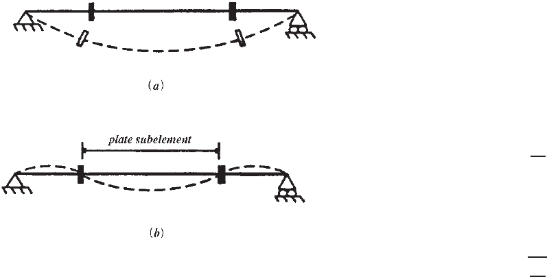
Some of these studies
considered the distortional buckling of the entire stiffened
elements as a unit (Fig. 3.54a) and local buckling of
the subelements between stiffeners (Fig. 3.54b). The
AISI Specification and the Canadian Standard have been
compared with analytical and experimental results. It
has been found that the 1996 AISI design requirements
were nearly 20% unconservative for the 94 members
studied.
3.175,3.176
Based on the experimental and numerical
studies, a method for calculating the ultimate strength of
stiffened elements with multiple intermediate stiffeners
was proposed by Schafer and Pekoz in Ref. 3.176. This
method involves the calculation of the critical local
buckling stress for the subelement and the distortional
buckling stress for the entire multiple-stiffened element.
Because the experimental and numerical data revealed that
the overall (distortional) buckling mode usually dominated
the behavior, a modified effective width equation was
proposed for the entire multiple-stiffened element by using
the proposed plate buckling coefficient to determine the
reduction factor.
Consequently, in 2001, the design provisions were
revised to reflect those additional research findings.
1.336,3.176
Figure 3.54 Buckling modes of multiple-stiffened elements with
longitudinal intermediate stiffeners
3.176
:(a) distortional buckling
mode; (b) local buckling mode.
The same requirements are retained in Section B5.1 of
the 2007 edition of the North American Specification for
determining the effective width of uniformly compressed
stiffened elements w ith single or multiple intermediate
stiffeners as given below:
B5.1 Effective Widths of Uniformly Compressed
Stiffened Elements with Single or Multiple
Intermediate Stiffeners
The following notation shall apply as used in this section.
A
g
= gross area of element including stiffeners
A
s
= gross area o f stiffener
b
e
= effective width of element, located at centroid of
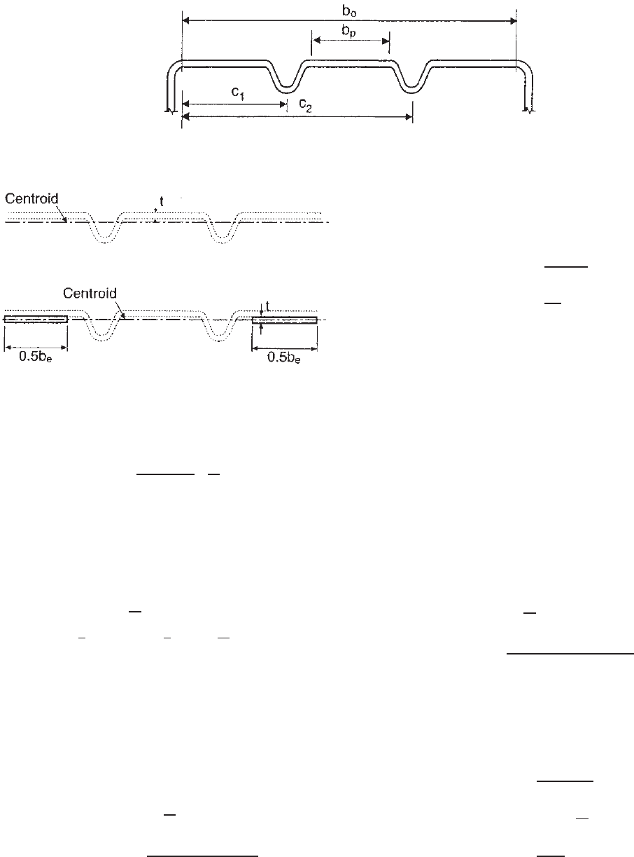
element including stiffeners; see Fig. 3.56
b
o
= total flat width of stiffened element; see Fig. 3.55
b
p
= largest subelement flat width; see Fig. 3.55
c
i
= horizontal distance from edge of element to
centerline(s) of stiffener(s); see Fig. 3.55
F
cr
= plate elastic buckling stress
f = uniform compressive stress acting on flat el ement
h = width of elements adjoining stiffened element (e.g.,
depth of web in hat section with multiple
intermediate stiffeners in compression flange is equal
to h; if adjoining elements have different widths, use
smallest one)
I
sp
= moment of inertia of stiffener about centerline of flat
portion of element; radii that connect the stiffener to
the flat can be included
K = plate buckling coefficient of element
k
d
= plate buckling coefficient for distortional buckling
k
loc
= plate buckling coefficient for local subelement
buckling
L
br
= unsupported length between brace points or other
restraints which restrict distortional buckling of
element
R = modification factor for distortional plate buckling
coefficient
n = number of stiffeners in element
t = element thickness
I = Index for stiffener “i ”
λ = slenderness factor
ρ = reduction factor
The effective width shall be calculated in accordance with
Eq. ( 3.85) as follows:
b
e
= ρ
A
g
t
(3.85)
where
ρ =
1whenλ ≤ 0.673
(1 − 0.22/λ)/λ when λ>0.673
(3.86)
where
λ =
f
F
cr
(3.87)
STRUCTURAL BEHAVIOR OF COMPRESSION ELEMENTS AND DESIGN CRITERIA 89
Figure 3.55 Plate widths and stiffener locations.
1.345
Figure 3.56 Effective width locations.
1.345
where
F
cr
= k
π
2
E
12(1 − μ
2
)
t
b
o
2
(3.88)
The plate buckling coefficient, k, shall be determined from
the minimum of Rk
d
and k
loc
, as determined in accordance
with Section B5.1.1 or B5.1.2, as applicable:
k = minimum of Rk
d
and k
loc
(3.89)
R =
⎧
⎪
⎨
⎪
⎩
2when
b
o
h
< 1
1
5
(11 − b
o
/
h) ≥
1
2
when
b
o
h
≥ 1
(3.90)
B5.1.1 Specific Case: Single or n Identical Stiffeners,
Equally Spaced
For uniformly compressed elements with single, or multiple
identical and equally spaced stiffeners, the plate buckling
coefficients and effective widths shall be calculated as follows:
(a) Strength Determination
3.240
k
loc
= 4
b
o
b
p
2
(3.91)
k
d
=
(1 + β
2
)
2
+ γ(1 + n)
β
2
[1 + δ(n +1)]
(3.92)
where
β = [1 + γ(n+1)]
1
/
4
(3.93)
where
γ =
10.92I
sp
b
o
t
3
(3.94)
δ =
A
s
b
o
t
(3.95)
If L
br
<βb
o
, L
br
/b
o
shall be permitted to be substituted
for β to account for increased capacity due to bracing.
(b) Serviceability Determination. The effective width, b
d
,used
in determining serviceability shall be calculated as in
Section B5.1.1(a), except that f
d
is substituted for f, where
f
d
is the computed compressive stress in the element being
considered based on the effective section at the load for
which serviceability is determined.
B5.1.2 General Case: Arbitrary Stiffener Size,
Location, and Number
For uniformly compressed stiffened elements with stiffeners
of arbitrary size, location, and number, the plate buckling
coefficients and effective widths shall be calculated as follows:
(a) Strength Determination
k
loc
= 4
b
o
b
p
2
(3.96)
k
d
=
(1 + β
2
)
2
+ 2
n
i=1
γ
i
ω
i
β
2
1 + 2
n
i=1
δ
i
ω
i
(3.97)
where
β =
2
n
i=1
γ
i
ω
i
+ 1
1
/
4
(3.98)
where
γ
i
=
10.92(I
sp
)
i
b
o
t
3
(3.99)
ω
i
= sin
2
π
c
i
b
o
(3.100)
δ
i
=
(A
s
)
i
b
o
t
(3.101)
90 3 STRENGTH OF THIN ELEMENTS AND DESIGN CRITERIA
If L
br
<βb
o
, L
br
/b
o
shall be permitted to be substituted
for β to account for i ncreased capacity due to bracing.
(b) Serviceability Determination. The effective width, b
d
,used
in determining serviceability shall be calculated as in
Section B5.1.2(a), except that f
d
is substituted for f, where
f
d
is the computed compressive stress in the element being
considered based on the effective section at the load for
which serviceability is determined.
It should be noted that according to Eq. (3.85), the effective
width of the uniformly compressed stiffened elements with
multiple intermediate stiffeners is determined from an overall
equivalent flat width (A
g
/t), in which A
g
is the gross area of
the stiffened element including intermediate stiffeners. The
equation used for computing the reduction factor, ρ,isthe
same as Eq. (3.43), except that in the calculation of slenderness
factor λ, the plate buckling coefficient, k, is the lesser of Rk
d
and k
loc
, and the width-to-thickness ratio is based on b
o
/t,
in which b
o
is the total overall flat width of the stiffened
element. See Fig. 3.55. As shown in Fig. 3.56, the effective
width is placed at the centroidal line of the entire element
including the stiffeners for the calculation of the effective
sectional properties.
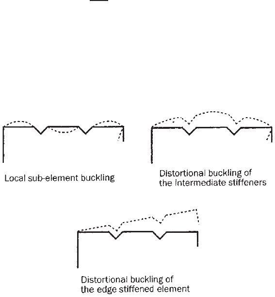
3.5.3.2.3 Edge-Stiffened Elements with Intermediate
Stiffeners For the design of edge-stiffened elements with
intermediate stiffeners, if the overall flat width-to-thickness
ratio (b
o
/t)issmall(i.e.,b
o
/t ≤ (0.328S = 0.42
√
E/f ) the
flat subelements and intermediate stiffeners can be fully
effective. However, if the b
o
/t ratio is large, three buckling
modes are possible, as shown in Fig. 3.57.
1.346,3.226
In order to provide new requirements for computing the
effective width of edge-stiffened elements with intermediate
stiffeners, Section B5.2 of the North American specification
includes the following new design provisions
1.345
:
B5.2 Edge-Stiffened Elements with Intermediate
Stiffener(s)
(a) Strength Determination. For edge-stiffened elements with
intermediate stiffener(s), the effective width, b
e
, shall be
determined as follows:
•
If b
o
/t ≤ 0.328S, the element is fully effective and no
local buckling reduction is required.
•
If b
o
/t ≥ 0.328S, then the plate buckling coefficient, k ,
is determined in accordance with Section 3.5.3.1, but
with b
o
replacing w in all expressions.
•
If k calculated from Section 3.5.3.1 is less than 4.0
(k < 4), the intermediate stiffener(s) is ignored and the
provisions of Sect ion 3.5.3.1 are followed for calculation
of the effective width.
•
If k calculated from Section 3.5.3.1 is equal to 4.0
(k = 4), the effective width of the edge-stiffened element
is calculated from the provisions of Section 3.5.3.2.2,
with the following exception: R calculated in accordance
with Section 3.5.3.2.2 is less than or equal to 1, where
b
o
= total flat width of edge-stiffened element
See Sections 3.5.3.1 and 3.5.3.2.2 for definitions of other
variables.
(b) Serviceability Determination. The effective width, b
d
, used
in determining serviceability shall be calculated as in (a)
above, except t hat f
d
is substituted for f, where f
d
, is
the computed compressive stress in the element being
considered based on the effective section at the load for
which serviceability is determined.
In the above criteria, the modification factor (R)forthe
distortional plate buckling coefficient is limited to less than
or equal to 1.0 due to the fact that the edge-stiffened element
does not have the same web rotational restraint along the side-
supported edge stiffener.
Figure 3.57 Buckling modes in an edge-stiffened element with intermediate stiffeners.
1.345
PERFORATED ELEMENTS AND MEMBERS 91
For t he calculation of effective sectional properties, the
effective width (b
e
) of the edge-stiffened element with inter-
mediate stiffeners is placed at the centroidal line as shown in
Fig. 3.56. The centroidal line is located on the basis of the
gross areas of subelements and intermediate stiffeners without
using the edge stiffener.
The adequacy of this approach was demonstrated by the
stub compression tests performed by Yang and Hancock in
2003.
3.219
3.6 PERFORATED ELEMENTS AND MEMBERS
In cold-formed steel structural members, holes are some-
times provided in webs and/or flanges of beams and
columns for duct work, piping, bracing, and other construc-
tion purposes, as shown in Fig. 1.3. For steel storage racks
(Fig. 1.10), various types of holes are often used for the
purpose of easy assembly. The presence of such holes may
result in a reduction of the strength of individual compo-
nent elements and of the overall strength of the member
depending on the size, shape, and arrangement of holes,
the geometric configuration of the cross section, and the
mechanical properties of the material used.
The exact analysis and the design of steel sections having
perforated elements are complex, in particular when the
shapes and the arrangement of the holes are unusual.
Even though limited information is a vailable for rela-
tively thick steel sections,
1.148,1.165,3.84–3.86
on the basis of
previous investigations,
3.87–3.90
these design criteria may
not be completely applicable to perforated cold-formed steel
sections due to the fact that local buckling is usually a major
concern for thin-walled structural members.
For perforated cold-formed steel structural members the
load-carrying capacity of the member is usually governed
by the buckling behavior and the postbuckling strength
of the component elements. The critical buckling loads
for perforated plates and members have been studied
by numerous investigators.
3.91–3.111,3.227–3.233
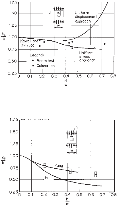
The effect of
circular holes on the buckling coefficients in compres-
sion is shown in Fig. 3.58. Figure 3.59 shows the effect
of a central square hole on the buckling coefficient for
a simply supported square plate, in which the top curve
was computed by the finite-element method developed
by Yang.
3.112
The test data obtained from the testing
of beams and columns are also shown in these two
figures.
3.99
In Figs. 3.58 and 3.59, k is the buckling coefficient for
square plates without holes, k
c
is the buckling coefficient
for perforated square plates having a circular hole, k
s
is
the buckling coefficient for perforated square plates having
a square hole, d is the diameter of circular holes, h is
the width of square holes, and w is the width of the
plate.
Figure 3.58 Effect of circular hole on buckling coefficient in
compression.
3.99
Figure 3.59 Effect of square hole on buckling coefficient in
compression.
3.99
The postbuckling strength of perforated compression
elements has also been studied by Davis and Yu in
Ref. 3.99. It was found that Winter’s effective width
equation for a solid plate [Eq. (3.35)] can be modified
for the determination of the effective width of perforated
stiffened elements. Even though the buckling load for the
perforated stiffened element is affected more by square
holes than by circular holes, the postbuckling strength of
the elements with square and circular holes was found to
be nearly the same if the diameter of a circular hole was
the same as the width of a square hole.
The effect of perforations on the design of industrial steel
storage racks has been accounted for by using net section
properties determined by s tub column tests.
1.165
Considering the effect of holes on the shear buckling of
a s quare plate, the reduction of the buckling coefficients
has been studied by Kroll,
3.113
Rockey, Anderson, and
Cheung,
3.114,3.115
and Narayanan and Avanessian.
3.101
92 3 STRENGTH OF THIN ELEMENTS AND DESIGN CRITERIA
Figure 3.60 Effect of circular hole on buckling coefficient in
shear.
3.114
Figure 3.60 shows the buckling coefficients in shear
affected by holes.
During recent years, extensive studies of perforated
elements and members have been conducted by numerous
investigators. See Refs. 3.228–3.232, 3.242–3.248, 3.250,
and 3.251. It is expected that new design provisions for
perforated members will soon be developed on the basis of
recent research findings.
3.6.1 Uniformly Compressed Stiffened Elements with
Circular Holes
Based on the Cornell study presented in Ref. 3.100, limited
design provisions have been included in the AISI spec-
ification since 1986. Section B2.2 of the North Amer-
ican specification
1.345
includes the following provisions for
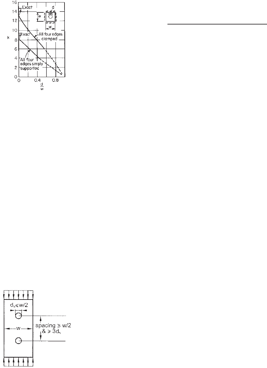
determining the effective width of uniformly compressed
stiffened elements with circular holes (Fig. 3.61):
(a) Strength Determination. The effective width, b, shall be
calculated by either Eq. (3.102) or Eq. (3.103) as follows:
For 0.50 ≥ d
h
/w ≥ 0, w/t ≤ 70, and the distance between
Figure 3.61 Uniformly compressed stiffened elements with
circular holes.
centers of holes ≥0.50w and ≥3d
h
,
b =
⎧
⎪
⎪
⎪
⎨
⎪
⎪
⎪
⎩
w − d
h
when λ ≤ 0 .673 (3.102)
w
1 − 0.22/λ − 0.8d
h
/w + 0.085d
h
/(λw)
λ
when λ>0.673 (3.103)
In all cases,
b ≤ w − d
h
where w = flat width
t = thickness of element
d
h
= diameter of holes
λ = as defined in Section 3.5.1.1
(b) Serviceability Determination. The effective width, b
d
,used
in determining serviceability shall be equal to b calculated
in accordance with Eqs. (3.41)–(3.44) except that f
d
is
substituted for f, where f
d
is the computed compressive
stress in the element being considered.
It should be noted that Eq. (3.103) was revised in 2004
to provide continuity at λ = 0.673.
3.6.2 Uniformly Compressed Stiffened Elements
with Noncircular Holes
For uniformly compressed stiffened elements with noncir-
cular holes such as the perforated web element of steel studs
shown in Fig. 3.62, the effective width of the perforated
web can be determined by assuming the web to consist
of two uniformly compressed unstiffened elements with
the flat width one on each side of the hole. The effec-
tive design width of these unsiffened compression elements
can be calculated in accordance with Section 3.5.2.1 or the
effective area of the perforated web can be determined from
stub-column tests.
The unstiffened strip approach was studied by Miller and
Pekoz at Cornell University in the 1990s.
3.186
Test results
indicated that this method is generally conservative for the
wall studs tested in the Cornell program. This approach has
long been used in the Rack Manufacturers Institute (RMI)
Specification for the design of perforated rack columns.
1.156
Since 1996, similar requirements were used in the AISI
Specification for the design of wall studs under s pecific
limitations. The same requirements were retained in the
2001 North American Specification. In the 2007 edition
of the North American Specification, the following design
provisions were moved from the previous Section D4 to
the current Section B2.2 of the Specification for uniformly
compressed stiffened elements with noncircular holes:
(a) Strength Determination. A uniformly compressed stiffened
element with noncircular holes shall be assumed to consist of
two unstiffened strips of flat width, c, adjacent to the holes
PERFORATED ELEMENTS AND MEMBERS 93
Figure 3.62 Uniformly compressed stiffened elements with noncircular holes.
1.345
(see Fig. 3.62). The effective width, b, of each unstiffened
strip adjacent to the hole shall be determined in accordance
with Section 3.5.1.1, except that plate buckling coefficient, k ,
shall be taken as 0.43 and w as c. These provisions shall be
applicable within the following limits:
1. center-to-center hole spacing, s ≥ 24 in. (610 mm),
2. clear distance from the hole at ends, s
end
≥ 10 in. (254 mm),
3. depth of hole, d
h
≤ 2.5 in. (63.5 mm),
4. length of hole, L
h
≤ 4.5 in. (114 mm), and
5. ratio of the depth of hole, d
h
, to the out-to-out width, w
o
,
d
h
/w
o
≤ 0.5.
Alternatively, the effective width, b, shall be permitted to
be determined by stub-column tests in accordance with the test
procedure, AISI S902.
(b) Serviceability Determination. The effective width, b
d
,used
in determining serviceability shall be calculated in accordance
with Eqs. (3.45)–(3.47).
It should be noted that the effective area should be
based on the lesser of the total effective design width of
two unstiffened elements and the effective design width
determined for the stiffened element with the flat width, w.
The calculation of the effective area for the steel stud having
noncircular web perforations is illustrated in Example III-2
of the 2008 edition of the AISI Design Manual.
1.349
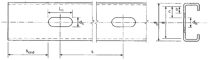
3.6.3 C-Section Webs with Holes under Stress
Gradient
In the past, numerous studies have been conducted to inves-
tigate the structural behavior and strength of perforated
elements and members subjected to tension, compression,
bending, shear, and web crippling.
3.179–3.193,3.197–3.200
Based on the research work conducted by Shan et al. at
the University of Missouri-Rolla,
3.184,3.197
the following
requirements have been included in Section B2.4 of
the specification for determining the effective depth of
C-section webs with holes under stress gradient
1.345
:
(a) Strength Determination.Whend
h
/h < 0.38, the effective
widths, b
1
and b
2
, shall be determined by Section 3 .5.1.2
by assuming no hole exists in the web. When d
h
/h > 0.38,
the effective width shall be determined by Section 3.5.2.1,
assuming the compression portion of the web consists of
an unstiffened element adjacent to the hole wi th f = f
1
,
as shown in Fig. 3.63.
(b) Serviceability Determination. Theeffectivewidthsshallbe
determined by Section 3.5.1.2 by assuming no hole exists
in the web.
Because the above requirements are based on the experi-
mental study, these provisions are applicable only within the
following limits:
1. d
h
/h < 0.7
2. h/t ≤ 200
3. Holes centered at middepth of the web
4. Clear distance between holes ≥ 18 in. (457 mm)
5. Noncircular holes, corner radii ≥ 2t
6. Noncircular holes, d
h
≤ 2.5 in. (64 mm) and L
h
≤ 4.5 in.
(114 mm)
7. Circular hole diameter ≤ 6 in. (152 mm)
8. d
h
≥ 9/16 in. (14 mm), where
d
h
= depth of web hole
h = depth of flat portion of web measured along
the plane of the web
t = thickness of web
L
h
= length of web hole
b
1
, b
2
= effective widths defined by Fig. 3.30
Although these provisions are based on the tests of
C-sections having the web hole centered at middepth of
the section, the provisions may be conservatively applied
to sections for which the full unreduced compression region
of the web is less than the tension region. Otherwise, the
web strength must be determined by tests.
1.333
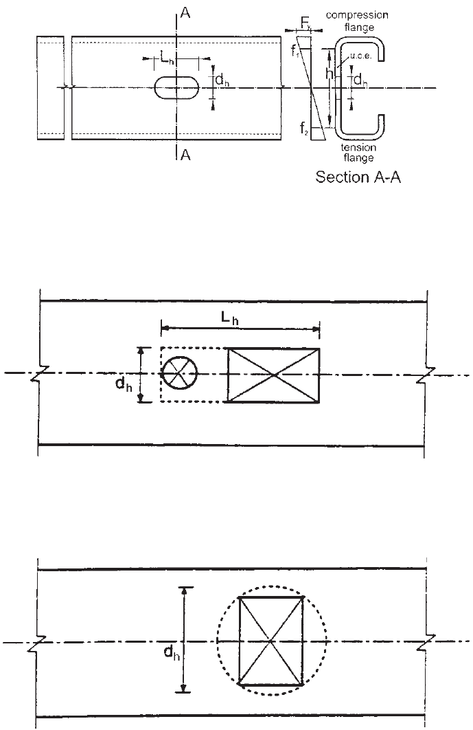
The design provisions apply to any hole pattern that
fits within equivalent virtual holes, as shown in Figs. 3.64
and 3.65. Figure 3.64 shows the dimensions L
h
and d
h
94 3 STRENGTH OF THIN ELEMENTS AND DESIGN CRITERIA
Figure 3.63 C-section webs with holes under stress gradient.
Figure 3.64 Virtual hole method for multiple openings.
1.333
Figure 3.65 Virtual hole method for opening exceeding limit.
1.333