Zuo-Guang. Ye Advanced Dielectric Piezoelectric and Ferroelectric Materials: Synthesis, Characterisation and Applications
Подождите немного. Документ загружается.


Handbook of dielectric, piezoelectric and ferroelectric materials480
superposition of the following two steps: first, the sample is completely
clamped and the field E
0
is applied (pure electrical energy (1/2) ε
x
ε
0
E
0
2
is
input); second, keeping the field at E
0
, the mechanical constraint is released
(additional mechanical energy (1/2) (d
2
/s
E
)
E
0
2
is necessary). The total energy
should correspond to the total input electrical energy (1/2) ε
X
ε
0
E
0
2
. Similar
energy calculation can be obtained from the bottom of Fig. 16.2, leading to
the following equations:
ε
x
/ε
X
= (1 – k
2
) 16.21
s
D
/s
E
= (1 – k
2
) 16.22
κ
X
/κ
x
= (1 – k
2
) 16.23
c
E
/c
D
= (1 – k
2
) 16.24
where
k
d
s
h
c
Ex Dx
2
2
0
2
0
= =
εε κκ
16.25
This k is called the electromechanical coupling factor, which is defined as a
real number in this chapter.
In order to obtain the relationships between the intensive and extensive
losses, the following three equations are essential:
εε κκ
κκ
00
2
0
–1
=
1 –
Xx
Dx
h
c
16.26
sc
h
c
ED
Dx
=
1 –
2
0
–1
κκ
16.27
d
h
c
h
h
c
Dx Dx
=
1 –
2
0
2
0
–1
κκ κκ
16.28
Replacing the parameters in Eqs. (16.26) and (16.27) by the complex parameters
in Eqs. (16.3) – (16.5), (16.16) – (16.18), we obtain the relationships between
the intensive and extensive losses:
tan δ′ =
1
1 –
2
k
[tan δ + k
2
(tan φ – 2 tan θ)] 16.29
tan φ′ =
1
1 –
2
k
[tan φ + k
2
(tan δ – 2 tan θ)] 16.30
tan θ′ =
1
1 –
2
k
[tan δ + tan φ + (1 + k
2
) tan θ] 16.31
where k is the electromechanical coupling factor defined by Eq. (16.25), and
WPNL2204

Loss mechanisms and high-power piezoelectric components 481
here as a real number. It is important that the intensive dielectric and elastic
losses are mutually correlated with the extensive dielectric, elastic and
piezoelectric losses through the electromechanical coupling k
2
, and that the
denominator (1 – k
2
) comes basically from the ratios, ε
x
/ε
X
= (1 – k
2
) and s
D
/
s
E
= (1 – k
2
), and this real part reflects to the dissipation factor when the
imaginary part is divided by the real part.
Expanding the discussion above, we introduce various loss formulas, as
summarized in Fig. 16.3, where the relationship between the vibration mode
and the corresponding elastic loss formula is provided. Refer to Bhattacharya
and Uchino [5] for further explanation.
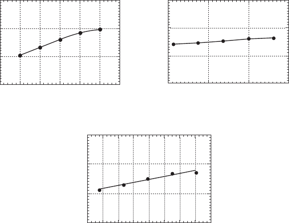
16.2.2 Experimental example
We determine ‘intensive’ dissipation factors first from (a) D vs. E (stress-
free), (b) x vs. X (short-circuit), (c) x vs. E (stress-free) and (d) D vs. X
(short-circuit) curves for a soft PZT-based multilayer actuator [6]. Then, we
calculate the ‘extensive’ losses as shown in Fig. 16.4. Note that the piezoelectric
losses tan
θ
′ and tan
θ
are not so small as previously believed, but comparable
to the dielectric and elastic losses, and increase gradually with the field or
stress. Also it is noteworthy that the extensive dielectric loss tan
δ
increases
significantly with an increase of the intensive parameter, i.e. the applied
electric field, while the extensive elastic loss tan
φ
is rather insensitive to the
intensive parameter, i.e. the applied compressive stress. With similar
measurements to Fig. 16.1(a) and 1(b), but under constrained conditions, i.e.
D vs. E under a completely clamped state, and x vs. X under an open-circuit
Elastic Gibbs
Free energy
Gibbs
Free energy
Helmholtz
Free energy
Gibbs
Free energy
Helmholtz
Free energy
k
31
mode
k
15
mode
Phenomenology
k
33
mode
k
t
mode
k
p
mode
tan =
G
11
11
φ
s
s
E
E
′′
′
tan =
G1
33
33
φ
s
s
D
D
′′
′
tan =
H
44
44
φ
c
c
D
D
′′
′
tan =
H
33
33
φ
c
c
D
D
′′
′
16.3
Relationship between the vibration mode and the corresponding
elastic loss.
WPNL2204
Handbook of dielectric, piezoelectric and ferroelectric materials482
state, respectively, we can expect smaller hystereses, that is, extensive losses,
tan
δ
and tan
φ
. These measurements seem to be alternative methods to determine
the three losses separately; however, they are rather difficult in practice.
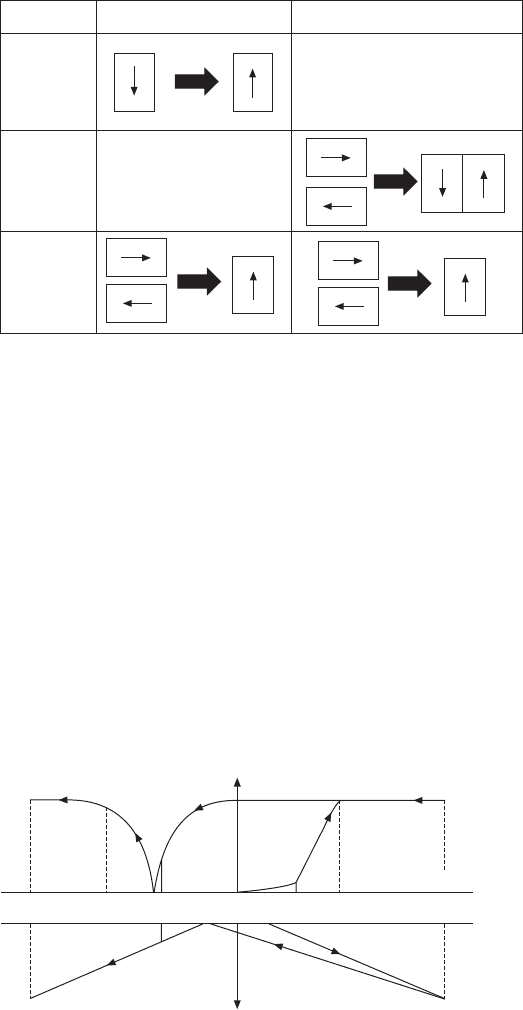
16.2.3 Physical meaning of extensive losses
To make the situation simplest, we consider here only the domain wall
motion-related losses. Taking into account the fact that the polarization change
is primarily attributed to 180° domain wall motion, while the strain is attributed
to 90° (or non-180°) domain wall motion, we suppose that the extensive
dielectric and mechanical losses are originated from 180° and 90° domain
wall motions, respectively, as illustrated in Fig. 16.5. The dielectric loss
comes from the hysteresis during the 180° polarization reversal under E,
while the elastic loss comes from the hysteresis during the 90° polarization
reorientation under X. In this model, the intensive (observable) piezoelectric
loss is explained by the 90° polarization reorientation under E, which can be
realized by superimposing the 90
o
polarization reorientation under X and the
180° polarization reversal under E. This is the primary reason why Eq.
(16.11) includes a combination term as (2 tanθ′ – tanφ′).
tan δ
0.15
0.1
0.05
0
tan φ
0.15
0.1
0.05
0
0.4 0.5 0.6 0.7 0.8 0.9 1
Electric field (kV/mm)
15 20 25 30
Compressive stress (MPa)
Electric field (kV/mm)
0.5 0.6 0.7 0.8 0.9
tan θ
0.15
0.1
0.05
0
14 16 18 20 22 24 26 28 30
Compressive stress (MPa)
16.4
Extensive loss factors, tanδ, tanφ and tanθ as a function of
electric field or compressive stress, measured for a PZT-based
actuator.
WPNL2204
Loss mechanisms and high-power piezoelectric components 483
If we adopt the Uchida–Ikeda polarization reversal/reorientation model
[7], we can explain the loss change with intensive parameter (externally
controllable parameter). By finding the polarization P and the field-induced
strain x as a function of the electric field E, it is possible to estimate the
volume in which a 180° reversal or a 90° rotation occurred. This is because
the 180° domain reversal does not contribute to the induced strain, only the
90° rotation does, whereas the 180° domain reversal contributes mainly to
the polarization. The volume change of the domains with external electric
field is shown schematically in Fig. 16.6. It can be seen that with the application
of an electric field the 180° reversal occurs rapidly whereas the 90° rotation
occurs slowly. It is notable that at G in the figure, there remains some
polarization while the induced strain is zero, at H the polarizations from the
Electric field Stress
Dielectric
tan δ
Mechanical
tan φ
Piezoelectric
tan θ
Strain
Polarization
Strain
16.5
Polarization reversal/reorientation model for explaining
dielectric, elastic and piezoelectric losses.
180° reversal
volume change
Electric field
90° reorientation
volume change
K J I H G(F,A) B C D E
16.6
Polarization reversal/reorientation model for explaining the loss
change with electric field.
WPNL2204
Handbook of dielectric, piezoelectric and ferroelectric materials484
180° and 90° reorientations cancel each other and become zero, but the
strain is not at its minimum. Owing to a sudden change in the 180° reversal
above a certain electric field, we can expect a sudden increase in the polarization
hysteresis and in the loss (this may reflect to the extensive dielectric loss
measurement in Fig. 16.4 top left); while the slope of 90° reorientation is
almost constant, we can expect a constant loss or a mechanical quality factor
Q
m
with changing the external parameter, E or X (extensive elastic loss in
Fig. 16.4 top right). This situation will be discussed again in the following
section.
16.3 Losses at a piezoelectric resonance
So far, we have considered the losses for a quasi-static or off-resonance
state. Problems in ultrasonic motors which are driven at the resonance frequency
include significant distortion of the admittance frequency spectrum due to
the nonlinear behavior of elastic compliance at a high vibration amplitude,
and the heat generation which causes a serious degradation of the motor
characteristics through the depoling of the piezoceramic. Therefore, the
ultrasonic motor requires a very hard type piezoelectric with a high mechanical
quality factor Q
m
, leading to the suppression of heat generation. It is also
notable that the actual mechanical vibration amplitude at the resonance
frequency is directly proportional to this Q
m
value.
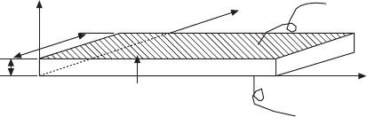
16.3.1 Vibration at a piezoelectric resonance
Let us review the longitudinal mechanical vibration of a piezoceramic plate
through the transverse piezoelectric effect (d
31
) as shown in Fig. 16.7 [8].
Assuming that the polarization is in the z-direction and the x–y planes are the
planes of the electrodes, the extensional vibration in the x direction is
represented by the following dynamic equation:
(∂
2
u/∂ t
2
) = F = (∂X
11
/∂x) + (∂X
12
/∂y) + (∂X
13
/∂z) 16.32
where u is the displacement of the small volume element in the ceramic plate
in the x-direction. When the plate is very long and thin, X
2
and X
3
may be set
z
w
b
0
P
z
L
x
y
16.7
Longitudinal vibration through the transverse piezoelectric effect
(d
31
) in a rectangular plate.
WPNL2204
Loss mechanisms and high-power piezoelectric components 485
equal to zero through the plate, and the following solutions can be obtained:
(strain)
∂
∂
u
x
xdE
Lxv xv
Lv
= =
[sin ( – )/ + sin( / )]
sin( )
131
Z
ωω
ω /
16.33
(total displacement)
∆ωωLxxELvLLv
L
= d = d (2 / ) tan( /2 )
0
131
Z
∫
16.34
Here, v is the sound velocity in the piezoceramic which is given by
vs
E
= 1/
11
ρ
16.35
The admittance for the mechanically free sample is calculated to be:
Y = (1/Z) = (i/V) = (i/E
z
t)
= ( / )
1 + ( / )(tan( /2 )
/2
0
3
31
2
0
311
jwLt
dsLv
Lv
LC
LC E
ωεε
εε ω
ω
16.36
where w is the width, L the length, t the thickness of the sample, and V the
applied voltage.
ε
3
LC
is the permittivity in a longitudinally clamped sample,
which is given by
εε εε εε
0
3
0
331
2
11
0
331
2
= – ( / ) = (1 – )
LC x E x
ds k
16.37
Now, we will introduce the complex parameters into the admittance curve
around the resonance frequency, in a similar way to the previous section:
εε
33
=
x
x
∗
(1 – jtan δ′),
ss j dd
E
E
11 11
31
*
= (1 – tan ), and =
∗
′
φ
(1– j tan θ′) into
Eq. (16.36):
Y = Y
d
+ Y
m
= (1 – tan ) + [(1– (2tan –tan )
(tan( /2 )
(/2*)
dd
31
2
jC j jCK j
Lv
Lv
ωδω θφ
ω
ω
′′
×
∗
16.38
where
CwL/t
x
00
3
= ( ) εε
16.39
CkC
d
31
2
0
= (1 – )
16.40
Note that the loss for the first term (damped conductance) is represented
by the ‘extensive’ dielectric loss tan δ, not by the intensive loss tan δ′. We
further calculate 1/[tan(ωL/2v
*
)] with an expansion-series approximation
around (ωL/2v) = π/2, taking into account that the resonance state is defined
in this case for the maximum admittance point.
Using new frequency parameters,
WPNL2204

Handbook of dielectric, piezoelectric and ferroelectric materials486
Ω = ωL/2 v, ∆Ω = Ω − π/2 (<<1) 16.41
and
Kk k
31
2
31
2
31
2
= /(1 – )
, the motional admittance Y
m
is approximated around
the first resonance frequency by
Yj CK
j
j
m
2
0
d
31
2
= (8/ )
(1 + ((3/2)tan – 2tan )
– (4/ ) tan
π
π
ω
φθ
∆φ
′′
Ω+
′
16.42
The maximum Y
m
is obtained at ∆Ω = 0:
YCK CKQ
m
max 2
0
d
31
2–12
0
d
31
2
m
= (8/ ) (tan ) = (8/ )ππωφ ω
′
16.43
where Q
m
= (tan φ′)
–1
. Similarly, the maximum displacement u
max
is obtained
at ∆Ω = 0:
u
max
= (8/π
2
) d
31
E
z
L Q
m
16.44
The maximum displacement at the resonance frequency is (8/π
2
)Q
m
times
larger than that at a non-resonance frequency, d
31
E
z
L.
In a brief summary, when we observe the admittance or displacement
spectrum as a function of drive frequency, and obtain the mechanical quality
factor Q
m
estimated from Q
m
= ω
0
/2∆ω, where 2∆ω is a full width of the
3 dB down (i.e. 1/√2) of the maximum value at ω = ω
0
, we can obtain the
intensive mechanical loss tan φ′.
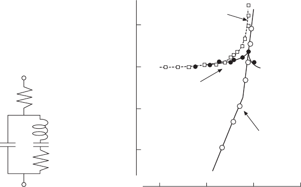
16.3.2 Equivalent circuit under high-power drive
The equivalent circuit for the piezoelectric actuator is represented by a
combination of L, C and R. Figure 16.8(a) shows an equivalent circuit for the
resonance state, which has very low impedance. Taking into account Eq.
(16.42), we can understand that C
d
and R
d
correspond to the electrostatic
capacitance (for a longitudinally clamped sample in the previous case, not a
free sample) and the clamped (or ‘extensive’) dielectric loss tan δ, respectively,
and the components L
A
and C
A
in a series resonance circuit are related to the
piezoelectric motion. For example, in the case of the longitudinal vibration
of the above rectangular plate through d
31
, these components are represented
approximately by
LLbwsd
A
11
E2
31
2
= ( /8)( / )[( ) / ]ρ
16.45
CLwbds
A
2
31
2
11
E
= (8/)( /)( /)π
16.46
The total resistance R
A
(= R
d
+ R
m
) should correspond to the loss tan φ′,
which is composed of the extensive mechanical loss tan φ and dielectric/
piezoelectric coupled loss (tan δ – 2tan θ) (see Eq. (16.30)). Thus, intuitively
speaking, R
d
and R
m
correspond to the extensive dielectric and mechanical
losses, respectively. Note that we have introduced an additional resistance R
d
WPNL2204
Loss mechanisms and high-power piezoelectric components 487
to explain a large contribution of the dielectric loss when a vibration velocity
is relatively large. There are, of course, different ways to introduce R
d
in an
equivalent circuit [9].
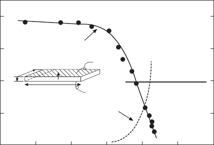
16.3.3 Losses as a function of vibration velocity
Let us consider here the degradation mechanism of the mechanical quality
factor Q
m
with increasing electric field and vibration velocity. Figure 16.9
shows the change in mechanical Q
m
with vibration velocity. Q
m
is almost
constant for a small electric field/vibration velocity, but above a certain
vibration level Q
m
degrades drastically, where temperature rise starts to be
observed [10].
Figure 16.8(b) depicts an important notion on heat generation from the
piezoelectric material, where the damped and motional resistances, R
d
and
R
m
, in the equivalent electrical circuit of a PZT sample (Fig. 16.8a) are
separately plotted as a function of vibration velocity. Note that R
m
, mainly
related to the extensive mechanical loss (90° domain wall motion), is insensitive
to the vibration velocity, while R
d
, related to the extensive dielectric loss
(180
o
domain wall motion), increases significantly around a certain critical
R
d
C
d
L
A
C
A
R
m
(a)
R
d
,
R
m
, and
R
A
(Ω)
100
30
10
3.0
0.03 0.1 0.3 1.0
Vibration velocity
v
0
(m/s)
(b)
R
A
(directly measured)
=
R
d
+
R
m
R
m
= ω
A
L
A
/
Q
B
R
d
= tan δ/ω
A
C
d
16.8
(a) Equivalent circuit of a piezoelectric device for the resonance
under high power drive. (b) Vibration velocity dependence of the
resistances
R
d
and
R
m
in the equivalent electric circuit for a
longitudinally vibrating PZT ceramic transducer through the
transverse piezoelectric effect
d
31
. Note a dramatic change in
R
d
above a certain threshold vibration velocity.
WPNL2204
Handbook of dielectric, piezoelectric and ferroelectric materials488
vibration velocity. Thus, the resonance loss at a small vibration velocity is
mainly determined by the extensive mechanical loss which provides a high
mechanical quality factor Q
m
, and with increasing vibration velocity, the
extensive dielectric loss contribution significantly increases. This is consistent
with the discussion on Fig. 16.6. After R
d
exceeds R
m
, we started to observe
heat generation.
16.4 Heat generation in piezoelectrics
Heat generation in various types of PZT-based actuators has been studied
under a large electric field applied (1 kV/mm or higher) at an off-resonance
frequency and under a relatively small electric field applied (100 V/mm) at
a resonance frequency.
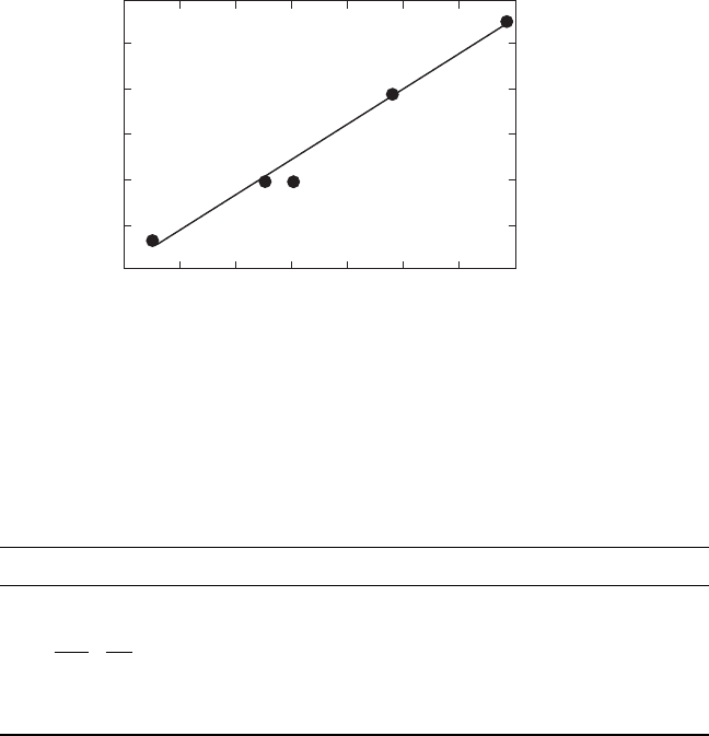
Zheng et al. reported the heat generation at an off-resonance frequency
from various sizes of multilayer-type piezoelectric ceramic actuators [6].
The temperature change with time in the actuators was monitored when
driven at 3 kV/mm and 300 Hz, and Fig. 16.10 plots the saturated temperature
as a function of V
e
/A, where V
e
is the effective volume (electrode overlapped
part) and A is the surface area. This linear relation is reasonable because the
volume V
e
generates the heat and this heat is dissipated through the area A.
Thus, if we need to suppress the temperature rise, a small V
e
/A design is
preferred. From these experimental results, we calculated the total loss u of
the piezoelectric, which is summarized in Table 16.I. The experimental data
of P–E hysteresis losses under a stress-free condition is also listed for
Q
A
2
43
Test sample
A-type
Temperature
rise
Mechanical
Q
m
2000
1500
1000
500
0
0.01 0.02 0.05 0.1 0.2 0.5 1
Vibration velocity
v
0
(m/s)
40
30
20
10
0
Temperature rise ∆
T
(°C)
16.9
Vibration velocity dependence of the quality factor
QA
and
temperature rise for A (resonance) type resonance of a longitudinally
vibrating PZT ceramic transducer through the transverse piezoelectric
effect
d
31
. The maximum vibration velocity is defined at the velocity
where a 20 °C temperature rise from room temperature occurs.
7
WPNL2204
Loss mechanisms and high-power piezoelectric components 489
comparison. It is very important that the P–E hysteresis intensive loss agrees
well with the total loss contributing to the heat generation under an off-
resonance drive.
Tashiro et al. observed the heat generation in a rectangular piezoelectric
plate during a resonating drive [11]. Even though the maximum electric field
is not very large, heat is generated due to the large induced strain/stress at the
resonance. Figure 16.11 depicts an infrared image taken for a resonating
rectangular PZT plate in our laboratory. The maximum heat generation was
observed at the nodal point of the resonance vibration, where the maximum
strain/stress is generated. This observation supports that the heat generation
in a resonating sample is attributed to the intensive elastic loss tan φ′. This
is not contradictory to the result in the previous paragraph, where a high
voltage was applied at an off-resonance frequency. We concluded there that
the heat is originated from the intensive dielectric loss tan δ′. In consideration
∆
T
(°C)
120
100
80
60
40
20
0
0 0.1 0.2 0.3 0.4 0.5 0.6 0.7
V
e
/
A
(mm)
16.10
Temperature rise at off-resonance versus
V
e
/A (3 kV/mm,
300 Hz) in various size soft PZT multilayer actuators, where
V
e
is the
effective volume generating the heat and
A
is the surface area
dissipating the heat.
Table 16.1
Loss and overall heat transfer coefficient for PZT multilayer samples
(
E
= 3 kV/mm,
f
= 300 Hz). The effective heat transfer coefficient here is the sum of
the rates of heat flow by radiation and by convection, neglecting the conduction
effect
Actuator 4.5 × 3.5 × 2mm
3
7 x 7 × 2 mm
3
17 × 3.5 × 1 mm
3
Total loss (×10
3
J/m
3
) 19.2 19.9 19.7
u
c
fv
T
t
t
=
v
d
d
e
0
ρ
≥
P
–
E
hysteresis loss (×10
3
J/m
3
) 18.5 17.8 17.4
k
(
T
) (W/m
2
K) 38.4 39.2 34.1
WPNL2204