Zuo-Guang. Ye Advanced Dielectric Piezoelectric and Ferroelectric Materials: Synthesis, Characterisation and Applications
Подождите немного. Документ загружается.

Handbook of dielectric, piezoelectric and ferroelectric materials490
16.11
An infrared image of a ‘hard’ PZT rectangular plate driven at
the second resonance mode. Note the three hot points which
correspond to the nodal points for this vibration mode.
that both the ‘intensive’ dielectric and mechanical losses are composed of
the ‘extensive’ dielectric and mechanical losses, and that the extensive dielectric
loss tan δ changes significantly with the external electric field and stress, the
major contribution to the heat generation seems to come from the ‘extensive’
dielectric loss (i.e. 180° domain wall motion). Since this is just our model,
there can be different domain reorientation models, and further investigations
are waited for the microscopic observation of this phenomenon.
16.5 Loss anisotropy
Typically the specification sheet provided by the manufacturer gives only
one mechanical quality factor (Q
m
) and one dielectric loss tangent, which are
applicable only for the k
31
length extensional mode (i.e. imaginary parts of
s
11
E
and
ε
33
X
, respectively). Losses can be, in general, introduced in the
complex material constants, where the real part indicates the usual material
constant and the imaginary part indicates the loss. As introduced in the
previous section in Fig. 6.3, in order to determine the loss tangent as a
tensor, the phenomenology for lateral (k
31
), longitudinal (k
33
), thickness (k
t
)
and shear (k
15
) modes has been repeated with complex material constants.
The theoretical thermodynamic analysis has been performed by considering
the intensive variables, stress and electric field (relating to generalized forces),
WPNL2204
Loss mechanisms and high-power piezoelectric components 491
and extensive variables, strain and electric displacement (relating to generalized
displacement), and four distinct phase angles, identified by their respective
free energies (denoted as Helmholtz loss tangent, Gibbs loss tangent, electric
Gibbs loss tangent and elastic Gibbs loss tangent). The data for the Gibbs
tangents for typical ‘soft’ and ‘hard’ piezoceramics (APC-850 and 841,
American Piezo Ceramics, PA) is presented in Table 16.2. The detailed
measuring technique and processes are reported in Ref. [5]. Note that the
Q
m
(= 222) for the k
33
mode (imaginary part of
s
33
E
) is only 1/5 of that
(= 1087) for the k
31
mode (imaginary part of
s
11
E
).
This significant anisotropy in Q
m
reflects largely in designing the transducers
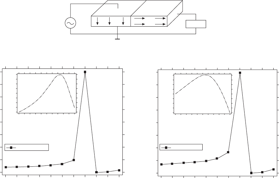
and transformers. Figure 16.12 exhibits an important example simulated for
a Rosen-type piezoelectric transformer, which includes both k
33
and k
31
mode
in one device. We adopted ATILA Finite Element Method software (ISEN,
distributed by Micromecharonics Inc., PA) for simulating a Rosen-type
piezoelectric transformer with 40 mm in length (see Fig. 16.12a). Figures
12(b) and 16.12(c) show admittance spectra simulated for an isotropic loss
condition (Q
m
= 1087) and for an anisotropic loss condition (Q
m
= 1087 and
222). As shown in the inserted magnified spectra, a half of the admittance
value at the peak is significant, as well as a slight resonance peak shift to a
lower frequency. Without knowing the peak admittance, it is difficult to
design a drive circuit for this transformer.
16.6 High-power piezoelectric ceramics
16.6.1 Very hard PZT-based ceramics
‘High power’ in this chapter stands for high-power density in mechanical
output energy converted from the maximum input electrical energy under
the drive condition with 20 °C temperature rise. For an off-resonance drive
condition, the figure of merit of piezo-actuators is give by the piezoelectric
d constant (∆L = dEL). Heat generation can be evaluated by the intensive
dielectric loss tan δ′ (i.e. P–E hysteresis).
In contrast, for a resonance drive condition, the figure of merit is the
vibration velocity v
0
, which is roughly proportional to Q
m
dEL. Heat generation
is originated from the intensive elastic loss tan φ′ (inverse value of Q
m
). The
mechanical power density can be evaluated by the square of the maximum
vibration velocity
()
0
2
v
, which is a sort of material constant. Remember that
there exists the maximum mechanical energy density, above which level the
piezoelectric material becomes a ceramic heater. High-vibration velocity
materials are suitable for actuator applications such as ultrasonic motors.
Further, when we consider transformers and transducers, where both
transmitting and receiving functions are required, the figure of merit will be
the product of v
0
k (k: electromechanical coupling factor).
WPNL2204

Handbook of dielectric, piezoelectric and ferroelectric materials492
Table 16.2
Gibbs loss tangents for typical ‘soft’ and ‘hard’ piezoceramics (APC-850 and 841, American Piezo Ceramics, PA)
Complex material APC850 (‘Soft Ceramic’) APC841 (‘hard ceramic’)
constant
Real part Imaginary part Loss tangent Real part Imaginary part Loss tangent
Elastic compliance (10
–12
m
2
/N)
S
11
E*
16.9 –0.205 –0.012 2 11.4 –0.010 5 –0.000 92
S
12
E*
–6.4 0.0779 –0.012 1 –3.42 0.003 83 –0.001 12
S
13
E*
–5.6 0.067 –0.011 98 –5.65 –0.032 0.005 66
S
33
E*
17.4 –0.347 –0.02 15.35 –0.069 2 –0.004 51
S
44
E*
52.6 –3.82 –0.072 56 20.8 –0.24 –0.011 5
S
66
E*
46.7 –1.968 –0.042 29.64 –0.028 –0.000 945
Dielectric constant (10
–9
F/m)
ε
11
T*
10.01 0.346 –0.0346 12 –0.048 –0.004
ε
33
T*
15.8 –0.34 –0.022 18 –0.162 –0.009
WPNL2204
Loss mechanisms and high-power piezoelectric components 493
Admittance magnitude
Admittance magnitude
U
in
P
Load
(a)
Admittance magnitude (S)
40000 40800 41600 42400 43200 44000 44800 45600 46400 47200 48000
Frequency (Hz)
(b)
0.004573
0.004012
0.003451
0.00289
0.002329
0.001768
0.001207
0.000646
8.5e-05
Admittance magnitude (S)
0.003868
0.00365
0.003432
0.003214
0.00299
0.002778
0.00256
0.002342
0.002124
64600
64620
64640
64660
64680
64700
64720
64740
64760
64780
64800
Frequency (Hz)
Admittance magnitude (S)
40000 40800 41600 42400 43200 44000 44800 45600 46400 47200 48000
Frequency (Hz)
(c)
0.002624
0.002308
0.001992
0.001676
0.00136
0.001044
0.000728
0.000412
9.6e-05
Admittance magnitude (S)
0.002248
0.00217
0.002092
0.002014
0.001936
0.001858
0.00178
0.001702
0.001624
64600
64620
64640
64660
64680
64700
64720
64740
64760
64780
64800
Frequency (Hz)
0.0039
64.75 kHz
0.0022
64.71 kHz
16.12
(a) Schematic structure of a Rosen-type piezoelectric transformer (40 mm in length); (b) admittance spectrum
simulated for an isotropic loss condition (
Q
m
= 1087), and admittance spectrum for an anisotropic loss condition (
Q
m
=
1087 and 222).
WPNL2204
Handbook of dielectric, piezoelectric and ferroelectric materials494
Let us discuss high-vibration velocity materials first. Figure 16.13 shows
the mechanical Q
m
versus basic composition x at two effective vibration
velocities v
0
= 0.05 m/s and 0.5 m/s for Pb(Zr
x
Ti
1–x
)O
3
doped with 2.1 at.%
of Fe [12]. The decrease in mechanical Q
m
with an increase of vibration
level is minimum around the rhombohedral–tetragonal morphotropic phase
boundary (52/48). In other words, the smallest Q
m
material under a small
vibration level becomes the highest Q
m
material under a large vibration
level, and the data obtained by a conventional impedance analyzer with a
small voltage/power do not provide any information relevant to high-power
characteristics. Thus, we have developed various measuring techniques of
high-power piezoelectricity, including ‘constant current’ and ‘pulse drive’
methods [13].
Conventional piezoceramics have a limitation in the maximum vibration
velocity (v
max
), since the additional input electrical energy is converted into
heat, rather than into mechanical energy. The typical rms value of v
max
for
commercially available materials, defined by the temperature rise of 20 °C
from room temperature, is around 0.3 m/s for rectangular samples operating
in the k
31
mode (like a Rosen-type transformer) [10]. Pb(Mn,Sb)O
3
(PMS)–
lead zirconate titunate (PZT) ceramics with a v
max
of 0.62 m/s are currently
used for NEC transformers [12]. By doping the PMS–PZT or Pb(Mn,Nb)O
3
–
PZT with rare-earth ions such as Yb, Eu and Ce, we recently developed
high-power piezoelectrics, which can operate with v
max
up to 1.0 m/s [14,
15]. Compared with commercially available piezoelectrics, 10 times higher-
Mechanical quality factor
Q
m
2000
1000
Mechanical Quality factor
Q
m
Pb(Zr
x
Ti
1–
x
)O
3
+ 2.1 at% Fe
Vibration velocity
v
0
= 0.05 m/s
v
0
= 0.5 m/s
600
400
200
0.48 0.50 0.52 0.54 0.56 0.58
Mole fraction of Zr (
x
)
16.13
Mechanical
Q
m
versus basic composition
x
at two effective
vibration velocities
v
0
= 0.05 m/s and 0.5 m/s for Pb(Zr
x
Ti1–
x
)O
3
doped
with 2.1 at.% of Fe.
WPNL2204
Loss mechanisms and high-power piezoelectric components 495
input electrical energy and output mechanical energy can be expected from
these new materials without generating a significant temperature rise, which
corresponds to 100 W/cm
2
. Figure 16.14 shows the dependence of the maximum
vibration velocity v
0
(20 °C temperature rise) on the atomic % of rare-earth
ion, Yb, Eu or Ce in the Pb(Mn,Sb)O
3
(PMS)–PZT-based ceramics.
Enhancement in the v
0
value is significant by adding a small amount of the
rare-earth ion [15].
16.6.2 Origin of high-power piezoelectrics
‘Hard’ PZT is usually used for high-power piezoelectric applications, because
of its high coercive field, in other words, the stability of the domain walls.
Acceptor ions, such as Fe
3+
, introduce oxygen deficiencies in the PZT crystal
(in the case of donor ions, such as Nb
5+
, Pb deficiency is introduced). Thus,
in the conventional model, the acceptor doping causes domain pinning through
the easy reorientation of deficiency-related dipoles, leading to ‘hard’
characteristics (domain wall pinning model [16]). In this section, we explore
the origin of our high-power piezoelectric ceramics.
High mechanical Q
m
is essential in order to obtain a high-power material
with a large maximum vibration velocity. Figure 16.15 exhibits suggestive
results in the mechanical Q
m
increase with time lapse (minute) after the
electric poling measured for various commercial soft and hard PZTs, PSM–
PZT, and PSM–PZT doped with Yb. It is notable that the Q
m
values for
commercial hard PZT and our high power piezoelectrics were almost the
same, slightly higher than soft PZTs, and around 200–300 immediately
after the poling. After a couple of hours, the Q
m
values increased more than
Yb
Eu
Ce
Maximum vibration velocity (m/s)
1.1
1.0
0.9
0.8
0.7
0.6
0.5
0 0.01 0.02 0.03 0.04 0.05 0.06 0.07
Doping concentration (atom ratio)
16.14
Dependence of the maximum vibration velocity
v
0
(20 °C
temperature rise) on the atomic % of rare-earth ion, Yb, Eu or Ce in
the Pb(Mn, Sb)O
3
(PMS)–PZT based ceramics.
WPNL2204
Handbook of dielectric, piezoelectric and ferroelectric materials496
1000 for the ‘hard’ materials, while no change was observed in the ‘soft’
material. The increasing slope is the maximum for the Yb-doped PSM-PZT.
We also found a contradiction that this gradual increase (in a couple of
hours) in the Q
m
cannot be explained by the above-mentioned ‘domain wall
pinning’ model, but more likely by some ionic diffusion model.
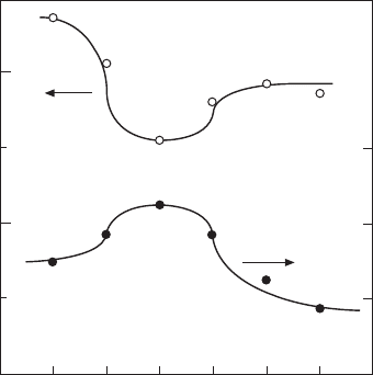
Figure 16.16 shows the polarization vs. electric field hysteresis curves
measured for the Yb-doped Pb(Mn,Sb)O
3
–PZT sample immediately after
PZT–PSM–Yb
PZT–PSM
Hard PZT
Soft PZT
Q
m
2000
1800
1600
1400
1200
1000
800
600
400
200
0
10 100 1000
Time (min)
16.15
Change in the mechanical
Q
m
with time lapse (minute) just
after the electric poling measured for various commercial soft and
hard PZTs, PSM–PZT, and PSM–PZT doped with Yb.
PZT–PSM–Yb fresh
PZT–PSM–Yb 48 h
PZT–PSM–Yb Aged
Polarization (C/m
2
)
0.3
0.2
0.1
0.0
–0.1
–0.2
–0.3
–40 –30 –20 –10 0 10 20 30 40
Electric field (kV/cm)
16.16
Polarization vs. electric field hysteresis curves measured for the
Yb-doped Pb(Mn,Sb)O
3
–PZT sample just after poling (fresh), 48 hours
after, and a week after (aged).
WPNL2204
Loss mechanisms and high-power piezoelectric components 497
poling (fresh), 48 hours after, and a week after (aged). Remarkable aging
effects could be observed: (a) in the decrease in the magnitude of the remnant
polarization and (b) in the positive internal bias electric field growth (i.e. the
hysteresis curve shift leftwards in terms of the external electric field axis).
The phenomenon (a) can be explained by the local domain wall pinning
effect, but the large internal bias (more than 1 kV/mm) growth (b) seems to
be the origin of the high-power characteristics. Suppose that the vertical axis
in Fig. 16.16 shifts rightwards, the inverse electric field required for realizing
the 180° polarization reversal is increased, leading to the resistance
enhancement against generating the hysteresis or heat.
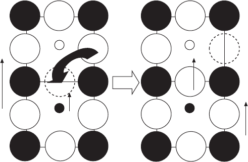
Finally, let us propose the origin of this internal bias field growth. Based
on the presence of the oxygen deficiencies and the relatively slow (a couple
of hours) growth rate, we assume here the oxygen deficiency diffusion model,
which is illustrated in Fig. 16.17. Under the electric poling process, the
defect dipole P
defect
(a pair of acceptor ion and oxygen deficiency) will be
arranged parallel to the external electric field. After removing the field,
oxygen diffusion occurs, which can be estimated in a scale of hour at room
temperature. Taking into account slightly different atomic distances between
the A and B ions in the perovskite crystal in a ferroelectric (asymmetric)
phase, the oxygen diffusion probability will be slightly higher for the downward,
as shown in the figure, leading to the increase in the defect dipole with time.
This may be the origin of the internal bias electric field.
16.6.3 Semi-hard PZT-based ceramics
Though the rare-earth doped PZT–Pb(Mn,Sb)O
3
system with the highest
vibration velocity satisfies actuator applications, due to relatively smaller
P
s
Diffusion
P
defect
Acceptor
P
de
E
B
16.17
Oxygen deficiency diffusion model for explaining the internal
bias electric field growth.
WPNL2204
Handbook of dielectric, piezoelectric and ferroelectric materials498
piezoelectric d constants, it cannot replace transducer or transformer materials,
where the direct piezoelectric effect is successively utilized to convert the
mechanical energy into final electrical energy. In this sort of electric–
mechanical–electric conversion application, since the figure of merit is v
0
k,
we modified the composition to improve the high Q
m
by sustaining the high
d and k, starting from originally soft Pb(Zn
1/3
Nb
2/3
)O
3
–Pb(Ni
1/3
Nb
2/3
)O
3
–
Pb(Zr
0.5
Ti
0.5
)O
3
. Sb, Li and Mn were substituted to the 0.8Pb(Zr
0.5
Ti
0.5
)O
3
–
0.16Pb(Zn
1/3
Nb
2/3
)O
3
–0.04Pb(Ni
1/3
Nb
2/3
)O
3
ceramics. The composition
0.8Pb(Zr
d
Ti
1–d
)O
3
–0.2Pb[(1–c){(1–b) (Zn
0.8
Ni
0.2
)
1/3
(Nb
1–a
Sb
a
)
2/3
–b(Li
1/4
(Nb
1–a
Sb
a
)
3/4
)}–c (Mn
1/3
(Nb
1–a
Sb
a
)
2/3
)]O
3
(a = 0.1, b = 0.3, c = 0.3 and
d = 0.5) showed the value of k
p
= 0.56, Q
m
= 1951 (planar mode), d
33
=
239 pC/N,
εε
3
T
0
/
= 739 and the maximum vibration velocity = 0.6 m/s at
31-mode. By adjusting the Zr/Ti ratio, compromised properties of k
p
= 0.57,
Q
m
= 1502 (planar mode), d
33
= 330 pC/N,
εε
3
T
0
/
= 1653 and the maximum
31-mode vibration velocity = 0.58 m/s were obtained when Zr/Ti = 0.48/
0.52 [17]. These compositions are suitable for piezoelectric transformers and
transducers.
16.7 High-power piezoelectric components
Though we have developed ‘high-power density’ piezoelectric ceramics, the
multilayer structure is a key to developing actual ‘high-power’ components
from the device-designing viewpoint. However, the present Ag–Pd electrode
structure includes two problems: (1) expensive Pd and (2) although Ag
migration during sintering and under electric field applied can be suppressed
by Pd, the electrode conductance is significantly decreased. The latter is the
major problem in designing multilayer transformers, because the electrode
loss appears to be large, leading to heat generation and low efficiency. In
order to solve the problems, pure Cu electrode will be a key. But, the multilayer
samples need to be sintered at a relatively low temperature (90 °C or lower)
in a reduced atmosphere, when utilizing Cu embedded electrodes. Thus, it is
necessary to develop low-temperature sintering of ‘hard’ type PZTs. Unlike
soft PZTs, most of the conventional dopants to decrease the sintering
temperature failed to be used, because these dopants also degrade the Q
m
value significantly.
We further modified our high-power piezoelectric ceramics, the Sb, Li
and Mn-substituted 0.8Pb(Zr
0.5
Ti
0.5
)O
3
–0.16Pb(Zn
1/3
Nb
2/3
)O
3
–0.04Pb(Ni
1/3
Nb
2/3
)O
3
, by adding CuO and Bi
2
O
3
in order to lower the sintering temperature
of the ceramics. Table 16.3 summarizes piezoelectric properties of semi-
hard piezoelectric ceramics based on Pb(Zn
1/3
Nb
2/3
)O
3
–Pb(Ni
1/3
Nb
2/3
)O
3
–
Pb(Zr
0.5
Ti
0.5
)O
3
, sinterable at 900 °C. Under a sintering condition of 900 °C
for 2 h, the properties were k
p
= 0.56 Q
m
(31-mode) = 1023, d
33
= 294 pC/N
ε
33
/ε
o
= 1282 and tanδ = 0.59%, when CuO and Bi
2
O
3
were added 0.5 wt%
each. The maximum vibration velocity of this composition was 0.41 m/s.
WPNL2204

Loss mechanisms and high-power piezoelectric components 499
Table 16.3
Piezoelectric properties of semi-hard piezoelectric ceramics based on Pb(Zn
1/3
Nb
2/3
)O
3
–Pb(Ni
1/3
Nb
2/3
)O
3
–Pb(Zr
0.5
Ti
0.5
)O
3
,
sinterable at 900 °C.
Composition Sintering
Q
m
Q
m
εε
3
T
0
/
d
33
k
p
k
31
T
c
(°C)
v
0
(m/s)
condition (planar) (31-mode)
HP-HT-6-2 1200/2 h 1951 1815 739 239 0.56 0.3 285.6 0.6
HP-HT-12-4 1200/2 h 1502 1404 1653 330 0.573 0.33 289.58 0.58
HP-LT-17-3 900/2 h 1282 * 1326 294 0.56 * * 0.41
*
On measuring.
HP-HT-6-2: Pb(Zr,Ti)-Pb(Zn,Ni)Nb with Sb, Li and Mn substitution.
HP-HT-12-4: Further modification on the HP-HT-6-2.
HP-LT-17-3: Low temperature sintering of the HP-HT-12-4 with CuO and Bi
2
O
3
.
WPNL2204