API RP 2T-2010 Planning, Designing, and Constructing Tension Leg Platforms
Подождите немного. Документ загружается.


PLANNING, DESIGNING, AND CONSTRUCTING TENSION LEG PLATFORMS 231
c is the fatigue ductility exponent (material constant).
C.6.2.2 Calculating
ε
re
The coefficients and exponents defined above are generated experimentally for the material in question, and
ε
re
may be obtained using the cyclic stress-strain relation for the material:
(C.2)
Here the cyclic strain-hardening coefficient (
K') and the cyclic strain-hardening exponent (n') are known
material constants determined experimentally. Calculating
σ
re
:
The equivalent fully reversible stress amplitude at the notch (
σ
re
) includes the effect of the mean stress at the
notch:
(C.3)
where
σ
a
is the elasto-plastic stress amplitude at the notch,
ar
1
2
σ
=σ
;
σ
r
is the elasto-plastic stress range at the notch [Figure C.1 c)];
σ
o
is the elasto-plastic mean stress at the notch [Figure C.1 c)].
C.6.2.3 Calculating
σ
r
and σ
o
Both
σ
r
and σ
o
may be obtained by transforming the elastic notch response obtained from FEA. This
transformation accounts for the local plasticity that takes place at the notch. The elastic notch response may
be given in terms of the stresses directly calculated at the notch; the nominal pipe stresses and a geometric
stress concentration factor (SCF), which relates the pipe stress (
S) to the notch stress (σ) (preferred); or a
combination of the two.
The elastic notch stresses may be transformed to elasto-plastic stresses by either of the following two
methods:
C.6.3 Strain Energy Method
The energy method simply equates the elastic strain energy at the notch to the elasto-plastic energy given by
the actual cyclic stress-strain behavior obtained experimentally for the material in question (see Figure C.3).
This transformation is general and accurate.
Knowing the elastic notch stress range and peak stress [Figure C.1(b)], the following equations apply:
ε
σσ
ε
re
re
E
re
K
n
Solve for
re
=+
⎛
⎝
⎜
⎞
⎠
⎟
→
'
'
1
(
)
σ
σ
σ
σ
σσσ
σ
re
a
o
f
oaa
Solve for
re
=
−
+
⎡
⎣
⎢
⎢
⎢
⎢
⎤
⎦
⎥
⎥
⎥
⎥
→
1
05
'
.
Copyright American Petroleum Institute
Provided by IHS under license with API
Licensee=Shell Global Solutions International B.V. Main/5924979112, User=Low, Ko
Not for Resale, 01/31/2011 00:10:44 MST
No reproduction or networking permitted without license from IHS
--``,`,```,,,``,`,``,,,,,,,,,,`-`-`,,`,,`,`,,`---

232 API RECOMMENDED PRACTICE 2T
(C.4)
(C.5)
The variables in the equations are as follows:
r
e
σ
is the elasto-stress range at the notch from FEA;
r
σ
is the elasto-plastic stress range (transformed) at the notch;
p
e
σ
is the elasto-peak stress at the notch from FEA;
p
σ
is the elasto-plastic peak stress (transformed) at the notch;
o
σ
is the elasto-plastic mean stress at the notch.
=
r
e
E
r
E
r
n
r
K
n
r
2
2
2
21
1
σσσσ
σ=+
+
⎛
⎝
⎜
⎞
⎠
⎟
→
'
'
'
Solve for
p
e
E
p
E
p
n
p
K
n
2
2
2
21
1
σσσσ
σ=+
+
⎛
⎝
⎜
⎜
⎞
⎠
⎟
⎟
→
'
'
'
Solve for
p
op
r
σσ
σ
=−
2
Copyright American Petroleum Institute
Provided by IHS under license with API
Licensee=Shell Global Solutions International B.V. Main/5924979112, User=Low, Ko
Not for Resale, 01/31/2011 00:10:44 MST
No reproduction or networking permitted without license from IHS
--``,`,```,,,``,`,``,,,,,,,,,,`-`-`,,`,,`,`,,`---
PLANNING, DESIGNING, AND CONSTRUCTING TENSION LEG PLATFORMS 233
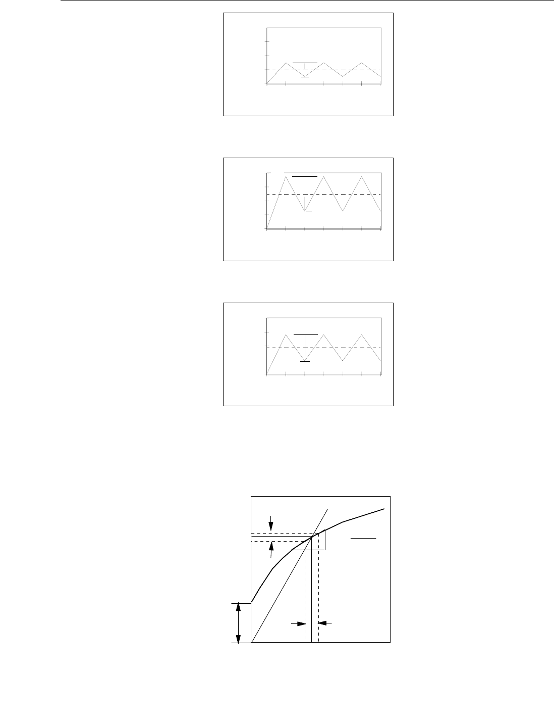
(a) Nominal Pipe Stress Variation
(b) Elastic Stresses at the Notch
(c) Transformed Notch Stresses
Figure C.1—Definition of Pipe and Notch Stresses
Figure C.2—Relation Between Notch and Pipe Stresses
Time Step
Applied Nominal
Pipe Load
0
2
4
6
8
0
1
2
3
4
5
6
r
S
o
S
Time Step
Elastic Notch
Response
0
2
4
6
8
0
1
2
3
4
5
6
SCF Effect
o
e
σ
r
e
σ
p
e
σ
Time Step
Elasto-Plastic
Notch Response
0
2
4
6
8
0
1
2
3
4
5
6
Plasticity Effect
o
σ
r
σ
p
σ
Notch
Stress
Pipe Stress
p
r
e
l
o
a
d
SCF
notch
pipe
=
Δ
Δ
σ
σ
S
o
Sr
Neuber's
r
σ
o
σ
Copyright American Petroleum Institute
Provided by IHS under license with API
Licensee=Shell Global Solutions International B.V. Main/5924979112, User=Low, Ko
Not for Resale, 01/31/2011 00:10:44 MST
No reproduction or networking permitted without license from IHS
--``,`,```,,,``,`,``,,,,,,,,,,`-`-`,,`,,`,`,,`---
234 API RECOMMENDED PRACTICE 2T
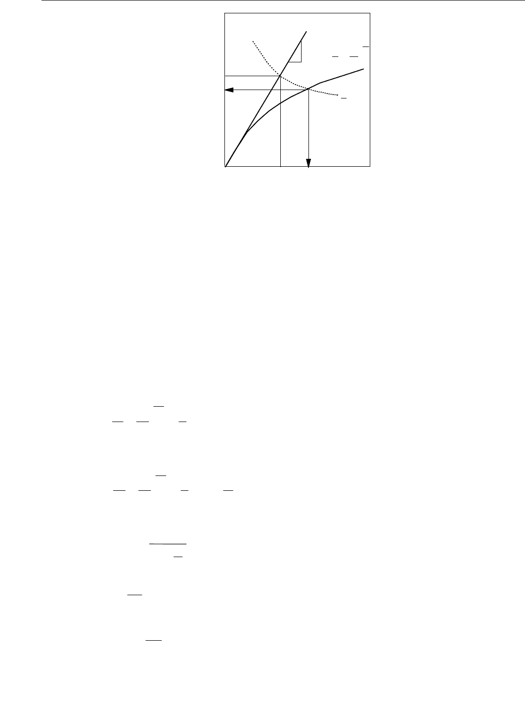
Figure C.3—Transformation of Elastic Stress via Strain Energy
C.6.4 Neuber’s Method
Neuber’s method represents an engineering approximation to the same transformation and is based on the
Neuber’s rule (the geometric mean of the strain and stress concentration factors remains constant with load)
and Peterson’s empirical fatigue strength reduction factor,
K
f
(Topper, 1969). Referring to Figure C.2, the
notch stress is linearly related to the pipe stress via an SCF and there is no initial pre-stress at the notch.
Two approaches can be followed to obtain the notch peak stress and stress range to calculate the notch
mean stress.
1) Knowing the nominal pipe stress range (
S
r
), the mean stress (S
o
) and the elastic SCF (from FEA), the
transformed elasto-plastic notch stress range (
σ
r
) and the peak notch stress (σ
p
) can be obtained
directly from the nominal pipe stresses (Figure C.5) according to the following two relations:
(C.6)
(C.7)
K
f
1+
SCF 1
1+
A
r
=
−
(C.8)
S
SCF
Δ
Δ
=
σ
(C.9)
(C.10)
ε
σσ
=+
⎛
⎝
⎜
⎞
⎠
⎟
E
K
n
'
'
1
E
1
ε
σ
elasto-
plastic
elastic
elastic
Areas under
curves equal
1
2
σε=A
A
elasto-
plastic
(
)
r
r
E
r
K
n
E
r
f
K
S
σ
σσ
σ+
⎛
⎝
⎜
⎜
⎞
⎠
⎟
⎟
⎡
⎣
⎢
⎢
⎢
⎢
⎢
⎤
⎦
⎥
⎥
⎥
⎥
⎥
=→
'
'
1
1
2
Solve for
r
p
p
E
p
K
n
E
f
KS
r
S
Solve for
σ
σσ
σ+
⎛
⎝
⎜
⎜
⎞
⎠
⎟
⎟
⎡
⎣
⎢
⎢
⎢
⎢
⎢
⎤
⎦
⎥
⎥
⎥
⎥
⎥
=+
⎛
⎝
⎜
⎞
⎠
⎟
→
'
'
1
1
2
0
2
2
p
A
u
=
⎛
⎝
⎜
⎞
⎠
⎟
0 821
300
18
.
.
σ
Copyright American Petroleum Institute
Provided by IHS under license with API
Licensee=Shell Global Solutions International B.V. Main/5924979112, User=Low, Ko
Not for Resale, 01/31/2011 00:10:44 MST
No reproduction or networking permitted without license from IHS
--``,`,```,,,``,`,``,,,,,,,,,,`-`-`,,`,,`,`,,`---
PLANNING, DESIGNING, AND CONSTRUCTING TENSION LEG PLATFORMS 235
The variables in the equations are as follows:
K
f
is the fatigue strength reduction factor or effective fatigue SCF;
r is the notch radius (in mm);
u
σ
is the ultimate stress of the material (in MPa);
o
σ
is the elasto-plastic mean stress at the notch.
is the
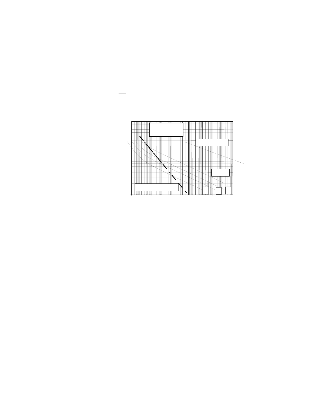
Figure C.4—Calculated S-N Curves using Initiation Life for Various SCFs and Constant Mean Stress
The accuracy of the transformation by the Neuber’s method depends on the relative contribution of
the connector preload to the notch stress and on the degree of nonlinearity between the notch stress
and the pipe stress. If linearity between the notch and pipe stresses exists and there is no preload,
the notch stresses can be calculated using the pipe stresses and an SCF, and the energy method
can alternatively be used.
If the local notch stress is not linearly related to the pipe stress and the connector is preloaded
(Figure C.4), then the SCF varies with the pipe stress and there is an initial stress at the notch that is
related not to the pipe stress, but to dimensional interferences in the connector. In this case, the
instantaneous SCF may be taken as the derivative of the notch stress with respect to the pipe stress
to relate the pipe stress range to the notch stress range. However, the pipe mean stress can no
longer be related to the notch stress via an SCF. To avoid this situation, the elastic mean stress
directly calculated at the notch via FEA is used.
2) Knowing the elastic mean notch stress (
σ
o
), the pipe stress range (S
r
) and the instantaneous SCF,
the transformed notch stress range (
σ
r
) and the notch peak stress (σ
p
) can also be obtained using
Neuber’s method by the following equations:
op
r
σσ
σ
=−
2
10
100
1000
1E+04 1E+06 1E+08 1E+10 1E+12 1E+14
N, Cycles
Pipe Stress, [MPa]
SCF=2
SCF=1, So=0
HY80 Material
So=690Mpa
3
4
6
Ground Girth Weld
Copyright American Petroleum Institute
Provided by IHS under license with API
Licensee=Shell Global Solutions International B.V. Main/5924979112, User=Low, Ko
Not for Resale, 01/31/2011 00:10:44 MST
No reproduction or networking permitted without license from IHS
--``,`,```,,,``,`,``,,,,,,,,,,`-`-`,,`,,`,`,,`---

236 API RECOMMENDED PRACTICE 2T
(C.11)
(C.12)
Here the elasto-plastic mean stress (σ
o
) at the notch is:
(C.13)
Using σ
r
and σ
o
in the equation for the equivalent fully reversible σ
re
, the corresponding strain ε
re
can
be calculated. With
σ
re
and ε
re
, it is possible to solve for N
f
in the first equation.
An example of S-N curves developed for an actual connector is presented in Figure C.5, compared to
a girth weld estimated as the D-curve. In this example, the connector in question develops preload
upon makeup, the notch stress is not linear with the pipe stress, and the notch mean stress is
690 MPa obtained from linear-elastic FEA (stresses greater than yield are allowed, since they are
transformed, as shown in Figure C.3).
SCFs and Constant Mean Stress
Properties:
n'= 0.147; K’ = 1184 MPa; = 1249 MPa
= 1.456;
b = -0.101; c = −0.693
C.7 Tendon Flex Element
Qualification and verification would also be required in the event that significant changes were made to the
materials and/or manufacturing method of an existing, well proven, design.
For flex elements consisting of the “traditional” elastomer/steel sandwich configuration, qualification of
manufacturability should include sacrificial testing of actual steel layers (commonly referred to as the flex
element shim) or of material clearly representative of the shims (i.e. formed with the same or equivalent
process, including forging reduction, heat treatment, etc. as appropriate) to verify achievement of acceptable
mechanical properties, as well as rigorous dimensional testing of the actual sets of shims. Furthermore,
testing should be performed of representative samples of the elastomeric layers recovered from full-scale
prototype fully molded flex elements. These tests should verify total curing of the elastomer and that expected
mechanical properties of the elastomer are achieved. In addition, tests should be performed of a prototype
flex element to verify that the proper relative position (within design tolerances) of the shims is achieved, and
that the elastomer pad thicknesses are within tolerance.
The flex element manufacturer should develop and implement a quality control process that verifies that
subsequently produced flex elements will be manufactured from materials of equivalent performance as
verified in the qualification tests, and that the dimensional features (pad thickness and shim relative position)
are verified following fabrication of all flex elements. The flex element manufacturer should also have means
to verify that the pad space (i.e. the volume between the shims) has been fully filled by elastomer, with
absence of voids sufficient to cause degradation of elastomeric fatigue performance. The flex element
(
)
r
r
E
r
K
n
E
r
f
K
S
σ
σσ
σ+
⎛
⎝
⎜
⎜
⎞
⎠
⎟
⎟
⎡
⎣
⎢
⎢
⎢
⎢
⎢
⎤
⎦
⎥
⎥
⎥
⎥
⎥
=→
'
'
1
1
2
Solve for
r
p
p
E
p
K
n
E
o
e
f
K
r
S
σ
σσ
σ
+
⎛
⎝
⎜
⎜
⎞
⎠
⎟
⎟
⎡
⎣
⎢
⎢
⎢
⎢
⎢
⎤
⎦
⎥
⎥
⎥
⎥
⎥
=+
⎛
⎝
⎜
⎞
⎠
⎟
⎡
⎣
⎢
⎤
⎦
⎥
'
'
1
1
2
2
→ Solve for
p
σ
op
r
σσ
σ
=−
2
σ
f
'
ε
f
'
Copyright American Petroleum Institute
Provided by IHS under license with API
Licensee=Shell Global Solutions International B.V. Main/5924979112, User=Low, Ko
Not for Resale, 01/31/2011 00:10:44 MST
No reproduction or networking permitted without license from IHS
--``,`,```,,,``,`,``,,,,,,,,,,`-`-`,,`,,`,`,,`---

PLANNING, DESIGNING, AND CONSTRUCTING TENSION LEG PLATFORMS 237
manufacturer should also verify the elastomer cover over the shim edges is continuous so that the shims are
protected from environmental exposure.
Selection of material for tendon flex element manufacture should include consideration of potential exposure
to hydrocarbons prior to installation and during service. Provision should also be made for protection of the
elastomeric material to both physical and environmental exposure both prior to installation and during service.
C.8 Tendon Flex Element Fatigue Design
The fatigue design of the flex may use an interactive fracture mechanics approach that accounts for material
and geometric nonlinearities. The basis of the approach is the evaluation of the tearing energy available to
propagate a unit area of tear surface assumed to be within a rubber layer (Gunderson, et al. 1992
[151]
and
1997
[152]
). Tests have demonstrated that properly bonded rubber layers do not fail at the rubber-steel
interface, but within the rubber layer itself close to the steel-rubber interface.
A general discussion of the iterative steps follows.
An initial tear depth,
c, may be assumed based on the ability of the inspection system to reliably find the tear.
Consider that the reliability of the inspection system is typically unknown or is not readily calibrated.
The tear growth rate is based on the tearing energy (variation of stored energy per unit area), analogous to
fracture energy in metals. The available tearing energy,
T (kJ/m
2
), may be obtained via FEA or closed-form
solution for a given, load, lamina geometry, material moduli (E and G), and tear size present in the rubber
lamina. The stored energy available for tearing that is associated with axial and bending loads applied may be
calculated independently for each layer of the joint and then combined. It is assumed that both bending
moment and axial force are in phase. The elastic moduli for a layer may be obtained from experimental data
as function of the load. Varying layer thickness and moduli optimizes the fatigue performance of the joint.
The initial tear is propagated by the applied yearly histogram of stresses by integrating the tear-growth rate,
dc/dN (mm/cycle), which is function of the applied tearing energy, dc/dN = CΔT
m
. This growth law, which is
analogous to that for steels, may be experimentally generated for the rubber in question and strongly depends
on
R, the ratio of the minimum to maximum tearing energy applied for the cycles. For design purposes, R may
be conservatively taken as zero.
Because the shear modulus of rubber increases with time under anaerobic conditions, the shear modulus
may need updating for subsequent year calculations. Nevertheless, due to the lack of oxygen and exposure
to UV underwater, correction for modulus increase may be waived.
Repeat the calculations for subsequent years as the tear grows. No readily detectable initial al tear may
propagate to be larger than 50% of the critical layer area over a period of time equal to the ten times the
planned life of the facility.
Copyright American Petroleum Institute
Provided by IHS under license with API
Licensee=Shell Global Solutions International B.V. Main/5924979112, User=Low, Ko
Not for Resale, 01/31/2011 00:10:44 MST
No reproduction or networking permitted without license from IHS
--``,`,```,,,``,`,``,,,,,,,,,,`-`-`,,`,,`,`,,`---

238
Annex D
(informative)
Commentary on Foundation Design
D.1 Creep of Tension Piles
While little pile data exists, some long-duration pile test data indicate that at loads above about 30% of the
ultimate axial failure load (see 10.6.2) pile displacement tends to increase with time and long after
consolidation should have finished (Edil and Mochtar, 1988
[134]
). Full-scale tests to induce creep rupture of
piling have not been reported in the literature. Terzaghi and Peck, 1964
[231]
, also report in a discussion of
remolded clays that, “As soon as the shearing stress in a clay becomes greater than about one-half the peak
value, the clay is likely to creep at constant shearing stress.”
D.2 Fatigue Design of Driven Piles
For fatigue design of driven piles, combined installation and in-place cumulative damage calculations should
be used. To evaluate fatigue damage, both applicable S-N curves and damage accumulation rules should be
defined, once the loads have been defined.
D.3 Fatigue Loads
D.3.1 General
Dynamic loads due to hammer impact during pile installation will induce fatigue damage on both receptacle
and pile girth welds. The evaluation of the cyclic loads involves the dynamic response of the pile-soil system
due to the hammer impact. This requires a wave equation analysis per blow for a given hammer type and
efficiency, pile penetration, and soil resistance. Various such analyses are to be conducted for judiciously
selected pile penetrations. For each analysis, traces of stress versus time at the critical locations along the
pile are to be developed, as well as the number of blows associated with the assumed penetration.
During the life of the structure the pile receptacle and girth welds are also subjected to cyclic loads due to the
loads imposed by the tendon on the pile. The tendon loads are transferred to the pile via the tendon
receptacle, and, thus the receptacle and pipe body sustain fatigue loads. A global pile response analysis
accounting for the pile-soil interaction should be carried out for the tendon reactions due to the fatigue
seastates acting on the system. The local stresses that accumulate fatigue damage in the pile should be
obtained by calculating a SCF, relative to the nominal stresses generated by the global analysis, at the fatigue
critical locations. These locations are typically at the engagement points between the pile and the receptacle
and at the girth welds between the receptacle and the pile and between subsequent pile cans.
The evaluation of SCFs for girth welds needs to account for the local thickness misalignment at the weld.
Equations for SCFs are given in Buitrago, et al. 1998
[108]
, DNV-RP-C203
[62]
, and Connelly and Zettlemoyer,
1993
[118]
.
NOTE The calculated SCF needs to be corrected by the ratio of the nominal thickness used in the pile response
analysis to the lesser of the pile wall thicknesses joining at the weld. The SCF is to be applied to the nominal pile stress
range obtained at the weld location due to in-place loads, from which damaged is to be calculated.
D.3.2 Fatigue Resistance
Applicable S-N curves depend on manufacturing processes and defect acceptance criteria. Typically, pile section
are welded by a two-sided SAW process and left in the as-welded conditions. For this case, the D-curve, as
Copyright American Petroleum Institute
Provided by IHS under license with API
Licensee=Shell Global Solutions International B.V. Main/5924979112, User=Low, Ko
Not for Resale, 01/31/2011 00:10:44 MST
No reproduction or networking permitted without license from IHS
--``,`,```,,,``,`,``,,,,,,,,,,`-`-`,,`,,`,`,,`---

PLANNING, DESIGNING, AND CONSTRUCTING TENSION LEG PLATFORMS 239
defined in BSI BS 7608
[53]
, could be used. Use of a higher S-N curve for this application, without additional
treatment of the weld, should be demonstrated by relevant data. Use of weld treatment methods, such as grinding
may support the upgrading of the S-N curve, provided that the following occur:
1) the grinding process is properly implemented,
2) weld inspection methods and defect acceptance criteria are implemented, and
3) pertinent fatigue data area generated to qualify the weld to a performance level higher than that
implied by the
D curve.
D.3.3 Fatigue Damage
For either welds or receptacle, cumulative installation damage calculations should be carried out at various
pile locations using local stress range,
S
r
, derived from the wave equation analysis at the selected pile
penetrations. The location of the girth weld should be determined by the pile makeup schedule. The local
response should include the corresponding SCF effect. The fatigue damage inflicted per blow is calculated by
assuming that the Palgrem-Miner rule applies and the number of cycles of the stress history per blow is
obtained using a variable amplitude (VA) counting method, such as the reservoir BSI BS 7608 or rainflow
methods.
For in-service damage evaluation, the local stress range,
S
r
, obtained at the receptacle and girth welds
locations, as described in D.3, should be used.
NOTE To obtain the local acting stress range, the nominal stress range should be multiplied by the SCF before entering
the S-N curve.
It is suggested that Equation (D.1) be applied to calculate the total fatigue damage:
D = (F1 × D1) + (F2 × D2) (D.1)
where
D is the total fatigue damage evaluated for the service (design) life of the structural component
considered;
F1 is the factor of safety for Phase 1, i.e. installation (pile-driving) phase;
D1 is calculated fatigue damage for Phase 1, i.e. installation (pile-driving) phase;
F2 is the factor of safety for Phase 2, i.e. in-service phase; and
D2 is calculated fatigue damage ratio for Phase 2, i.e. in-service phase, during the service life (e.g.
20 years).
For
F2, 10.0 is considered to be a normal factor of safety for critical and noninspectable structural
components under in-service loading conditions. For
F1, the factor may be less than 10, depending on the
level of confidence in the following:
1) the quality of the site-specific soil data,
2) the quality control of the pile driving process, and
3) the procedure in estimating the pile driving stresses used in the analyses.
Copyright American Petroleum Institute
Provided by IHS under license with API
Licensee=Shell Global Solutions International B.V. Main/5924979112, User=Low, Ko
Not for Resale, 01/31/2011 00:10:44 MST
No reproduction or networking permitted without license from IHS
--``,`,```,,,``,`,``,,,,,,,,,,`-`-`,,`,,`,`,,`---

240 API RECOMMENDED PRACTICE 2T
Further discussions on fatigue damage design for driven piles can be found in Hunt, et al. 1999
[157]
, and
Buitrago and Wong, 2003
[109]
.
D.4 Discussion on Safety Factors to be Applied to the Axial Capacity of Piled
Foundations
D.4.1 Background
Pile design is dependent on past successful practice, that is, empiricism. Lacking experience with TLP
foundations, the design approach adopted utilizes the jacket-type platform pile design as the baseline for
safety consideration. Factors, which could influence the safety of a TLP pile foundation, have been identified
and compared to the design influence each factor has for a conventional jacket pile. Listed below are eight
factors that were considered important for TLP pile design. A qualitative comparison or bias is discussed
relating the TLP and jacket pile application. The last three factors were not included in the body of API 2T
because their influence on design was deemed the same for the TLP and jacket foundations.
D.4.2 Factors Influencing TLP Piled Foundations
D.4.2.1 General
Factors considered as having possible influence on TLP piled foundations in comparison to compression piles
in jacket-type structures are described in D.4.2.2 and D.4.2.8.
D.4.2.2 Soil-pile Behavior
D.4.2.2.1 Uncertainties in understanding soil-pile behavior under tensile loadings. Considerations include:
a) potential reduction of near-surface soil’s effectiveness,
b) cyclic degradation,
c) axial flexibility of the pile-soil system,
d) effects of sustained tension,
e) suction.
D.4.2.2.2 Regarding D.4.2.2.1 a), relative to a jacket structure and driven piling, there appears to be no
reason to apply any explicit penalty for this consideration.
D.4.2.2.3 Sections D.4.2.2.1 b), c), and d) relate to considerations that were felt to be difficult to quantify
given the present state of knowledge. It was also felt that it would not be appropriate to suggest testing of
calculation methodologies to help quantify these effects. Instead, these considerations should be explicitly
mentioned as needing thorough investigation. Recommended safety factors should then be applied to the
pile’s ultimate axial capacity after it is suitably modified to account for these items.
D.4.2.2.4 Section D.4.2.2.1 b) considers the degradation of pile capacity due to the combination of
sustained and cyclic loads. Several proprietary field studies are underway to quantify clay-pile behavior under
sustained loading. These include a pile study by the Norwegian Geotechnical Institute at Haga and small
diameter model pile segment tests by the Earth Technology Corporation at Shell’s Beta pile test site,
Conoco’s Gulf of Mexico TLP pile test site, and Chevron’s pile test site at Empire. In addition, J. L. Briaud at
Texas A&M University is studying cyclic axial behavior under API’s sponsorship. While none of the study
results have been published, a generally conservative interpretation of some of these data indicate pile pullout
does not begin until the sum of the sustained load plus the cyclic component reaches about 80 % of the static
ultimate load.
Copyright American Petroleum Institute
Provided by IHS under license with API
Licensee=Shell Global Solutions International B.V. Main/5924979112, User=Low, Ko
Not for Resale, 01/31/2011 00:10:44 MST
No reproduction or networking permitted without license from IHS
--``,`,```,,,``,`,``,,,,,,,,,,`-`-`,,`,,`,`,,`---