ASM Metals HandBook Vol. 14 - Forming and Forging
Подождите немного. Документ загружается.


stacked on the base. This simulates the behavior of the stacked dies currently used by major forging companies. The
punch head is heated to a high temperature and brought into contact with the lower dies. Each die disk is instrumented for
temperature measurement. The temperature is measured at three different levels by thermocouples inserted in 0.51 mm
(0.020 in.) diam holes machined by electrical discharge machining. Two thermocouples are used at each interface level.
Therefore, temperature is measured at six different locations in each die to obtain temperature profiles and interface
temperatures.
Acquisition of Data for Forging Process Design
H.L. Gegel and J.C. Malas, Air Force Wright Aeronautical Laboratories/Materials Laboratory; S.M. Doraivelu and V.A. Shende,
Universal Energy Systems, Knowledge Integration Center
References
1.
A. Aran, An Experimental Comparison of Different Methods to Determine the Strain Rate Sensitivity Index
of Superplastic Materials, Scr. Metall., Vol 13, 1979, p 843
2.
K.P. Rao, S.M. Doraivelu, and V. Gopina
than, Flow Curves and Deformation Mechanisms at Different
Temperatures and Strain Rates, J. Mech. Work. Technol., Vol 6, 1982, p 63
3.
D.R. Barker, S.M. Doraivelu, H.L. Gegel, Y.V.R.K. Prasad, J.C. Malas, J.T. Morgan, and K.A. Lark,
Computer-Aided Data Ac
quisition During Controlled Strain Rate Upsetting Test and Analysis for Metal
Forming Applications, in Computers in Engineering,
Vol 2, Proceedings of the International Computers in
Engineering Conference and Exhibit, Las Vegas, NV, American Society for Me
chanical Engineers, 1984, p
532-536
4.
S. Gopinath, "Automation of the Data Analysis System Used in Process Modeling Applications," M.S. thesis,
Ohio University, June 1986
Blanking of Low-Carbon Steel
Introduction
A BLANK is a shape cut from flat or preformed stock. Ordinarily, a blank serves as a starting workpiece for a formed
part; less often, it is a desired end product. This article will discuss the production of blanks from low-carbon steel (such
as 1008 and 1010) sheet and strip in dies in a mechanical or hydraulic press.
Improving the quality of blanked edges by shaving is discussed later in this article. Fine edge blanking is treated in the
article "Fine Edge Blanking and Piercing" in this Volume. Shearing, a method of making blanks without using a die, is
dealt with in the articles "Shearing of Plate and Flat Sheet" and "Slitting and Shearing of Coiled Sheet and Strip" in this
Volume.
Methods of Blanking in Presses
Cutting operations that are done by dies in presses to produce blanks include cutoff, parting, blanking, notching, and
lancing. The first three of these operations can produce a complete blank in a single press stroke. In progressive dies, two
or more of these five operations are done in sequence to develop the complete outline of the blank and to separate it from
the sheet, strip, or coil stock.
Trimming is defined as the cutting off of excess material from the periphery of a workpiece. It is usually done in dies and
is similar to blanking. It is often the final operation on a formed or drawn part.
The applications of these methods are described in examples throughout this article. Other examples of these methods of
producing blanks are provided in the articles "Piercing of Low-Carbon Steel," "Blanking and Piercing of Electrical Steel
Sheet," "Press Forming of Low-Carbon Steel," "Press Forming of High-Carbon Steel," and "Deep Drawing" in this
Volume.
Cutoff. This operation consists of cutting along a line to produce blanks without generating any scrap in the cutting
operation, most of the part outline having been developed by notching or lancing in preceding stations. The cutoff line can
take almost any shape--straight, broken, or curved. After being cut off, the blanks fall onto a conveyor or into a chute or
container.
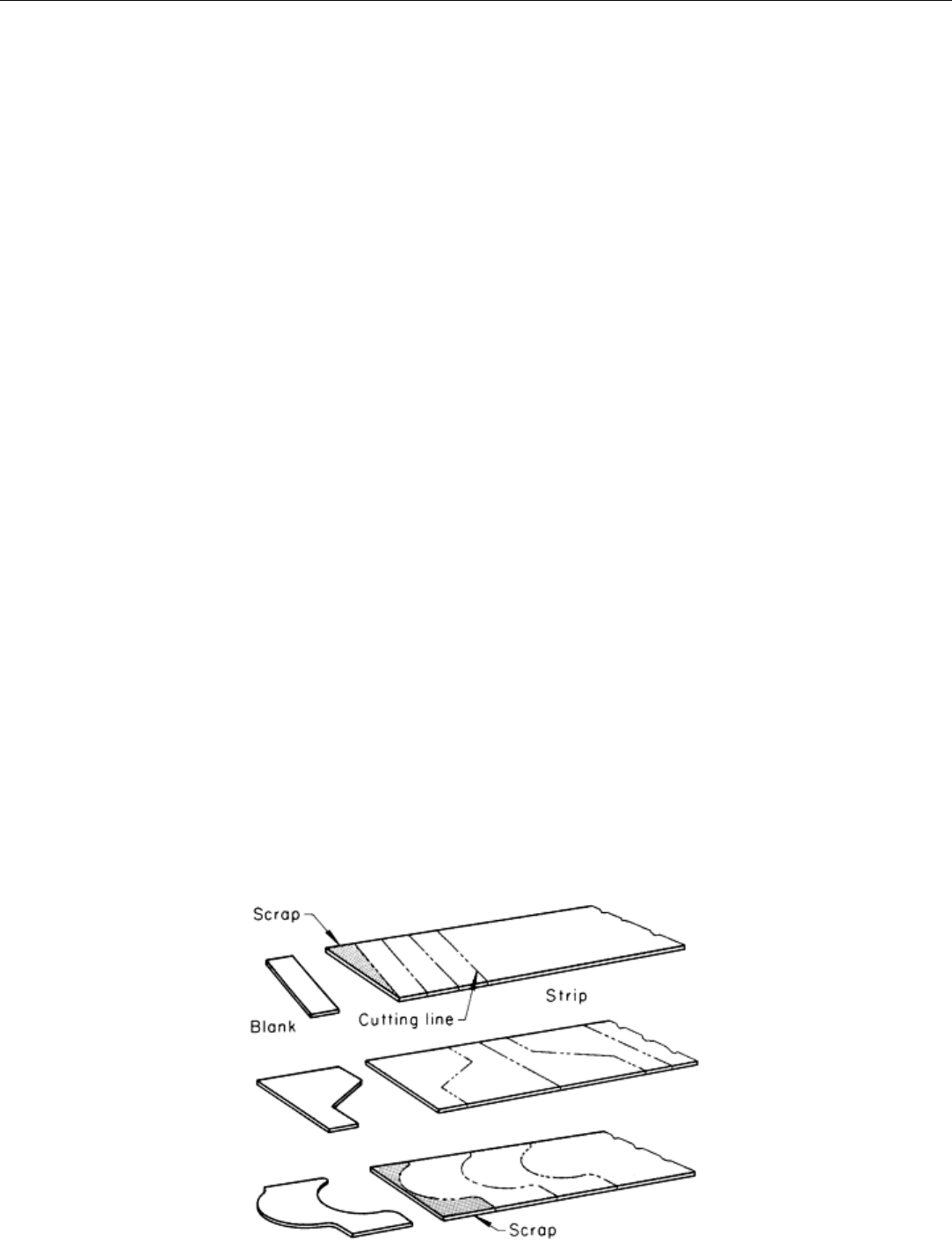
A cutoff die can be used to cut the entire outline of blanks whose shape permits nesting in a layout that uses all of the
material (except possibly at the ends of the strip), as shown in Fig. 1. Alternating positions can sometimes be used in
nesting (middle, Fig. 1) to avoid producing scrap except at strip ends. Cutoff is also used to cut blanks from strip that has
already been notched to separate the blanks along part of their periphery, as described in the following example.
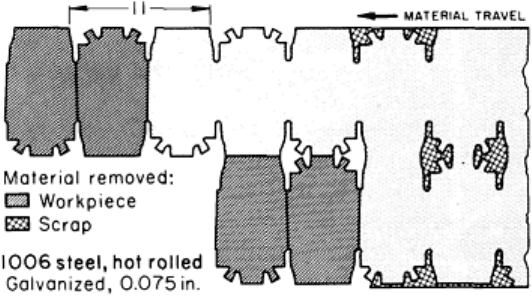
Fig. 1 Nested layouts for making blanks by cutoff
Example 1: Use of Cutoff to Separate Blanks Partly Outlined by Notching.
Figure 2 shows the layout for the cutoff of blanks for automobile body-bolt brackets. The brackets were completed by
piercing and forming.
The coiled strip of galvanized hot-rolled 1006 steel was
1.90 mm (0.075 in.) thick by 495 mm (19.5 in.) wide.
This was wide enough for two blanks, as shown in Fig.
2. The blanks were alternated in the layout to facilitate
trimming and piercing.
The strip was notched and seminotched in the first
stations of a progressive die (making a small amount of
scrap). In the following stations, straight cutoff punches
made four blanks at each stroke without producing any
additional scrap.
The work was done in a 3.6 MN (400 tonf) single-action
mechanical press with an air cushion. The press was
equipped with a double roll feed and made 50 strokes
(200 blanks) per minute.
Advantages of cutoff in making blanks include:
• The die has few components and is relatively inexpensive
• Waste of material in blanking is minimized or eliminated
• The die can be resharpened easily, and maintenance costs are low
Disadvantages of cutoff include:
• It can be used only to make blanks that nest in the layout without waste
• Cutting of one edge causes one-way deflection and stress
• Accuracy may be affected adversely by the method of feeding
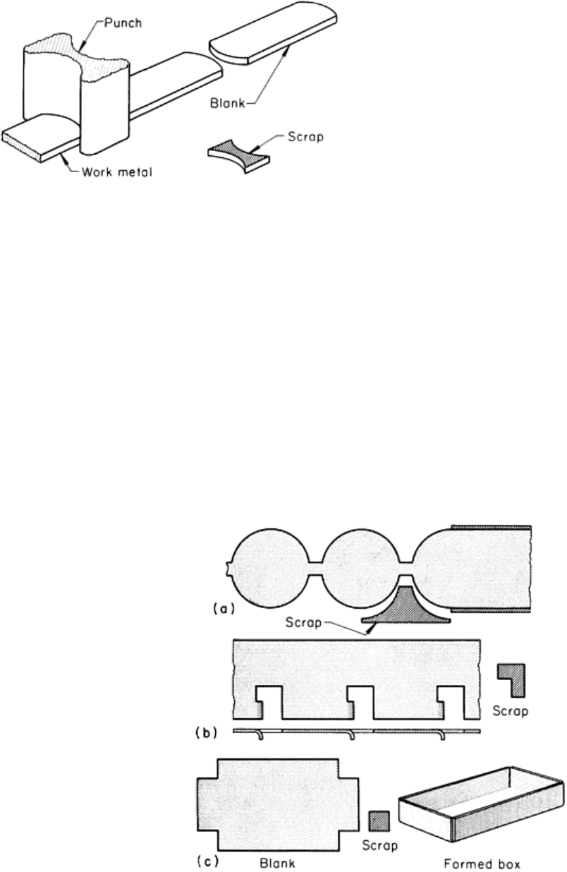
Parting (Fig. 3) is the separation of blanks by cutting away a strip of material between them. Like cutoff, it can be done
after most of the part outline has been developed by notching or lancing. It is used to make blanks that do not have mating
adjacent surfaces for cutoff (Fig. 3) or to make blanks that must be spaced for ease of handling in order to avoid distortion
or to allow room for sturdy tools. Some scrap is produced in making blanks by parting; therefore, this method is less
efficient than cutoff in terms of material use.
Fig. 2
Layout for the cutoff of four blanks at each press
stroke from notched and seminotched strip. Dime
nsions
given in inches
Blanking (also called punching) is the cutting of the
complete outline of a workpiece in a single press stroke.
Because a scrap skeleton is usually produced, blanking
involves some material waste. However, blanking is
usually the fastest and most economical way to make flat
parts, particularly in large quantities.
The skeleton left by blanking sometimes has only scrap-
metal value, but many shops have organized programs to
maximize the use of cutouts and sizable scrap skeletons
in making other production parts. Material waste is
completely avoided by using the scrap skeleton that
remains from certain blanking operations to provide
perforated stock for such items as air filters for forced-
air furnaces.
Piercing (with a flat-end punch), also called punching or perforating, is similar to blanking except that the punched-out
(blanked) slug is the waste and the surrounding metal is the workpiece. Piercing is discussed in the article "Piercing of
Low-Carbon Steel" in this Volume.
Notching is an operation in which the individual punch removes a piece of metal from the edge of the blank or strip
(Fig. 4). Notching is done for such reasons as the following:
• To free some metal for drawing (Fig. 4a) and for forming (Fig. 4
b) while the workpiece remains
attached to the strip
• To remove excess metal before forming (Fig. 4c)
• To cut part of the outline of a blank that would be difficult to cut otherwise (Fig. 2 and Fig. 28)
Fig. 4 Not
ched work illustrating the use of notching for freeing metal before drawing (a), and before forming
(b), and for removing excess metal before forming (c)
The piercing of holes of any shape in a strip to free metal for subsequent forming or to produce surfaces that later
coincide with the outline of a blanked part is sometimes called seminotching. The pierced area may outline a portion of
Fig. 3
Use of a parting punch to make blanks not having
mating adjacent surfaces
one part or of two or more adjacent parts in a strip. Figure 2 illustrates a progressive-die layout incorporating
seminotching.
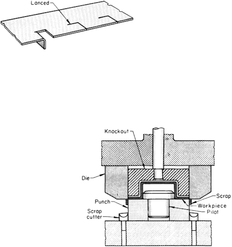
Lancing is a press operation in which a single-line cut or slit is made part way across the strip stock without removing
any metal. Lancing is usually done to free metal for forming (Fig. 5). The cut does not have a closed contour and does not
release a blank or a piece of scrap. In addition to its use in freeing metal for subsequent forming, lancing is also used to
cut partial contours for blanked parts, particularly in progressive dies.
Trimming is an operation for removing excess metal (such
as deformed and uneven metal on drawn or formed parts) and
metal that was used in a previous operation (such as a
blankholding flange for a draw operation). Trimming is done
in several ways, depending on the shape of the workpiece,
the accuracy required, and the production quantity.
Figure 6 illustrates the tooling for trimming a horizontal
flange on a drawn shell in a separate operation. The drawn
shell is set on a locating plug for trimming. After scrap from
a sufficient number of trimmed shells has accumulated, the
piece of scrap at the bottom is severed at each stroke of the
press by the scrap cutters shown in Fig. 6, and falls clear. Except that the die must be constructed to accept and locate the
drawn shell, the operation is identical to the blanking of a flat workpiece and produces square edges of the same accuracy
and quality. A drawn shell or formed part can be trimmed in a press without leaving a flange on the completed part by
using one of three methods: pinch trim, shimmy trim, or trim and wipe-down.
Fig. 6 Single-
operation die for trimming a horizontal
flange on a drawn shell
Pinch trimming, shown as a separate operation in a push-through die in Fig. 7, is done only on a part that has at least a
narrow flange as-formed. The shell must be free from wrinkles at or near the trimming line. The trimmed edge is not
square with the sidewall, but has the general shape shown in the lower right corner of Fig. 7. The accuracy of height
resulting from pinch trimming is affected by variations in wall thickness and flange radius. To ensure an even pinch-off
and to avoid sharp or rough edges, clearance between punch and die must be held to a minimum, and the punch must be
kept sharp.
Fig. 5 Strip that was lanced to free metal for forming
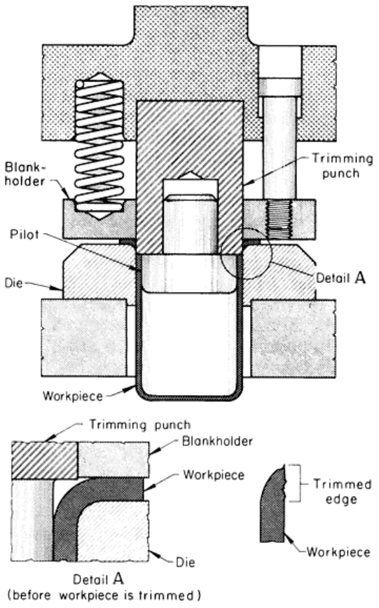
Fig. 7 Pinch trimming a drawn shell in a push-through die
Pinch trimming is also done without a blankholder or hold-down, using a die otherwise similar to that shown in Fig. 7.
The scrap rings can be blown off the die at each stroke. In another method, the scrap rings climb the punch until they are
severed by being compressed against a scrap cutter, after which they are spread apart and allowed to run out along a track
for disposal. Pinch trimming without a blankholder is particularly well suited to the high-volume production of eyelets
and other small parts.
Pinch trimming is primarily a mass production method. The production rate is high because only one stroke of the press is
required to complete the trim. The method is often combined with drawing in a compound draw-and-trim die to reduce
production costs further. The disadvantages of pinch trimming are excessive burrs, sharp cut edge, and high die
maintenance.
Shimmy Trimming. In trimming with a shimmy die (also known as Brehm or model trimming), the drawn shell is held
in a close-fitting die of the exact shell height and trimmed in segments by the successive horizontal oscillations of an
internal cam-actuated punch toward the outside of the shell. The resulting trimmed edge is square and closely resembles
the conventional blanked edge on a flat part. Shell height is more accurate than with pinch trimming. In addition to its
application to shells that must have square, accurate edges, shimmy trimming is used on shells that have a wrinkled or
otherwise nonuniform top edge as-drawn (cutoff is done below the defects) and on shells that cannot be produced
economically with even the narrow flange needed for pinch trimming.
Tooling costs for shimmy trimming are much higher than those for pinch trimming. Shimmy trimming is also slower
because it requires four or more oscillations of the punch in one press stroke and cannot be combined with other
operations in a compound die. Shimmy dies are inexpensive to maintain because they remain in alignment and therefore
are not likely to wear by shearing or chipping.
Trim and Wipe-Down. In this type of trimming, a flange is cut to width using a die such as that shown in Fig. 6 and
then wiped or straightened into line with the sidewall of the shell or formed part. Because of narrow flange width,
trimming and wiping down may be two operations.
The edge is square with the sidewall, but the shell height may be slightly irregular because of the forming characteristics
of the metal. In addition, a ring may be visible at the original location of the flange radius.
Trimming, other than shimmy trimming, is frequently combined with one or more other operations in a compound die.
Trim stock is often left on a drawn or formed workpiece so that it can be trimmed to size in a second operation. This is
done to obtain the most accurate relationship of some other feature, such as a pierced hole, to the trimmed outline of the
workpiece.
Blanking of Low-Carbon Steel
Characteristics of Blanked Edges
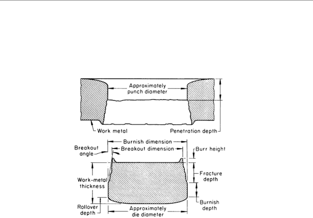
The sheared edges of a blank produced in a conventional die are not smooth and vertical for the entire thickness of the
part, but exhibit the characteristics represented on an exaggerated scale in Fig. 8. The blank is shown in the position in
which it would be cut from the work metal by the downward motion of the punch. A portion of the stock remaining after
removal of the blank is shown at the top of the illustration.
Fig. 8 Characteristics of the sheared edges of a blank. Curvature and angles are exaggerated for emphasis.
Rollover on the lower edges of the blank develops by plastic deformation of the work metal as it is forced into the die by
the punch. Compression of the metal above the rollover zone against the walls of the die opening burnishes a portion of
the edge of the blank, as shown in Fig. 8. As the punch completes its stroke, the remaining portion of the blank edge is
broken away or fractured (resulting in die break), and a tensile burr is formed along the top of the blank edge.
The angle of the fractured portion of the edge is identified in Fig. 8 as the breakout angle. The breakout dimension of the
blank and the burnish dimension of the hole in the scrap skeleton are approximately equal to the corresponding punch

dimension, and the burnish dimension of the blank is very close to the corresponding die dimension. Therefore, the punch
determines the hole size, and the die governs the blank size.
Penetration depth, or the amount of penetration of the punch into the work metal before fracture occurs, is shown on the
edge of the remaining stock or scrap skeleton in Fig. 8. This depth is approximately equal to the sum of the rollover depth
and the burnish depth on the blank, except when low die clearance produces secondary burnish. It is usually expressed as
a percentage of the work metal thickness.
The percentage of penetration (before fracture) depends on the properties of the work metal, as shown in Table 1, which
gives approximate values for various steels and nonferrous metals under typical blanking conditions. The percentage of
penetration affects energy consumption and cutting force in blanking, as described in the section "Calculation of Force
Requirements" in this article.
Table 1 Approximate penetration of sheet thickness before fracture in blanking
Work metal Penetration, %
Carbon steels
(a)
0.10% C, Ann 50
0.10% C, CR 38
0.20% C, Ann 40
0.20% C, CR 28
0.30% C, Ann 33
0.30% C, CR 22
Silicon steels 30
Nonferrous metals
Aluminum alloys
60
Brass 50
Bronze 25
Copper 55
Nickel alloys 55
Zinc alloys 50
(a)
Ann, annealed; CR, cold rolled
Blanking of Low-Carbon Steel
Die Clearance
The terms clearance, die clearance, and punch-to-die clearance are used synonymously to refer to the space between
punch and die. Clearance is important for the reliable operation of the blanking equipment, the quality and type of cut
edges, and the life of the punch and die. In general, the effects of clearance on these factors in blanking are the same as in
piercing and are discussed in the article "Piercing of Low-Carbon Steel" in this Volume. The same article also describes
the edge characteristics of slugs produced in piercing holes (see Fig. 2 of that article). The data in that illustration can
serve as a guide for selecting clearances for blanking. All clearance values given in this article are per side, except where
indicated.
Optimal blanking clearance may sometimes be less than optimal piercing clearance. This is partly because the blanked
edge is generally close to the stock edge, and material expansion is therefore less restricted. A piercing tool must move a
great deal of material away from its cutting edge, and for longest life, the clearance should be selected to eliminate as
much compressive loading on the work metal as possible.
A part blanked using clearance much greater than normal may exhibit double shear, which is ordinarily evident only with
extremely small clearance (see edge types 4 and 5 in Fig. 2 in the article "Piercing of Low-Carbon Steel" in this Volume).
In addition, a part blanked using large clearances will be smaller than the die opening (except for a deeply dished blank),
and it is difficult to correct the tooling to compensate for this. In some applications, retaining the blank becomes almost as
great a problem as expelling the slugs into a die cavity after piercing, because of the increased clearance.
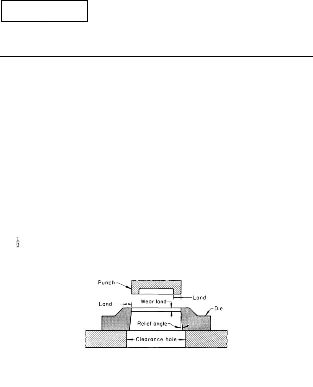
Relief in a blanking die (Fig. 9) is the taper provided so that the severed blank can fall free. The relief angle may range
from to 2° from the vertical wall of the die opening. Relief in a die is sometimes called draft or angular clearance. In
some dies, the relief may start at the top of the die surface and have a taper of only 0.002 in./in. (0.002 mm/mm) per side.
In other dies, there is a straight, vertical wear land between the top of the die and the relief.
Fig. 9 Relief in a blanking die
Blanking of Low-Carbon Steel
Calculation of Force Requirements
Calculation of the forces and the work involved in blanking gives average figures that are applicable only when the
correct shear strength for the material is used and when the die is sharp and the punch is in good condition, has correct

clearance, and is functioning properly. The total load on the press, or the press capacity required to do a particular job, is
the sum of the cutting force and other forces acting at the same time, such as the blankholding force exerted by a die
cushion.
Cutting Force: Square-End Punches and Dies. When punch and die surfaces are flat and at right angles to the
motion of the punch, the cutting force can be found by multiplying the area of the cut section by the shear strength of the
work material:
L = S
s
tl
(Eq 1)
where L is the load on the press (in pounds) (cutting force), S
s
is the shear strength of the stock (in pounds per square
inch), t is the stock thickness (in inches), and l is the length or perimeter of the cut (in inches). The shear strengths of
various steels and nonferrous metals are given in Table 2.
Table 2 Shear strengths of various steels and nonferrous metals at room temperature
Shear strength
Metal
MPa
ksi
Carbon steels
0.10% C
241-296
35-43
0.20% C
303-379
44-55
0.30% C
358-462
52-67
High-strength low-alloy steels
310-439
45-63.7
Silicon steels 414-483
60-70
Stainless steels 393-827
57-129
Nonferrous metals
Aluminum alloys 48-317
7-46
Copper and bronze 152-483
22-70
Lead alloys 13-40
1.83-5.87
Magnesium alloys 117-200
17-29
Nickel alloys 242-800
35-116