Baker R.C. Flow Measurement Handbook: Industrial Designs, Operating Principles, Performance, and Applications
Подождите немного. Документ загружается.

4.2 APPROACHES TO CALIBRATION
67
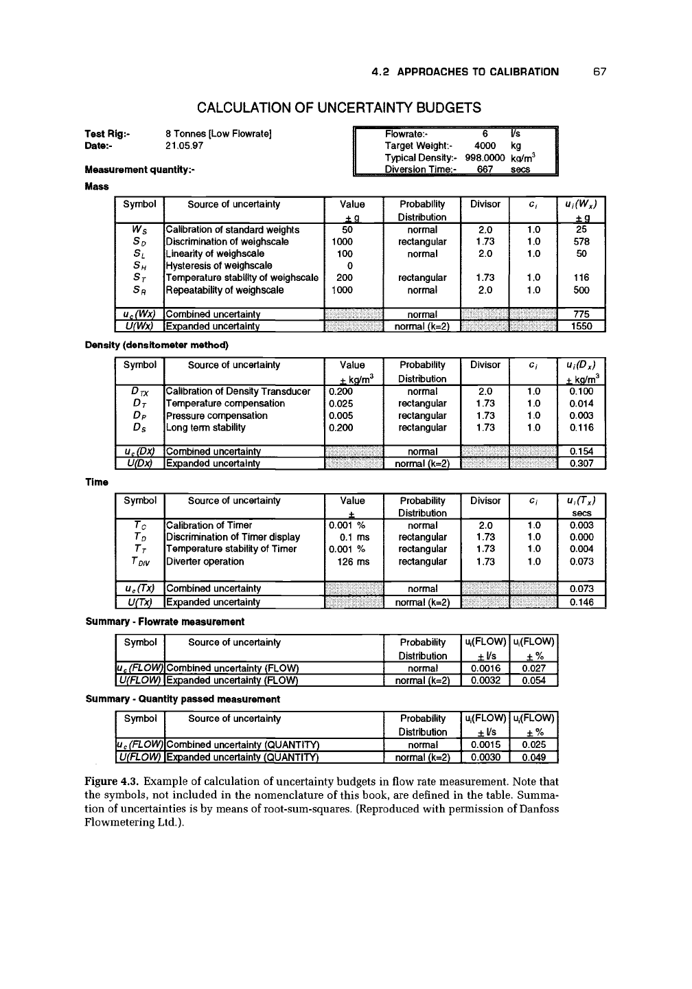
CALCULATION OF UNCERTAINTY BUDGETS
Test Rig:- 8 Tonnes [Low Fiowrate]
Date:-
21.05.97
Measurement quantity:-
Mass
Flowrate:-
Target Weight:-
Typical Density:-
Diversion Time:-
6
4000
998.0000
667
l/s
kg
kp/m
3
sees
Symbol
S°
L
S
H
ST
SR
u
c
(Wx)
U(Wx)
Source of uncertainty
Calibration of standard weights
Discrimination of weighscaie
Linearity of weighscaie
Hysteresis of weighscaie
Temperature stability of weighscaie
Repeatability of weighscaie
Combined uncertainty
Expanded uncertainty
Value
±Q
50
1000
100
0
200
1000
Probability
Distribution
normal
rectangular
normal
rectangular
normal
normal
normal (k=2)
Divisor
2.0
1.73
2.0
1.73
2.0
c
i
1.0
1.0
1.0
1.0
1.0
U;(W
X
)
±g
25
578
50
116
500
775
1550
Density (densitometer method)
Symbol
DTX
DJ
D
P
D
s
u
c
(Dx)
U(Dx)
Source of uncertainty
Calibration of Density Transducer
Temperature compensation
Pressure compensation
Long term stability
Combined uncertainty
Expanded uncertainty
Value
±kq/m
3
0.200
0.025
0.005
0.200
Probability
Distribution
normal
rectangular
rectangular
rectangular
normal
normal (k=2)
Divisor
2.0
1.73
1.73
1.73
Ci
1.0
1.0
1.0
1.0
Ui(D
x
)
±ko/rn
3
0.100
0.014
0.003
0.116
0.154
0.307
Time
Symbol
To
T
D
T
T
T~DIV
u
c
(Tx)
U(Tx)
Source of uncertainty
Calibration of Timer
Discrimination of Timer display
Temperature stability of Timer
Diverter operation
Combined uncertainty
Expanded uncertainty
Value
±
0.001 %
0.1 ms
0.001 %
126 ms
Probability
Distribution
normal
rectangular
rectangular
rectangular
normal
normal (k=2)
Divisor
2.0
1.73
1.73
1.73
C\
1.0
1.0
1.0
1.0
u,(T
x
)
sees
0.003
0.000
0.004
0.073
0.073
0.146
Summary - Fiowrate measurement
Symbol
u
c
(FLOWl
U(FLOW)
Source of uncertainty
Combined uncertainty (FLOW)
Expanded uncertainty (FLOW)
Probability
Distribution
normal
normal (k=2)
Uj(FLOW)
±l/s
0.0016
0.0032
Ui(FLOW)
±%
0.027
0.054
Summary
-
Quantity passed measurement
Symbol
u
c
(FLOW)
U(FLOW)
Source
of
uncertainty
Combined uncertainty (QUANTITY)
Expanded uncertainty (QUANTITY)
Probability
Distribution
normal
normal
(k=2)
Uj(FLOW)
±l/s
0.0015
0.0030
Uj(FLOW)
±%
0.025
0.049
Figure 4.3. Example of calculation of uncertainty budgets in flow rate measurement. Note that
the symbols, not included in the nomenclature of this book, are defined in the table. Summa-
tion of uncertainties is by means of root-sum-squares. (Reproduced with permission of Danfoss
Flowmetering Ltd.).
68
CALIBRATION
MASS
DENSITY
TIME
NPL
Stainless steel
Ref, weight STI/831596
Ref. setSTI/831310
Ref. setSTi/852248-860416
South Yorkshire
Trading Standards
NAMAS Laboratory
Measurement uncertainty
+/- 50g/tonne
Cast iron
1000kg weights
DANFOSS
collecting tank
Combined uncertainty
for
MASS measurement
+/-0.02%
NPL
NPL
i i
Schlumberger Industries
NAMAS Laboratory
Measurement uncertainty
+/-
0.2
kg/m.3
Schlumberger 7830B
Density transducer
DANFOSS
Densitometer
Combined uncertainty
for
DENSITY measurement
+/- 0.03%
DANFOSS
gravimetric flow
rig
Combined uncertainty
for
measurement
of
QUANTITY PASSED
Electroservices
(Instruments)
Ltd
NAMAS Laboratory
Measurement uncertainty
+/-1
part
in 10
8
Philips PM6669
Timer/counter
DANFOSS
Diversion timer
Combined uncertainty
for
TIME measurement
+/- 0.02%
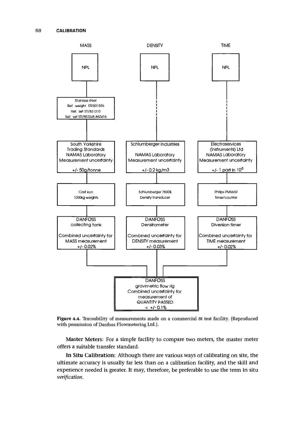
Figure
4.4.
Traceability
of
measurements made
on a
commercial
8t
test facility. (Reproduced
with permission
of
Danfoss Flowmetering Ltd.).
Master Meters: For a simple facility to compare two meters, the master meter
offers a suitable transfer standard.
In Situ Calibration: Although there are various ways of calibrating on site, the
ultimate accuracy is usually far less than on a calibration facility, and the skill and
experience needed is greater. It may, therefore, be preferable to use the term in situ
verification.
4.3 LIQUID CALIBRATION FACILITIES 69
Dry Calibration: Dry calibration is not strictly calibration. An orifice meter, if
correctly constructed according to the standards, can be measured, and from the
measurements it should be possible to deduce the flow for a particular pressure
drop.
The same is true of other standard meters such as the venturi, nozzle, and
critical flow venturi nozzle. Other meters are less predictable. No flow test is used,
and so dry
calibration
is something of a misnomer, since we are really talking about
the ability of standards or theory to predict performance. The reader is referred to
the appropriate chapter for the likely predictability of particular flowmeters such
as the electromagnetic and ultrasonic.
4.3 LIQUID CALIBRATION FACILITIES
4.3.1 FLYING START AND STOP
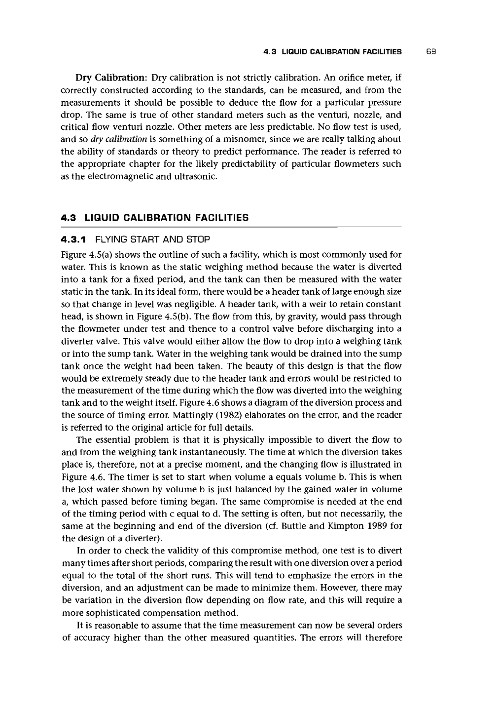
Figure 4.5(a) shows the outline of such a facility, which is most commonly used for
water. This is known as the static weighing method because the water is diverted
into a tank for a fixed period, and the tank can then be measured with the water
static in the tank. In its ideal form, there would be a header tank of large enough size
so that change in level was negligible.
A
header tank, with a weir to retain constant
head, is shown in Figure 4.5(b). The flow from this, by gravity, would pass through
the flowmeter under test and thence to a control valve before discharging into a
diverter valve. This valve would either allow the flow to drop into a weighing tank
or into the sump tank. Water in the weighing tank would be drained into the sump
tank once the weight had been taken. The beauty of this design is that the flow
would be extremely steady due to the header tank and errors would be restricted to
the measurement of the time during which the flow was diverted into the weighing
tank and to the weight
itself.
Figure 4.6 shows a diagram of the diversion process and
the source of timing error. Mattingly (1982) elaborates on the error, and the reader
is referred to the original article for full details.
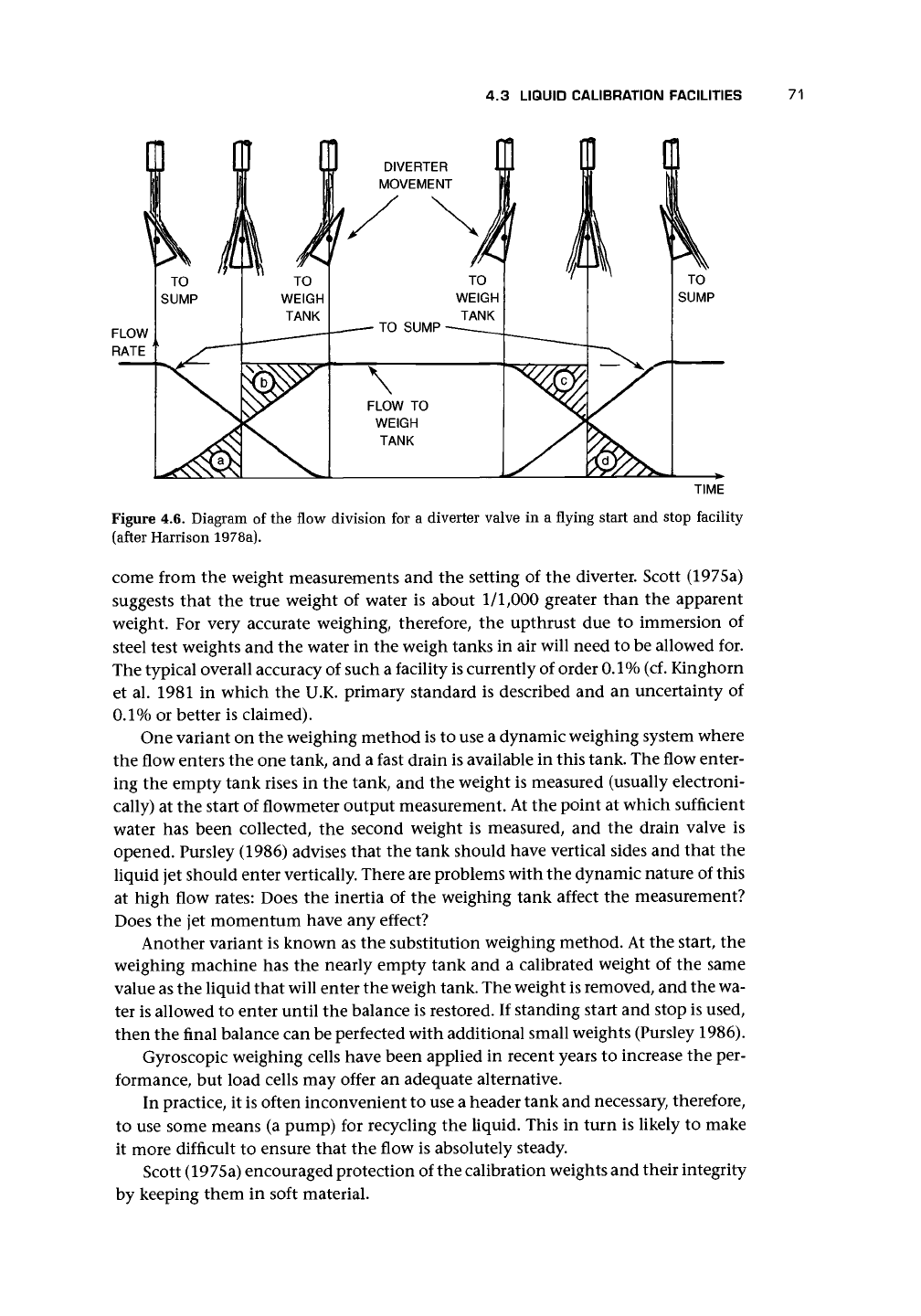
The essential problem is that it is physically impossible to divert the flow to
and from the weighing tank instantaneously. The time at which the diversion takes
place is, therefore, not at a precise moment, and the changing flow is illustrated in
Figure 4.6. The timer is set to start when volume a equals volume b. This is when
the lost water shown by volume b is just balanced by the gained water in volume
a, which passed before timing began. The same compromise is needed at the end
of the timing period with c equal to d. The setting is often, but not necessarily, the
same at the beginning and end of the diversion (cf. Buttle and Kimpton 1989 for
the design of a diverter).
In order to check the validity of this compromise method, one test is to divert
many times after short periods, comparing the result with one diversion over
a
period
equal to the total of the short runs. This will tend to emphasize the errors in the
diversion, and an adjustment can be made to minimize them. However, there may
be variation in the diversion flow depending on flow rate, and this will require a
more sophisticated compensation method.
It is reasonable to assume that the time measurement can now be several orders
of accuracy higher than the other measured quantities. The errors will therefore
70
CALIBRATION
HEADER
TANK
OVER FLOW
LINE
CALMING
BAFFLES
CONTROL
VALVE
FLOWMETER
UNDER
TEST
DIVERTER
VALVE
(a)
CALMING
BAFFLES
OVER FLOW
TO SUMP
TO CALIBRATION
LINE
(b)
FROM
SUMP
Figure 4.5. Flying start and stop liquid flow calibration facility with static weighing: (a) Outline
diagram; (b) Typical constant head tank design (after Harrison 1978a).
4.3 LIQUID CALIBRATION FACILITIES
71
TIME
Figure 4.6. Diagram of the flow division for a diverter valve in a flying start and stop facility
(after Harrison 1978a).
come from the weight measurements and the setting of the diverter. Scott (1975a)
suggests that the true weight of water is about
1/1,000
greater than the apparent
weight. For very accurate weighing, therefore, the upthrust due to immersion of
steel test weights and the water in the weigh tanks in air will need to be allowed for.
The typical overall accuracy of such a facility is currently of order
0.1%
(cf. Kinghorn
et al. 1981 in which the U.K. primary standard is described and an uncertainty of
0.1%
or better is claimed).
One variant on the weighing method is to use a dynamic weighing system where
the flow enters the one tank, and a fast drain is available in this tank. The flow enter-
ing the empty tank rises in the tank, and the weight is measured (usually electroni-
cally) at the start of flowmeter output measurement. At the point at which sufficient
water has been collected, the second weight is measured, and the drain valve is
opened. Pursley (1986) advises that the tank should have vertical sides and that the
liquid jet should enter vertically. There are problems with the dynamic nature of this
at high flow rates: Does the inertia of the weighing tank affect the measurement?
Does the jet momentum have any effect?
Another variant is known as the substitution weighing method. At the start, the
weighing machine has the nearly empty tank and a calibrated weight of the same
value as the liquid that will enter the weigh tank. The weight is removed, and the wa-
ter is allowed to enter until the balance is restored. If standing start and stop is used,
then the final balance can be perfected with additional small weights (Pursley 1986).
Gyroscopic weighing cells have been applied in recent years to increase the per-
formance, but load cells may offer an adequate alternative.
In practice, it is often inconvenient to use a header tank and necessary, therefore,
to use some means (a pump) for recycling the liquid. This in turn is likely to make
it more difficult to ensure that the flow is absolutely steady.
Scott (1975a) encouraged protection of the calibration weights and their integrity
by keeping them in soft material.
72
CALIBRATION
4.3.2 STANDING START AND STOP
The standing start and stop amounts to allowing fluid to pass through the meter for
a fixed time and then comparing the total registered by a reference meter with the
amount collected. The amount collected could be measured either as a volume or a
weight. The problem with this method is that the meter must follow the changing
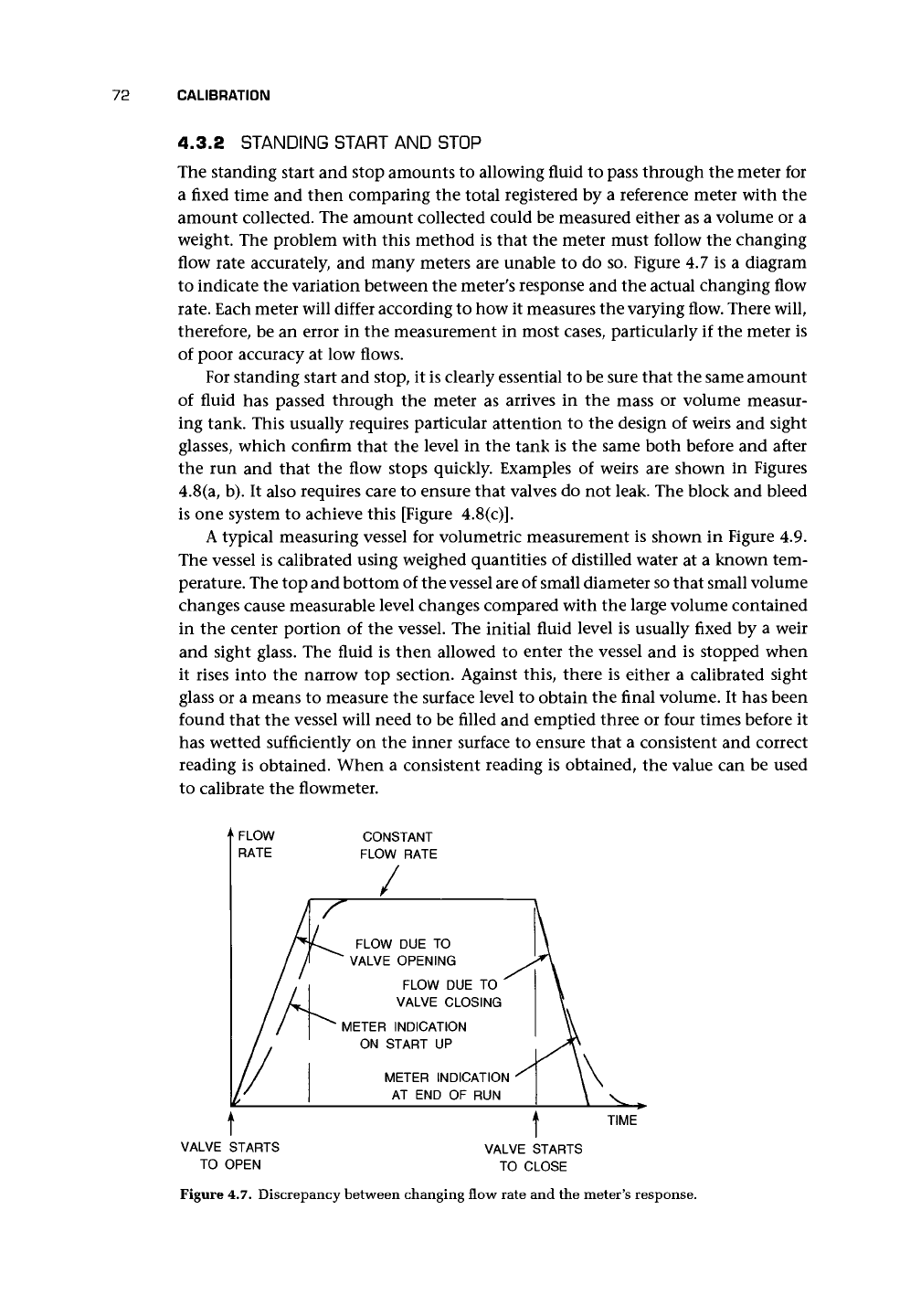
flow rate accurately, and many meters are unable to do so. Figure 4.7 is a diagram
to indicate the variation between the meter's response and the actual changing flow
rate.
Each meter will differ according to how it measures the varying flow. There will,
therefore, be an error in the measurement in most cases, particularly if the meter is
of poor accuracy at low flows.
For standing start and stop, it is clearly essential to be sure that the same amount
of fluid has passed through the meter as arrives in the mass or volume measur-
ing tank. This usually requires particular attention to the design of weirs and sight
glasses, which confirm that the level in the tank is the same both before and after
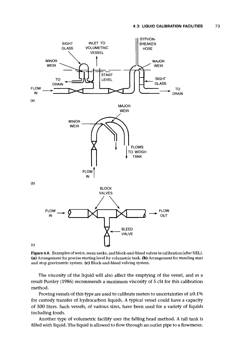
the run and that the flow stops quickly. Examples of weirs are shown in Figures
4.8(a, b). It also requires care to ensure that valves do not leak. The block and bleed
is one system to achieve this [Figure 4.8(c)].
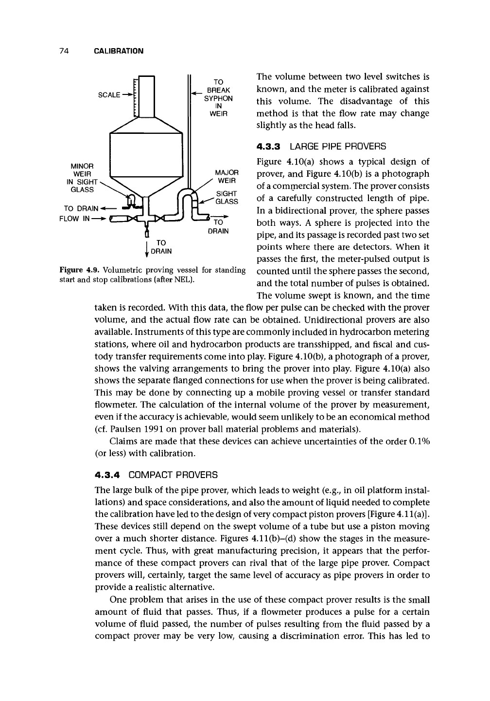
A typical measuring vessel for volumetric measurement is shown in Figure 4.9.
The vessel is calibrated using weighed quantities of distilled water at a known tem-
perature. The top and bottom of the vessel are of small diameter so that small volume
changes cause measurable level changes compared with the large volume contained
in the center portion of the vessel. The initial fluid level is usually fixed by a weir
and sight glass. The fluid is then allowed to enter the vessel and is stopped when
it rises into the narrow top section. Against this, there is either a calibrated sight
glass or a means to measure the surface level to obtain the final volume. It has been
found that the vessel will need to be filled and emptied three or four times before it
has wetted sufficiently on the inner surface to ensure that a consistent and correct
reading is obtained. When a consistent reading is obtained, the value can be used
to calibrate the flowmeter.
FLOW
RATE
/
A
1
/A
1
/
i/
CONSTANT
FLOW RATE
r
U^^ FLOW DUE TO
VALVE OPENING ^
FLOW DUE TO
VALVE CLOSING
^ METER INDICATION
ON START UP
METER INDICATION '
AT END OF RUN
t
\
\
\
\
v
\
TIME
VALVE STARTS
TO OPEN
VALVE STARTS
TO CLOSE
Figure 4.7. Discrepancy between changing flow rate and the meter's response.
4.3 LIQUID CALIBRATION FACILITIES
73
SIGHT
GLASS
INLET TO
VOLUMETRIC
VESSEL
MINOR
WEIR
SYPHON-
BREAKER
HOSE
MAJOR
WEIR
SIGHT
GLASS
TO
DRAIN
(a)
FLOWS
TO WEIGH
TANK
(b)
FLOW
IN
FLOW
OUT
(c)
Figure
4.8.
Examples of
weirs,
swan
necks,
and block-and-bleed valves in calibration (after
NEL).
(a) Arrangement for precise starting level for volumetric tank, (b) Arrangement for standing start
and stop gravimetric system, (c) Block-and-bleed valving system.
The viscosity of the liquid will also affect the emptying of the vessel, and as a
result Pursley (1986) recommends a maximum viscosity of 5 cSt for this calibration
method.
Proving vessels of this type are used to calibrate meters to uncertainties of
±0.1%
for custody transfer of hydrocarbon liquids. A typical vessel could have a capacity
of 500 liters. Such vessels, of various sizes, have been used for a variety of liquids
including foods.
Another type of volumetric facility uses the falling head method. A tall tank is
filled with liquid. The liquid is allowed to flow through an outlet pipe to a flowmeter.
74
CALIBRATION
SCALE -*•
TO
BREAK
SYPHON
IN
WEIR
MAJOR
WEIR
SIGHT
GLASS
TO
DRAIN
Figure 4.9. Volumetric proving vessel for standing
start and stop calibrations (after NEL).
The volume between two level switches is
known, and the meter is calibrated against
this volume. The disadvantage of this
method is that the flow rate may change
slightly as the head falls.
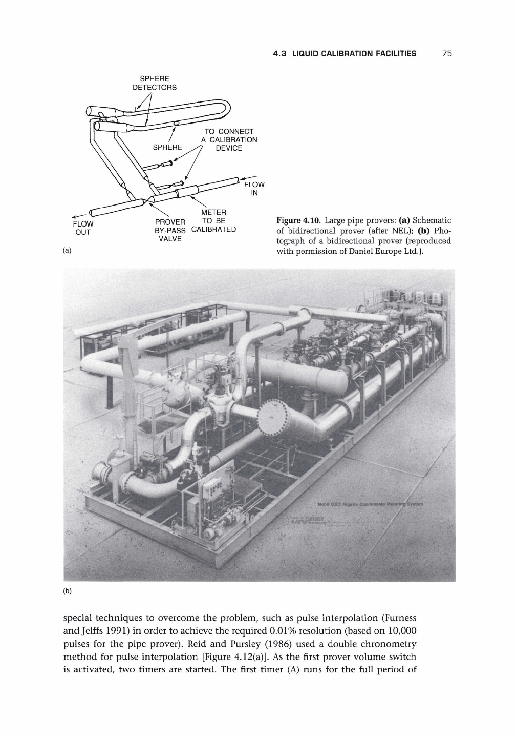
4.3.3 LARGE PIPE PROVERS
Figure 4.10(a) shows a typical design of
prover, and Figure 4.10(b) is a photograph
of
a
commercial system. The prover consists
of a carefully constructed length of pipe.
In a bidirectional prover, the sphere passes
both ways. A sphere is projected into the
pipe,
and its passage is recorded past two set
points where there are detectors. When it
passes the first, the meter-pulsed output is
counted until the sphere passes the second,
and the total number of pulses is obtained.
The volume swept is known, and the time
taken is recorded. With this data, the flow per pulse can be checked with the prover
volume, and the actual flow rate can be obtained. Unidirectional provers are also
available. Instruments of this type are commonly included in hydrocarbon metering
stations, where oil and hydrocarbon products are transshipped, and fiscal and cus-
tody transfer requirements come into play. Figure 4.10(b), a photograph of a prover,
shows the valving arrangements to bring the prover into play. Figure 4.10(a) also
shows the separate flanged connections for use when the prover is being calibrated.
This may be done by connecting up a mobile proving vessel or transfer standard
flowmeter. The calculation of the internal volume of the prover by measurement,
even if the accuracy is achievable, would seem unlikely to be an economical method
(cf. Paulsen 1991 on prover ball material problems and materials).
Claims are made that these devices can achieve uncertainties of the order 0.1%
(or less) with calibration.
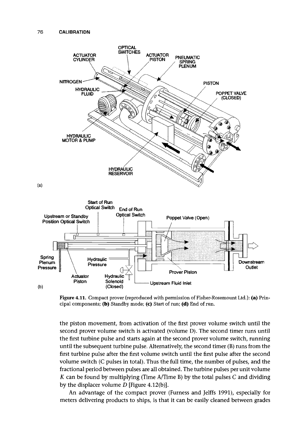
4.3.4 COMPACT PROVERS
The large bulk of the pipe prover, which leads to weight (e.g., in oil platform instal-
lations) and space considerations, and also the amount of liquid needed to complete
the calibration have led to the design of very compact piston provers [Figure 4.11
(a)].
These devices still depend on the swept volume of a tube but use a piston moving
over a much shorter distance. Figures 4.11(b)-(d) show the stages in the measure-
ment cycle. Thus, with great manufacturing precision, it appears that the perfor-
mance of these compact provers can rival that of the large pipe prover. Compact
provers will, certainly, target the same level of accuracy as pipe provers in order to
provide a realistic alternative.
One problem that arises in the use of these compact prover results is the small
amount of fluid that passes. Thus, if a flowmeter produces a pulse for a certain
volume of fluid passed, the number of pulses resulting from the fluid passed by a
compact prover may be very low, causing a discrimination error. This has led to
4.3 LIQUID CALIBRATION FACILITIES 75
SPHERE
DETECTORS
TO CONNECT
A CALIBRATION
DEVICE
FLOW
IN
FLOW
OUT
METER
PROVER
TO BE
BY-PASS CALIBRATED
VALVE
(a)
Figure 4.10. Large pipe provers:
(a)
Schematic
of bidirectional prover (after NEL);
(b) Pho-
tograph
of a
bidirectional prover (reproduced
with permission of Daniel Europe Ltd.).
Mobil OSO Nigeria Coodftnsaifl Meiering Sy«t«m
(b)
special techniques
to
overcome
the
problem, such
as
pulse interpolation (Furness
and Jelffs 1991)
in
order
to
achieve
the
required 0.01% resolution (based
on
10,000
pulses
for the
pipe prover). Reid
and
Pursley (1986) used
a
double chronometry
method
for
pulse interpolation [Figure 4.12(a)].
As the
first prover volume switch
is activated,
two
timers
are
started.
The
first timer
(A)
runs
for the
full period
of
76 CALIBRATION
ACTUATOR
CYLINDER
NITROGEN
HYDRAULIC
FLUID
HYDRAULIC
MOTOR & PUMP
OPTICAL
SWITCHES
ACTUATOR
PISTON
PNEUMATIC
SPRING
PLENUM
PISTON
/
POPPET VALVE
(CLOSED)
(a)
HYDRAULIC
RESERVOIR
Start of Run
Optical Switch
EndofRun
Upstream or Standby
Position Optical Switch
Optical Switch
Poppet Valve (Open)
Spring
Plenum
Pressure
(b)
Downstream
Outlet
Actuator
Piston
Hydraulic
Solenoid
(Closed)
Prover Piston
- Upstream Fluid Inlet
Figure 4.11. Compact prover (reproduced with permission of Fisher-Rosemount
Ltd.):
(a) Prin-
cipal components; (b) Standby mode; (c) Start of run; (d) End of run.
the piston movement, from activation of the first prover volume switch until the
second prover volume switch is activated (volume D). The second timer runs until
the first turbine pulse and starts again at the second prover volume switch, running
until the subsequent turbine pulse. Alternatively, the second timer (B) runs from the
first turbine pulse after the first volume switch until the first pulse after the second
volume switch (C pulses in total). Thus the full time, the number of pulses, and the
fractional period between pulses are all obtained. The turbine pulses per unit volume
K can be found by multiplying (Time A/Time B) by the total pulses C and dividing
by the displacer volume D [Figure 4.12(b)].
An advantage of the compact prover (Furness and Jelffs 1991), especially for
meters delivering products to ships, is that it can be easily cleaned between grades