Baker R.C. Flow Measurement Handbook: Industrial Designs, Operating Principles, Performance, and Applications
Подождите немного. Документ загружается.

13.2 TRANSIT-TIME FLOWMETERS
317
Downstream
pulse
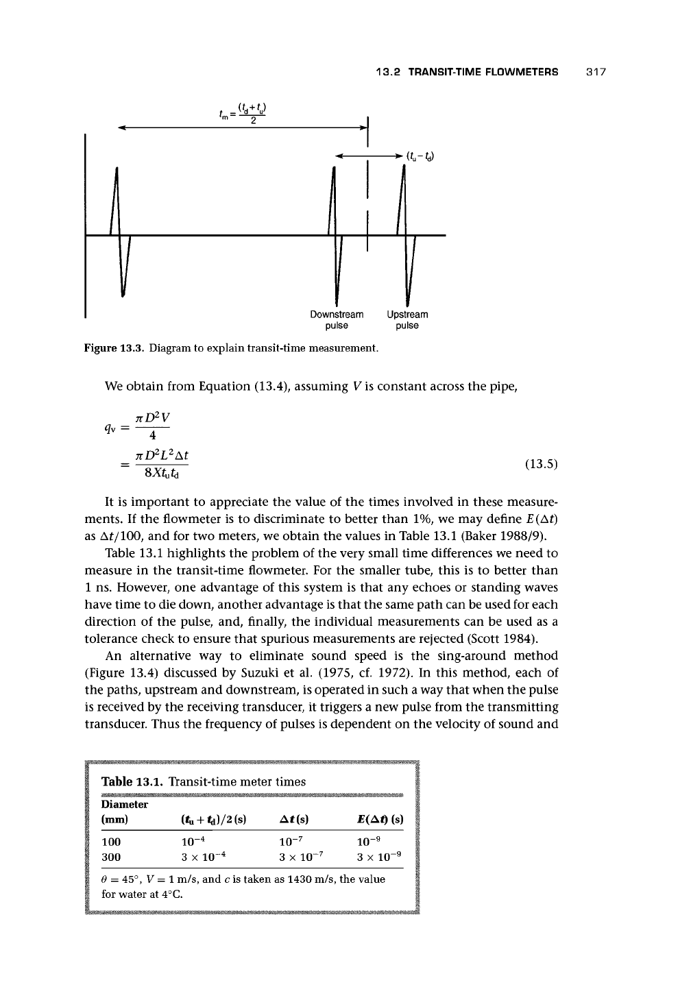
Figure 13.3. Diagram to explain transit-time measurement.
Upstream
pulse
We obtain from Equation (13.4), assuming V is constant across the pipe,
_ nD
2
V
4
7tD
2
L
2
At
(13.5)
It is important to appreciate the value of the times involved in these measure-
ments. If the flowmeter is to discriminate to better than 1%, we may define E(Af)
as At/100, and for two meters, we obtain the values in Table 13.1 (Baker 1988/9).
Table 13.1 highlights the problem of the very small time differences we need to
measure in the transit-time flowmeter. For the smaller tube, this is to better than
1 ns. However, one advantage of this system is that any echoes or standing waves
have time to die down, another advantage is that the same path can be used for each
direction of the pulse, and, finally, the individual measurements can be used as a
tolerance check to ensure that spurious measurements are rejected (Scott 1984).
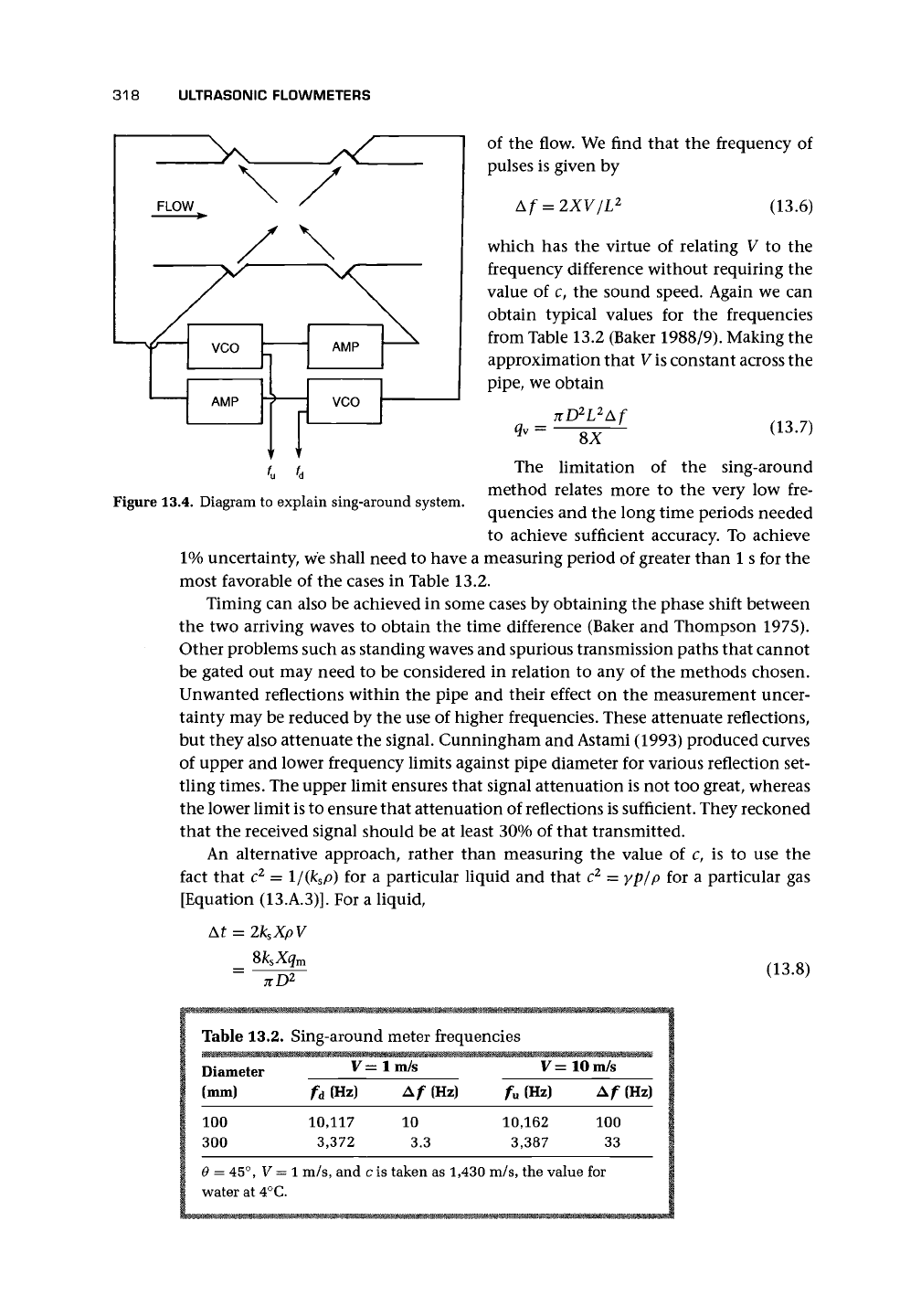
An alternative way to eliminate sound speed is the sing-around method
(Figure 13.4) discussed by Suzuki et al. (1975, cf. 1972). In this method, each of
the paths, upstream and downstream, is operated in such a way that when the pulse
is received by the receiving transducer, it triggers a new pulse from the transmitting
transducer. Thus the frequency of pulses is dependent on the velocity of sound and
Table 13.1.
Diameter
(mm)
100
300
Transit-time meter times
(*U
+ <d)/2 (s) At(s)
io-
4
io-
7
3 x 10~
4
3 x IO-
7
E(At) (s)
io-
9
3 x IO-
9
6 = 45°, V = 1 m/s, and c is taken as 1430 m/s, the value
for water at 4°C.
318 ULTRASONIC FLOWMETERS
of the flow. We find that the frequency of
pulses is given by
=
2XV/L
2
(13.6)
which has the virtue of relating V to the
frequency difference without requiring the
value of c, the sound speed. Again we can
obtain typical values for the frequencies
from Table 13.2 (Baker 1988/9). Making the
approximation that V
is
constant across the
pipe,
we obtain
nD
2
L
2
Af
SX
(13.7)
Figure 13.4. Diagram
to
explain sing-around system.
The limitation of the sing-around
method relates more to the very low fre-
quencies and the long time periods needed
to achieve sufficient accuracy. To achieve
1% uncertainty, we shall need to have a measuring period of greater than 1 s for the
most favorable of the cases in Table 13.2.
Timing can also be achieved in some cases by obtaining the phase shift between
the two arriving waves to obtain the time difference (Baker and Thompson 1975).
Other problems such as standing waves and spurious transmission paths that cannot
be gated out may need to be considered in relation to any of the methods chosen.
Unwanted reflections within the pipe and their effect on the measurement uncer-
tainty may be reduced by the use of higher frequencies. These attenuate reflections,
but they also attenuate the signal. Cunningham and Astami (1993) produced curves
of upper and lower frequency limits against pipe diameter for various reflection set-
tling times. The upper limit ensures that signal attenuation is not too great, whereas
the lower limit is to ensure that attenuation of reflections is sufficient. They reckoned
that the received signal should be at least 30% of that transmitted.
An alternative approach, rather than measuring the value of c, is to use the
fact that c
2
= l/(k
s
p) for a particular liquid and that c
2
= yp/p for a particular gas
[Equation (13.A.3)]. For a liquid,
2k
s
XpV
Sk
s
Xq
m
7ZD
2
(13.8)
Table 13.2. Sing-around meter frequencies
Diameter V=lm/s V=10m/s
(mm)
100
300
e
=
45°,
water
at
V =
4°C.
fd
10,
3,
1
m/s
(Hz)
117
372
,
and
Af (Hz)
10
3.3
cis taken
as 1,430
fu (Hz)
10,162
3,387
m/s,
the value
100
33
for
(Hz)
13.2 TRANSIT-TIME FLOWMETERS 319
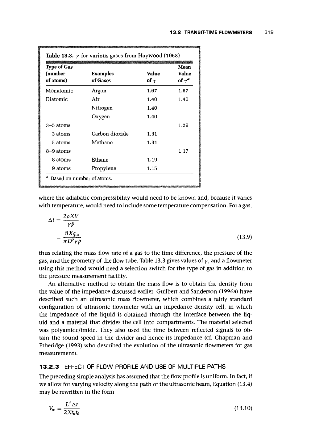
Table 13.3. y for various gases from Haywood (1968)
Type of Gas Mean
(number Examples Value Value
of
atoms)
of
Gases
of 7 of7
fl
1
1
!
I
|
t
1
1
I
v
!
t*
Monatomic
Diatomic
3-5 atoms
3 atoms
5 atoms
8-9 atoms
8 atoms
9 atoms
Argon
Air
Nitrogen
Oxygen
Carbon dioxide
Methane
Ethane
Propylene
a
Based on number of atoms.
1.67
1.40
1.40
1.40
1.31
1.31
1.19
1.15
1.67
1.40
1.29
1.17
where the adiabatic compressibility would need to be known and, because it varies
with temperature, would need to include some temperature compensation. For a gas,
A
^ 2pXV
yp
$Xq
m
nD
2
yp
(13.9)
thus relating the mass flow rate of a gas to the time difference, the pressure of the
gas,
and the geometry of the flow tube. Table 13.3 gives values of y, and a flowmeter
using this method would need a selection switch for the type of gas in addition to
the pressure measurement facility.
An alternative method to obtain the mass flow is to obtain the density from
the value of the impedance discussed earlier. Guilbert and Sanderson (1996a) have
described such an ultrasonic mass flowmeter, which combines a fairly standard
configuration of ultrasonic flowmeter with an impedance density cell, in which
the impedance of the liquid is obtained through the interface between the liq-
uid and a material that divides the cell into compartments. The material selected
was polyamide/imide. They also used the time between reflected signals to ob-
tain the sound speed in the divider and hence its impedance (cf. Chapman and
Etheridge (1993) who described the evolution of the ultrasonic flowmeters for gas
measurement).
13.2.3 EFFECT OF FLOW PROFILE AND USE OF MULTIPLE PATHS
The preceding simple analysis has assumed that the flow profile is uniform. In fact, if
we allow for varying velocity along the path of the ultrasonic beam, Equation (13.4)
may be rewritten in the form
L
2
At
2Xt
u
t
d
(13.10)
320
ULTRASONIC FLOWMETERS
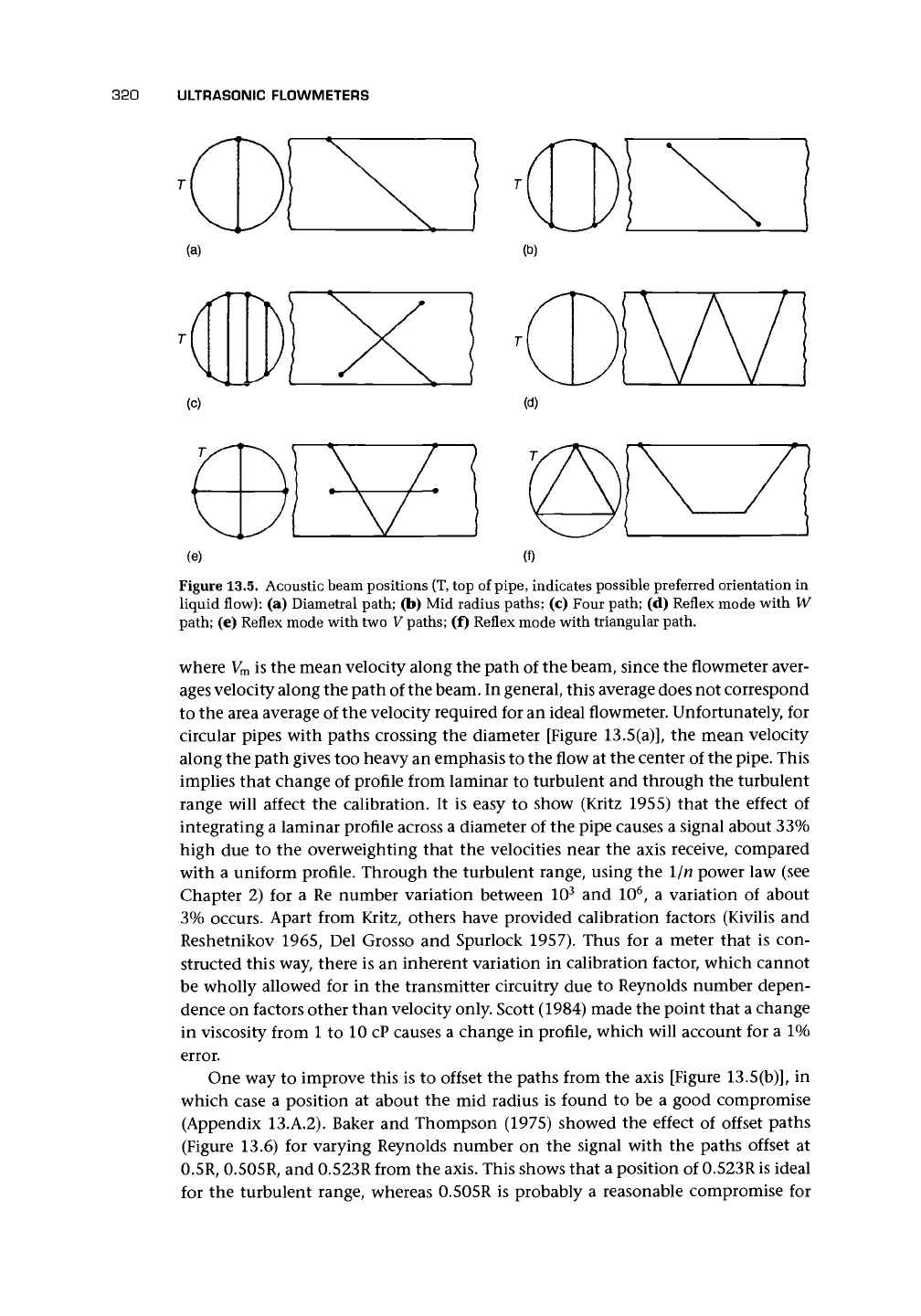
Figure 13.5. Acoustic beam positions
(T,
top of
pipe,
indicates possible preferred orientation in
liquid flow): (a) Diametral path; (b) Mid radius paths; (c) Four path; (d) Reflex mode with W
path; (e) Reflex mode with two V paths; (f) Reflex mode with triangular path.
where V
m
is the mean velocity along the path of the beam, since the flowmeter aver-
ages velocity along the path of the beam. In general, this average does not correspond
to the area average of the velocity required for an ideal flowmeter. Unfortunately, for
circular pipes with paths crossing the diameter [Figure 13.5(a)], the mean velocity
along the path gives too heavy an emphasis to the flow at the center of the pipe. This
implies that change of profile from laminar to turbulent and through the turbulent
range will affect the calibration. It is easy to show (Kritz 1955) that the effect of
integrating a laminar profile across a diameter of the pipe causes a signal about 33%
high due to the overweighting that the velocities near the axis receive, compared
with a uniform profile. Through the turbulent range, using the 1/n power law (see
Chapter 2) for a Re number variation between 10
3
and 10
6
, a variation of about
3%
occurs. Apart from Kritz, others have provided calibration factors (Kivilis and
Reshetnikov 1965, Del Grosso and Spurlock 1957). Thus for a meter that is con-
structed this way, there is an inherent variation in calibration factor, which cannot
be wholly allowed for in the transmitter circuitry due to Reynolds number depen-
dence on factors other than velocity only. Scott (1984) made the point that a change
in viscosity from 1 to 10 cP causes a change in profile, which will account for a 1%
error.
One way to improve this is to offset the paths from the axis [Figure 13.5(b)], in
which case a position at about the mid radius is found to be a good compromise
(Appendix 13.A.2). Baker and Thompson (1975) showed the effect of offset paths
(Figure 13.6) for varying Reynolds number on the signal with the paths offset at
0.5R, 0.505R, and 0.523R from the axis. This shows that a position of 0.523R is ideal
for the turbulent range, whereas 0.505R is probably a reasonable compromise for
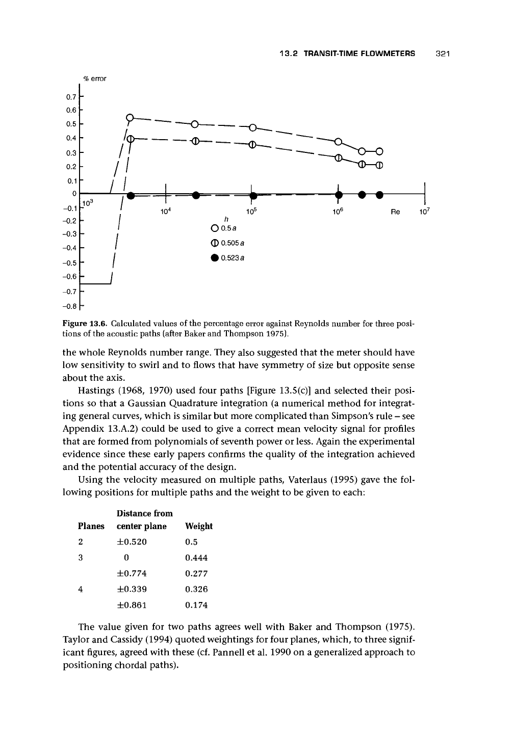
13.2 TRANSIT-TIME FLOWMETERS 321
%
error
Figure 13.6. Calculated values of the percentage error against Reynolds number for three posi-
tions of the acoustic paths (after Baker and Thompson 1975).
the whole Reynolds number range. They also suggested that the meter should have
low sensitivity to swirl and to flows that have symmetry of size but opposite sense
about the axis.
Hastings (1968, 1970) used four paths [Figure 13.5(c)] and selected their posi-
tions so that a Gaussian Quadrature integration (a numerical method for integrat-
ing general curves, which is similar but more complicated than Simpson's rule - see
Appendix 13.A.2) could be used to give a correct mean velocity signal for profiles
that are formed from polynomials of seventh power or less. Again the experimental
evidence since these early papers confirms the quality of the integration achieved
and the potential accuracy of the design.
Using the velocity measured on multiple paths, Vaterlaus (1995) gave the fol-
lowing positions for multiple paths and the weight to be given to each:
Planes
2
3
4
Distance from
center plane
±0.520
0
±0.774
±0.339
±0.861
Weight
0.5
0.444
0.277
0.326
0.174
The value given for two paths agrees well with Baker and Thompson (1975).
Taylor and Cassidy (1994) quoted weightings for four planes, which, to three
signif-
icant figures, agreed with these (cf. Pannell et al. 1990 on a generalized approach to
positioning chordal paths).
322 ULTRASONIC FLOWMETERS
A
variation on the positioning of the paths uses internal reflection of the beams to
allow transmitter and receiver to be on the same side of the pipe [Figures 13.5(d, e)].
This is known as reflex mode. This can be either V with one reflection or W with
three reflections. It can also be used to create subtle reflections, which essentially give
the path position the benefits of off-axis integration [Figure 13.5(f)] and multiple
paths around the pipe to give even better integration of the profile. An example
of this results in the paths lying on an equilateral triangle if viewed axially down
the pipe, thus using the midradius point but also covering a large area of the tube
(Drenthan and Huijsmans 1993).
Jackson et al. (1989) developed an ultrasonic flowmeter using one transmitting
transducer and a lens system made of Perspex, which produced a diverging ultra-
sound beam detected by three widely spaced receiving transducers. The chords of the
three paths are all designed to be of different lengths and angles. In the test meter, a
further path was used across the flow to obtain the sound speed. It is not obvious that
this design contributes significantly to the normal design with three complete paths
or, indeed, the designs using reflecting beams to obtain off-diametral paths. The ad-
vantage of reciprocating paths is that the sound speed is obtained using the mean.
Jackson et al.
(1991,
cf. 1989) described a three-path meter where the path an-
gles were chosen to obtain information about the flow profile. The paths were in a
diametral plane and with chordal paths on each side at angles of 44° and 52° to the
diametral plane. For axisymmetric profiles, performance was of order 2%. Asymme-
try was detected unless there was a symmetry about the diametral plane, but precise
flow measurement with asymmetry was not obtained.
Van Dellen (1991) of Daniel Industries, Inc., demonstrated compensation by
using multiple paths. Such designs allow self-checking routines where speed of sound
is compared and successive measurements can be used.
Multipath meters are an option for hydroelectric turbine efficiency measure-
ment. Lowell and Walsh (1991) reported on the use of eight eight-path crossed plane
meters and concluded that ±0.5% uncertainty of flow rate could be achieved with
appropriate relative positioning of acoustic plane and upstream fittings.
Sanderson and Hemp (1981) also mention the use of a wide beam to average the
flow
rate.
Hemp (1982) has developed the concept of weight vectors (cf. Appendix 13.A.3)
and in a more recent paper (Hemp 1997) showed a weight function distribution for
point transducers (which, in practice, would presumably need to be small area) in
a circular pipe. This indicated that the meter was most sensitive to flow near the
transducers.
See Smith and Morfey 1997 on the effect of beam bending due to velocity vari-
ation across the pipe.
13.3 TRANSDUCERS
One of the most important features of the mechanical design of the meter is the
transducer and its mounting. This must achieve
• efficient transmission and reception of acoustic signals through the interface,
13.3 TRANSDUCERS 323
• negligible acoustic transmission through the body of the flowmeter,
• accurate and permanent positioning,
• no adverse effects due to operating fluid, and
• trouble-free performance.
Transducers fall into a number of categories, and these will be worth bearing in
mind in the following discussion:
Factory installed Wetted transducers - open cavity
Nonwetted transducers - open cavity
Nonwetted transducers - filled cavity
Note: For any of these, the spool piece may be factory wet calibrated. Only the
first is suitable for gases.
Retrofit Wetted transducers - open cavity
Nonwetted transducers - open cavity
Note: Only in situ calibration is possible. Dry calibration by very careful
measurement may be acceptable.
Clamp-on Nonwetted transducers - transmission through pipe wall
Note: Wet calibration is virtually impossible. This transducer is not suitable
for gases.
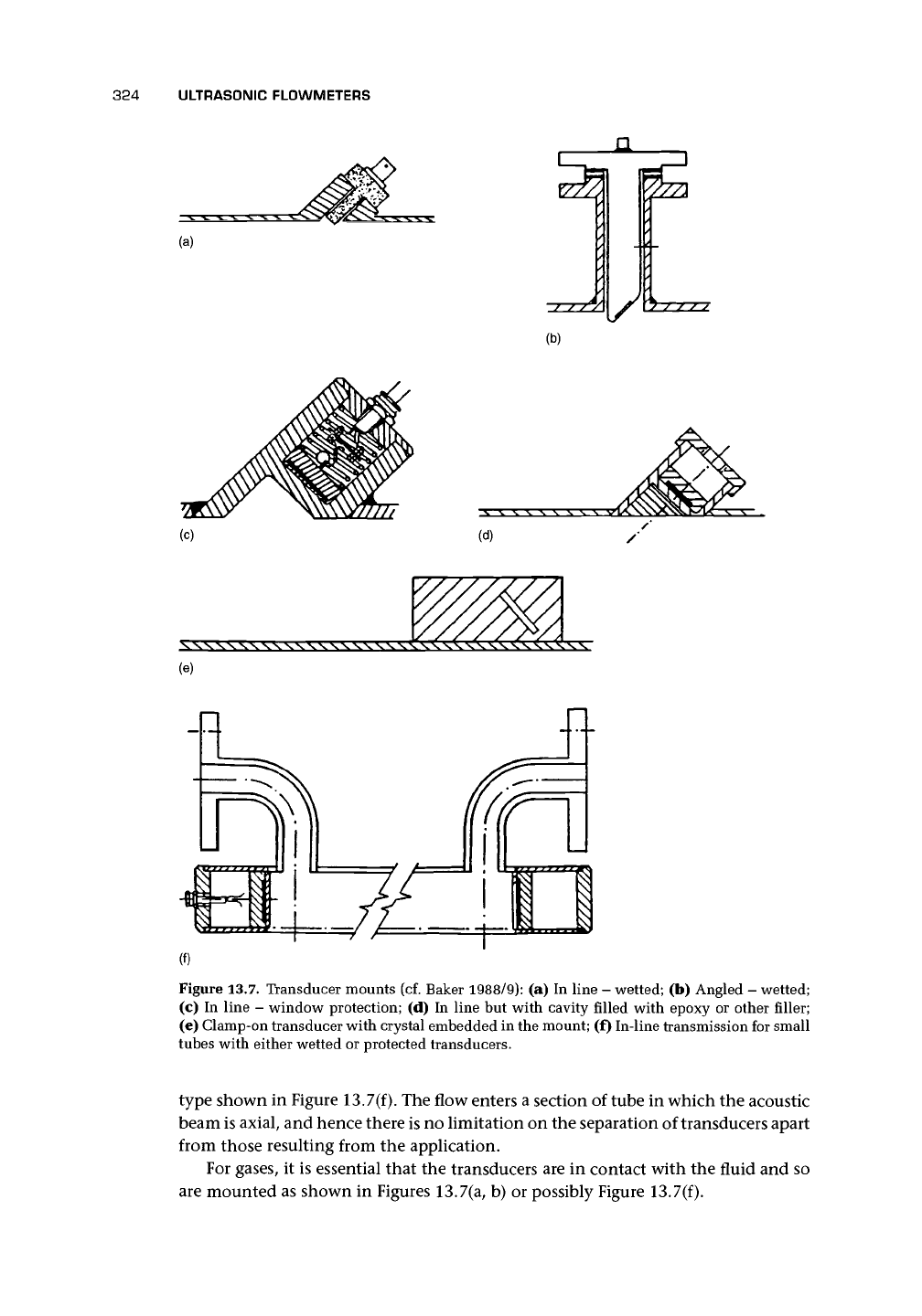
Figure 13.7 shows some typical mounts for transducers. Figure 13.7(a) shows a
wetted transducer in an angled mounting block. The crystal emits a pencil of sound
through perpendicular interfaces, and it is not therefore refracted. Figure 13.7(b)
shows an alternative arrangement with mounts perpendicular to the tube and trans-
ducer with an angled end in which the crystal is mounted. If the liquid is aggressive
or particle laden, some form of window may be required. In this case, the transducer
may be mounted as shown in Figure 13.7(c), where a metal window is used but
where all interfaces remain perpendicular to the beam. The cavity is a source of flow
disturbance and solid deposit. Both may cause signal failure or flow measurement
errors.
Figure 13.7(d) has the cavity smoothed off with a filler of some sort such as
an epoxy. Ideally, this filler should have an acoustic refractive index similar to the
liquid, thus keeping refraction to a very low value, and the bending of the acoustic
ray on crossing the interface will be small. However, changes of fluid or tempera-
ture may introduce errors. An important advantage of the mounts shown in Figures
13.7(a, b) is that alternative transmission around the tube wall and outside the fluid
is reduced, and in practice the transducer mount can be made to absorb it. With
the mounting systems in Figures 13.7(c, d), the signal processing must discriminate
between the fluid-borne signal and the spurious signals around the wall of the tube.
Sanderson and Hemp (1981) gave some details of ways to increase the bandwidth of
the piezoelectric plate.
Figure 13.7(e) shows a clamp-on system in which the transducer mount
is
entirely
external to the tube and may be mounted on existing tube. Here the problems of
the type found in the mounts shown in Figures 13.7(c, d) are greatly increased.
For very small pipe sizes, the limitations of pipe diameter and consequent short
pulse times can be overcome by a flow tube and transducer mounting system of the
324 ULTRASONIC FLOWMETERS
1/
(b)
(d)
(e)
Figure 13.7. Transducer mounts (cf. Baker 1988/9): (a) In line - wetted; (b) Angled - wetted;
(c) In line - window protection; (d) In line but with cavity filled with epoxy or other filler;
(e) Clamp-on transducer with crystal embedded in the mount; (f) In-line transmission for small
tubes with either wetted or protected transducers.
type shown in Figure 13.7(f). The flow enters a section of tube in which the acoustic
beam is axial, and hence there is no limitation on the separation of transducers apart
from those resulting from the application.
For gases, it is essential that the transducers are in contact with the fluid and so
are mounted as shown in Figures 13.7(a, b) or possibly Figure 13.7(f).
13.5 SIGNAL PROCESSING AND TRANSMISSION 325
To overcome the impedance mismatch, a low impedance transducer was re-
ported (Collings et al. 1993). When used in a meter, it allowed natural gas flows
of 0.013-8 m
3
/h with a temperature range of —13 to 47°C and is claimed to have
significant advantages over current domestic meters.
It should also be remembered that for high pressure service the transducers must
be flanged to the correct line pressure (rather than screwed). Transducers that project
into the tube may avoid attenuation and other problems due to air collection within
the pockets. To reduce turbulence caused by the transducer cavities on a 20-mm-ID
ultrasonic flowmeter for gas, nets have been placed to create a wall that transmitted
the ultrasound (Hakansson and Delsing 1992).
Lynnworth (1988) suggested the use of new types of wetted and clamp-on buffer
rods to allow for extreme temperature (e.g., ±200°C) such as might occur in wetted
use in cryogenics or in the flow of quench oil in a carbon steel pipe at 260°C.
13.4 SIZE RANGES AND LIMITATIONS
Single- and twin-path designs may be available for liquids in 80-2,000 mm diameter
or greater, although very large sizes may be retrofit applications. The arrangement
for small tubes is likely to be for 10-80 mm.
When retrofitting, there is always a tolerance on the pipe dimensions, both di-
ameter and wall thickness, which will affect the deduction of mean flow from ul-
trasound path velocity, and the measurement needs to take account of the actual
separation of transducers (Scott 1984). For instance, in a carbon steel pipe with a
100-1,000 mm diameter, the tolerance may be
±1%
on diameter and ±10% on wall
thicknesses of 3-5 mm. In addition, erosion, corrosion, and painting of the pipe
makes it improbable that the error can be reduced below 0.5%. Manufacturers may
offer retrofit for one, two, or four paths, which with precise internal measurement
should be capable of high accuracy.
13.5 SIGNAL PROCESSING AND TRANSMISSION
As indicated earlier, the measurement system essentially requires the ability to mea-
sure very small time periods, or periods to very high precision. This increment could
be of order 10~
9
(a nanosecond), which Sanderson and Hemp (1981) pointed out
was comparable with the (then) propagation delays and rise times of the fastest
commercially available logic. Clearly the technology in this area is moving rapidly,
and the problems encountered in small time measurement, phase comparison, or
sing-around are finding new solutions.
Tables 13.1 and 13.2 have identified the design requirements for the signal pro-
cessing, namely,
• for transit-time meters to measure timed differences to better than 10~
9
s (one
nanosecond) and
• for sing-around meters to measure frequency differences to better than, say,
0.03 Hz for 1% discrimination in a 300-mm tube with V = 1 m/s.
326 ULTRASONIC FLOWMETERS
To achieve this, various clock circuits have been used. In an early commercial
meter, a ramped voltage system provided a time measure. In addition, there are
problems in ensuring that the zero-pass, or whatever part of the wave is used, is
consistent between transmitters and receivers. Szebeszcyk (1994) discussed some
aspects of the design of the ultrasonic flowmeter and transducers, use of first zero
crossing of the signal, optimum thickness of matching layers, etc.
Vaterlaus (1995) described a time measurement system with two counters. One
counter N
t
was clocked during the measuring period by a stable quartz oscillator with
a frequency f
—
64 MHz, whereas the other counted the number of samples N
n
. A
start pulse initiated the measurement by activating the two counters and triggering
the ultrasonic pulse emission. During the measurement period r = 30 ms, every
pulse received caused a new pulse to be emitted. The two counts N
t
and N
n
were
used to calculate the propagation time from
N
t
/N
n
.
It appeared that x was obtained precisely from N
t
/f; hence, provided x ended
after a complete value of N
n
, it was possible to obtain the transit time as
N
t
/(N
n
f)
and a resolution of 60 ps in 116 /xs was claimed.
Advantages claimed were:
• Velocity resolution was to 0.8 mm/s.
• Precision depended on the stability of the oscillator.
• Jitter in digital logic was averaged.
Another solution to the timing problem (Pavlovic et al. 1997) appeared to use
a. a transmitted pulse in two halves, the first at one amplitude and the second at
twice the amplitude, presumably allowing more precise timing edges;
b.
the downstream and upstream times were then given by
t&
= N
d
T+ Ar
d
ta = N
U
T + Ar
u
where N
d
and N
u
were the whole number of counter periods of a 2.2-MHz square
wave train obtained from a 17.7-MHz oscillator through a divider by 8 and were
obtained by standard counter methods;
c. Ard and Ar
u
were measured through the phase difference between transmission
and received signals, and a two-stage measurement system using a coarse and
fine approach. An integrator was used to obtain Aid and Ar
u
.
The effects of error due to temperature on pipe diameter, recesses, delays in
electronics, and transducers were also addressed.
Because such short times are being measured, system designs need to address de-
lays in the cables, transducers, and converter (Scott 1984). Time delays of microsec-
onds could lead to errors if the head is calibrated on water for use on oil (±1.5%), or
if the temperature of the water changes by 10°C (±0.1%). Further delays are caused
in the window, or in the transmission through the wall, ranging from about 3 /is to
about 15 /xs. These delays will also be dependent on the choice of materials.
Hemp (1988, 1998) has proposed a reciprocity approach to the elimination of
zero instability. This requires that the transducers are driven, say, by a voltage pulse,