Baker R.C. Flow Measurement Handbook: Industrial Designs, Operating Principles, Performance, and Applications
Подождите немного. Документ загружается.

12.A.3 DEVELOPMENT OF THE WEIGHT VECTOR THEORY 307
relating to flow-induced signal will have the same phase as the applied field, and
the electric field derived from Equation (12.A.3) will have a
TT/2
phase shift and may
be eliminated by suitable electronic design. Additionally, the effect of this spurious
field may be reduced by improving the symmetry of the flowmeter.
12.A.2 ELECTRIC POTENTIAL THEORY
It may be shown (Baker 1968) that the solution of Equation (12.A. 7) for a circular
pipe with axisymmetric flow profile is given by
=
l
f
^ Jo
where r is the radial coordinate, V{r) is the axisymmetric flow profile, 6 is the
azimuthal coordinate, and B
e
(r,6) is the azimuthal component of magnetic field,
which varies with r and 0 and is constant with axial position z. p is a dummy vari-
able,
and a is the pipe radius.
The potential difference between diametrically opposed electrodes AL/
EE
is then
given by
V(Vra)B
d
(r,O)dr
For a uniform magnetic field B, this becomes
=
—
f
a
a
Jo
=
BDV
m
(12.A.12)
where D is the pipe diameter, and V^ is the mean velocity. This equation resulted
in the high expectations for the device that offered true bulk flow measurement.
However, the assumptions - uniform field and axisymmetric flow profile - were too
constraining in practice.
12.A.3 DEVELOPMENT OF THE WEIGHT VECTOR THEORY
Shercliff showed that the response to a point-electrode uniform-field electromag-
netic flowmeter, when subjected to an arbitrary rectilinear flow profile, could be
represented by a weighting function W given by
a
4
+a
2
r
2
cos 26
W=
a
4
+ 2a
2
r
2
cos 20 + r
4
where 0 is zero in the direction of the magnetic flux. This is the function shown in
Figure 12.4(a).
Bevir (1970) developed the powerful concept of the weight vector W. Bevir intro-
duced the concept of the virtual current
j
v
,
which is related to a potential function
I/vby
j
v
= -aVl/y (12.A.13)
308 ELECTROMAGNETIC FLOWMETERS
and is the current density that would exist in the flow tube in the absence of magnetic
field and flow if unit current entered by one electrode and left by the other.
He showed that (cf. Baker 1982 for a simplified derivation)
Al/
EE
= f f L
u
V-Bxjv^T (12.A.14)
LL
II /Flowtube '
v
'
J J
^ volume
where the integration is taken over the whole volume of the flowmeter tube. Bevir
introduced W as
W =
Bxj
v
(12.A.15)
and hence
volume
Bevir then showed that the necessary and sufficient condition for an ideal
flowmeter, one which measured the mean flow regardless of flow profile, was
VxW = 0 (12.A.17)
An important point to note is that Equations (12.A.16) and (12.A.17) possess
a generality beyond electromagnetic flow measurement. Bevir (1970) proposed a
rectangular section flowmeter that satisfied Equation (12.A.17), and he carried out
extreme tests to demonstrate its performance. Using noncontacting electrodes and a
special magnetic field distribution, Hemp (with Al-Khazraji 1980 and with Sanderson
1981) has designed a flowmeter, which in theory should be virtually insensitive to
flow profile effects.
12.A.4 RECTILINEAR WEIGHT FUNCTION
However, most designs have assumed a rectilinear flow and have used an appropriate
weight function W
W
f
(r,0)=
/
W
z
dz
(12.A.18)
J—oo
where W
z
is the axial component of W. This results in
AL/
EE
=
fX
lowtube
rM(r,0)W'(r,0)d0dr (12.A.19)
** **
cross-section
This is essentially Shercliff s (1962) idea, which resulted in the well-known dis-
tribution for a uniform magnetic field [Figure 12.4(a)].
Many weight function distributions have appeared in the literature since Bevir
;
s
work, and we have noted three of these:
• For a point-electrode flowmeter with rectangular coils and circular yoke (Al-
Rabeh and Baker 1979) [Figure 12.4(b)]. This type of flowmeter is of interest
in that it approximates to some industrial flowmeters.
12.A.4 RECTILINEAR WEIGHT FUNCTION 309
• For a point-electrode flowmeter with diamond coils [Figure 12.4(c)] and circular
yoke, which approximates to one introduced in the 1960s and claimed to have
a reduced sensitivity to flow profile distortion.
• For a large electrode flowmeter with rectangular coils and yoke (Al-Khazraji and
Baker 1979), shown diagrammatically in Figure
12.13,
for which the weight func-
tion is reproduced in Figure 12.4(d).
The improvement obtained in the uniformity of W by use of diamond coils
instead of rectangular coils is very noticeable, and there is even more improvement
by using large electrodes. However, a major disadvantage of these is the change in
sensitivity resulting from electrode fouling (Al-Khazraji and Baker 1979).
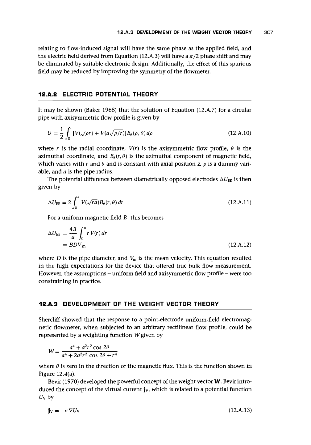
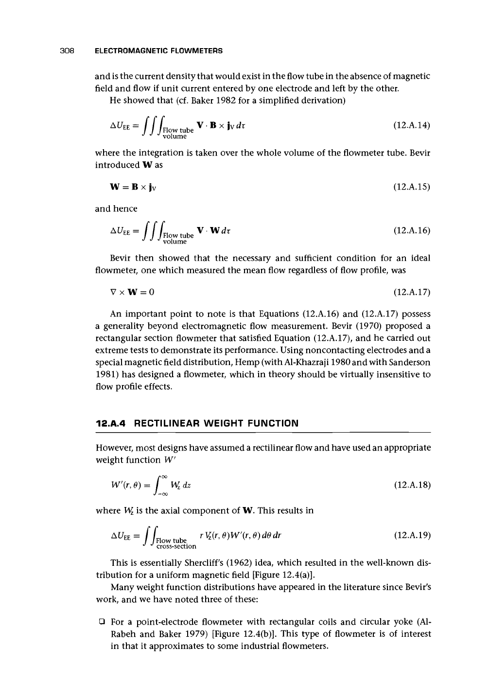
Hemp (1975) attempted to minimize the variation of weight function with the
copper strip pattern in Figure 12.A.l(a). Figure 12.A.l(b) shows the resulting weight
function distribution, which should be compared with those in Figure 12.4. The
axisymmetric weight function was approximately constant for about 87% of the
pipe falling to zero at the wall (Figure 12.A.2).
(a)
-0-94
n
O;843
1-87
124
936
Figure 12.A.1. Hemp's (1975) improved
magnetic field design: (a) Copper strip
pattern associated with the improved
magnetic field. The number associated
with each line is the value of the mag-
netic field potential function, and the ar-
rows,
which are equal in size in each
strip,
show the direction of the current;
(b) Weight function diagram for the im-
proved magnetic field (refer to the origi-
nal paper for further details; reproduced
with permission from the author and IoP
publishing).
310
ELECTROMAGNETIC FLOWMETERS
w"
1.2
r
1.1
1.0
0.9
0.8
0.7
0.6
0.5
SHERCLIFF
LARGE ELECTRODE
DIAMOND COILS
HEMP (1975)
RECTANGULAR
COILS
r/a
1.0
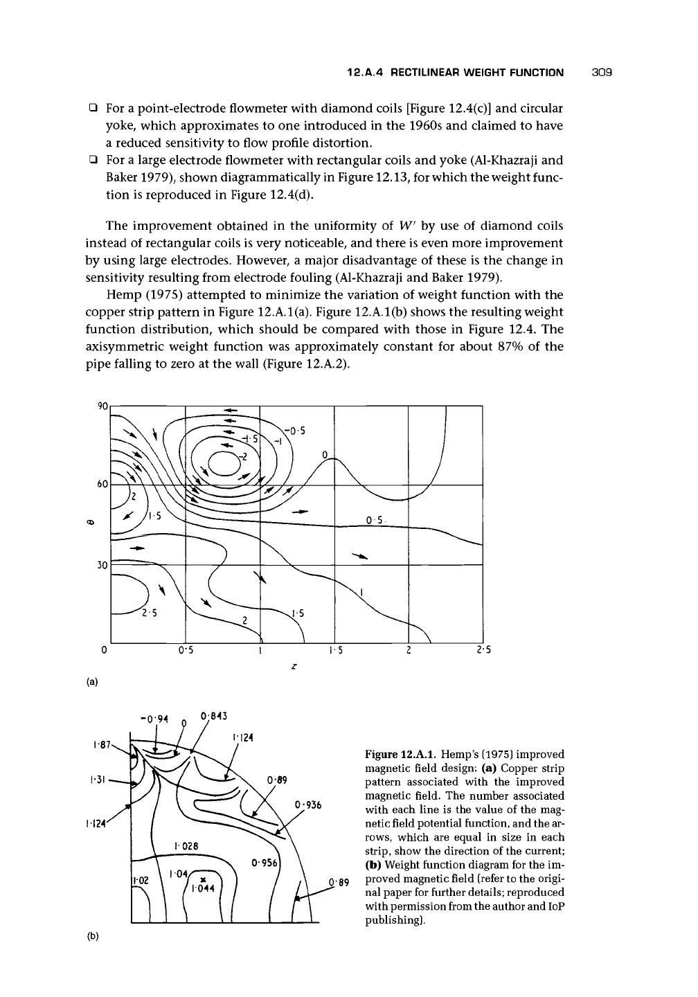
Figure 12.A.2. Axisymmetric weight functions based
on
Figures 12.4
and
12.A.1.
12.A.5 AXISYMMETRIC WEIGHT FUNCTION
In concluding this section on the theory,
it
is useful to refer briefly to the axisym-
metric weight function. This is given by
W"{r)=—\
/
W
z
dzd0
Z7T
Jo J_
oo
(12.A.20)
Its value
for a
uniform field
is
constant and unity. However,
for
most prac-
tical fields,
it
falls
in
value
at
the outside
of
the tube. This trend
is
illustrated
in Figure 12.A.2, which gives plots
for
Shercliffs uniform field weight function
[Figure 12.4(a)] and by interpolation for the others
in
Figure 12.4. The signal
is
given by
AU
E
,
=
2TT
f
rW"<
Jo
(r)V
z
(r)dr (12.A.21)
Thus as flow profiles change with increasing Reynolds number from being more
peaked in the center of the pipe to more uniform across the pipe, the signal will fall
below direct proportionality.
12.A.6 PERFORMANCE PREDICTION
Apart from the design problem, but related to it, has been the accuracy with which
performance could be predicted from theory. This is the problem of dry calibration.
Equation (12.A. 12) suggested a very simple prediction for a uniform field flowmeter.
However, the precision
of
such prediction has always been uncertain. Bevir
et
al.
(1981) have described a very elegant piece of work in which magnetic field measure-
ments around the tube wall were used to compute the weight function, and very
good agreement was obtained between prediction based on pipe flow profiles and
12.A.7 FURTHER EXTENSIONS TO THE THEORY 311
actual meter response. They concluded that sensitivities would be predicted for most
flowmeters by their procedures with an error of not more than 0.5%.
Al-Rabeh and Baker (1986) have attempted to predict the performance of a
flowmeter from its magnet design. However, although good qualitative agreement
on distribution of field was obtained, they found a discrepancy between predicted
and actual field size. Thus with care, high accuracy prediction of flow signal may be
achieved from actual magnetic field distribution.
Others have developed this approach by measuring and/or predicting the field
at the pipe wall and using this to calculate the weight function.
12.A.7 FURTHER EXTENSIONS TO THE THEORY
The reader who is interested in various extensions of the theory is referred to the
following papers by Hemp and co-workers.
Hemp and Wyatt (1981) explored the use of a "worst flow" to compare electro-
magnetic flowmeter performance.
Hemp and Versteeg (1986) developed the analysis of the flowmeter performance
based on the magnetic field on the flowmeter surface. This approach would
allow 'dry calibration' of a meter based on magnetic field measurements on a
tube next to the inner surface.
Krafft et
al.
(1996) discussed the use of the transformer effect signal due to bubbles
to obtain both bubble velocity and velocity of the continuous phase of
a
bubbly
flow.
Hemp (1991) developed the theory of eddy currents in electromagnetic flowme-
ters and suggested a means of self-calibration. Hemp also (1994c) looked at
errors in potential measurement due to nonuniform contact impedance at the
electrodes.
CHAPTER
13
Ultrasonic Flowmeters
13.1 INTRODUCTION
The first proposal for the use of ultrasound for flow measurement, according to
Thompson (1978), seems to have been in a German patent of 1928. It was not until
after 1945 that the idea became more widely proposed. But not until the devel-
opment of piezoelectric transducers in the past 40 years or so have ultrasonic ap-
plications become really attractive. Fischbacker (1959) provided an early review of
ultrasonic flowmeters in which, essentially, the transit-time, sing-around, and beam
deflection methods were mentioned. He also referred to phase-difference measure-
ment, means of obtaining sound speed from time measurement and impedance, and
how to obtain density. He saw the advantages of off-axis paths.
Sanderson and Hemp's (1981) review is still a useful source of information on
the subject. The ultrasonic flowmeter's attraction as a flow measurement device is
its linearity, lack of obstruction to flow, and, in contrast to the magnetic flowmeter,
its ability to measure the flow of gases.
In this chapter, we shall consider three main types of ultrasonic flowmeter, and
it is important to understand the strengths and weaknesses of each and that they
are very different in performance and application.
The transit-time flowmeter, or time-of-flight flowmeter, is the most accurate of
the family and
is
available as a spool piece meter for liquids and gases or
as
a clamp-on
design for liquids only. It can also be retrofitted into
a
pipe.
Measurement uncertainty
will be from a fraction of a percent to about 5%.
A
transducer in direct contact with
the fluid is said to be wetted, as compared to one that is fixed to the outside of the
pipe or has a protective layer between it and the fluid. Transducers for gases must be
in contact with the gas (i.e., wetted, a rather inappropriate word for this context!).
The doppler meter is a very different device, and it may be unfair to call it a
flowmeter. Its performance is very sensitive to installation, and it has been oversold
to such an extent that many people assume that, when an ultrasonic flowmeter
is mentioned, it is one of these. Measurement uncertainty is unlikely to be better
than about ±2%, and at worst it is indeterminate. Having said this, it has a very
important niche in some liquid flow applications where there is an adequate second
component to provide reflection of the beam.
The cross-correlation flowmeter should be capable of reasonable precision (be-
tween the preceding two devices), requires a disturbed liquid or multiphase flow to
operate satisfactorily, is likely to be much more expensive than either of the other
types,
and is mainly of interest for measurement in multiphase flows.
312
13.1 INTRODUCTION 313
It is not unusual for other meters that have ultrasonic sensing to be referred to
as ultrasonic meters. One such meter is the vortex-shedding meter with ultrasonic
sensing.
Beyond these, there is the possibility of using the deflection of the beam to mea-
sure flow rate, but to my knowledge this has not been done commercially. There is
also the possibility of measuring density and so turning the meter into a mass meter.
It is important not to confuse the transit-time meter with the doppler meter and
to appreciate that the transit-time ultrasonic meter is a far more accurate instru-
ment than the doppler meter and should be considered seriously in a wide range of
applications, especially involving nonconducting liquids or gases.
We shall treat each type of ultrasonic flowmeter in turn. All are based on the fact
that ultrasound is made up of acoustic waves at frequencies above the audible range.
As a form of sound, ultrasound waves travel with the speed of sound relative to the
medium and consist of pressure perturbations in gases and liquids. In solids, the con-
necting wave can also move as a shear
wave,
due to the elasticity of the solid in shear.
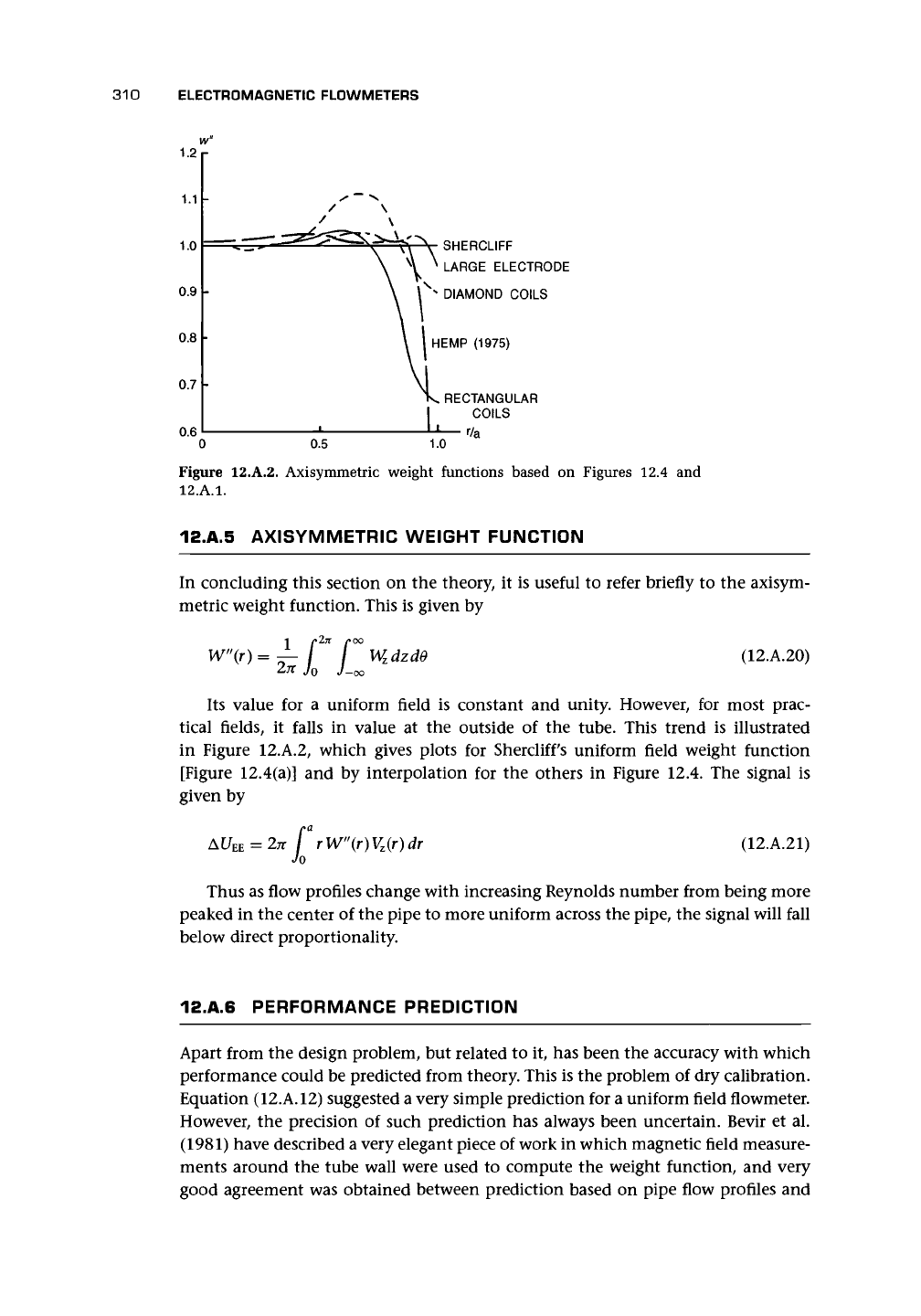
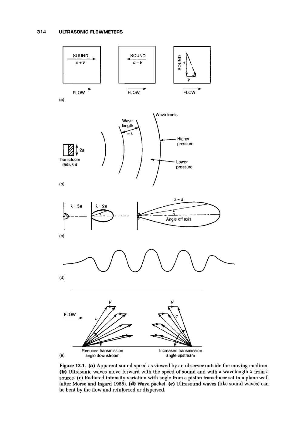
In Figure 13.1
(a),
we note that the ultrasound is carried by the fluid, so that its
speed is the sum or difference of its own speed c and that of the fluid V. This is the
basis of the transit-time meter, which uses the difference in time of transit in an
upstream and a downstream direction. If the sound is crossing the flow, then the
apparent speed is obtained from the hypotenuse of the triangle in the third example
of Figure 13.1
(a).
In flowmeters, the continuous wave [Figure 13.1(b)] is sometimes used. The di-
agram shows the main features of the wave pattern, with the wave length and the
higher and lower pressure regions. The frequency f is related to the sound speed c
and wavelength k by f = c/k. The intensity of the transmission varies according to
the angle off the perpendicular axis through the transducer. Three patterns are shown
in Figure 13.1(c) for three different ratios of the transducer radius a to the wave-
length. The higher the frequency and the shorter the wavelength, the more pencil-
like the transmitted beam. A narrow beam is preferable to a wide one because it is
less likely to cause spurious reflections, and its path will be better defined. For a speed
of sound in water of 1414 m/s, a frequency of 400 kHz will result in a wavelength
of about 3.5 mm, whereas
1
MHz will result in 1.4 mm. For a speed of sound in air of
343 m/s, a frequency of 40 kHz will result in a wavelength of about 8 mm, whereas
100 kHz will result in about 3.4 mm. Thus for air with k = 2a, the diameter of the
piezoelectric crystal to obtain the middle distribution in Figure 13.1(c) at 40 kHz will
be about 8 mm, whereas the crystal diameters for water are likely to be such that
k < a and result in a narrow intense beam.
More commonly the ultrasound is sent in a small burst of waves. Figure 13.1(d)
shows an idealized diagram of a short burst of waves transmitted across the flow.
However, the sweeping effect [Figure 13.1(e)] will mean that the direction of the
beam will be a compromise between high and low flow rates to ensure that it arrives
at the receiving transducer. Another feature of the bending of the beam is that there
is a tendency for downstream sound to be reinforced and for upstream sound to be
diffused and weakened (cf. Baker 1996, page 2).
When ultrasound crosses an interface between two different fluids or between
a fluid and a solid, there is both transmission and reflection at the interface. The
transmission will be greater if the density times wave speed of the two materials
314
ULTRASONIC FLOWMETERS
SOUND
c + V
SOUND
c-y
a
Z> C
K
V
FLOW
FLOW
FLOW
(a)
V
Wave fronts
[It
2a
Transducer
radius a
(b)
- Higher
pressure
Lower
pressure
(c)
FLOW
(e)
Reduced transmission
angle downstream
Increased transmission
angle upstream
Figure 13.1. (a) Apparent sound speed as viewed by an observer outside the moving medium.
(b) Ultrasonic waves move forward with the speed of sound and with a wavelength
X
from a
source, (c) Radiated intensity variation with angle from a piston transducer set in a plane wall
(after Morse and Ingard 1968). (d) Wave packet, (e) Ultrasound waves (like sound waves) can
be bent by the flow and reinforced or dispersed.
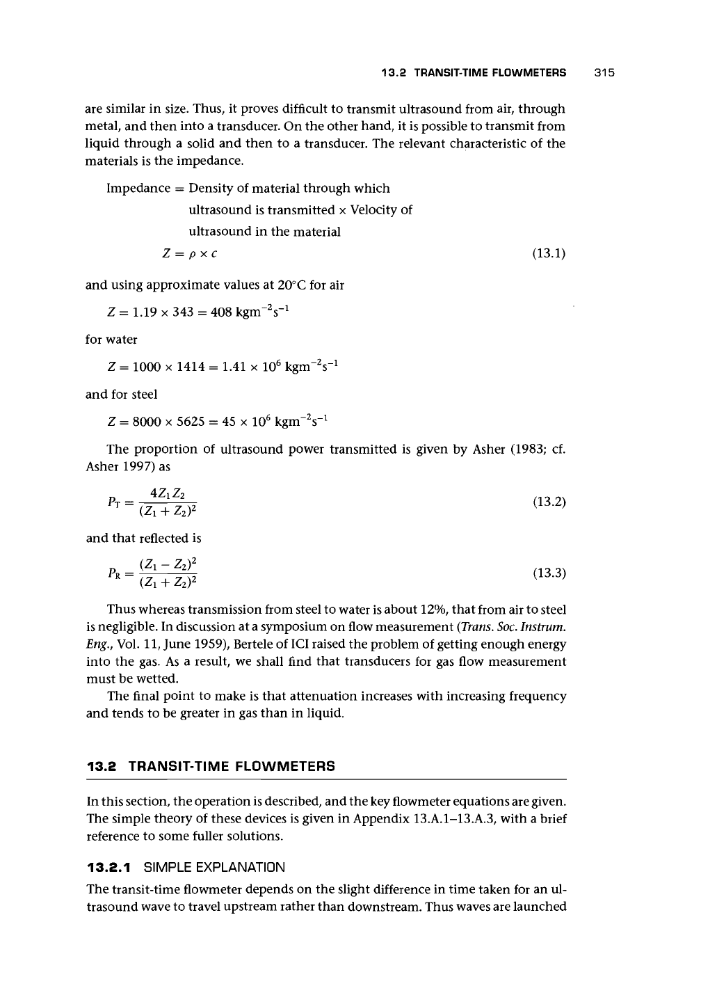
13.2 TRANSIT-TIME FLOWMETERS 315
are similar in size. Thus, it proves difficult to transmit ultrasound from air, through
metal, and then into a transducer. On the other hand, it is possible to transmit from
liquid through a solid and then to a transducer. The relevant characteristic of the
materials is the impedance.
Impedance = Density of material through which
ultrasound is transmitted x Velocity of
ultrasound in the material
Z
=
pxc
(13.1)
and using approximate values at 20° C for air
Z = 1.19 x 343 = 408 kgnrV
1
for water
Z = 1000 x 1414 = 1.41 x 10
6
kgnrV
1
and for steel
Z = 8000 x 5625 = 45 x 10
6
kgm~V
1
The proportion of ultrasound power transmitted is given by Asher
(1983;
cf.
Asher 1997) as
2
(13.2)
(Zi + z
2
y
and that reflected is
Thus whereas transmission from steel to water is about 12%, that from air to steel
is negligible. In discussion at a symposium on flow measurement
(Trans.
Soc.
Instrum.
Eng.,
Vol.
11,
June 1959), Bertele of ICI raised the problem of getting enough energy
into the gas. As a result, we shall find that transducers for gas flow measurement
must be wetted.
The final point to make is that attenuation increases with increasing frequency
and tends to be greater in gas than in liquid.
13.2 TRANSIT-TIME FLOWMETERS
In this section, the operation is described, and the key flowmeter equations are given.
The simple theory of these devices is given in Appendix 13.A.1-13.A.3, with a brief
reference to some fuller solutions.
13.2.1 SIMPLE EXPLANATION
The transit-time flowmeter depends on the slight difference in time taken for an ul-
trasound wave to travel upstream rather than downstream. Thus waves are launched
316
ULTRASONIC FLOWMETERS
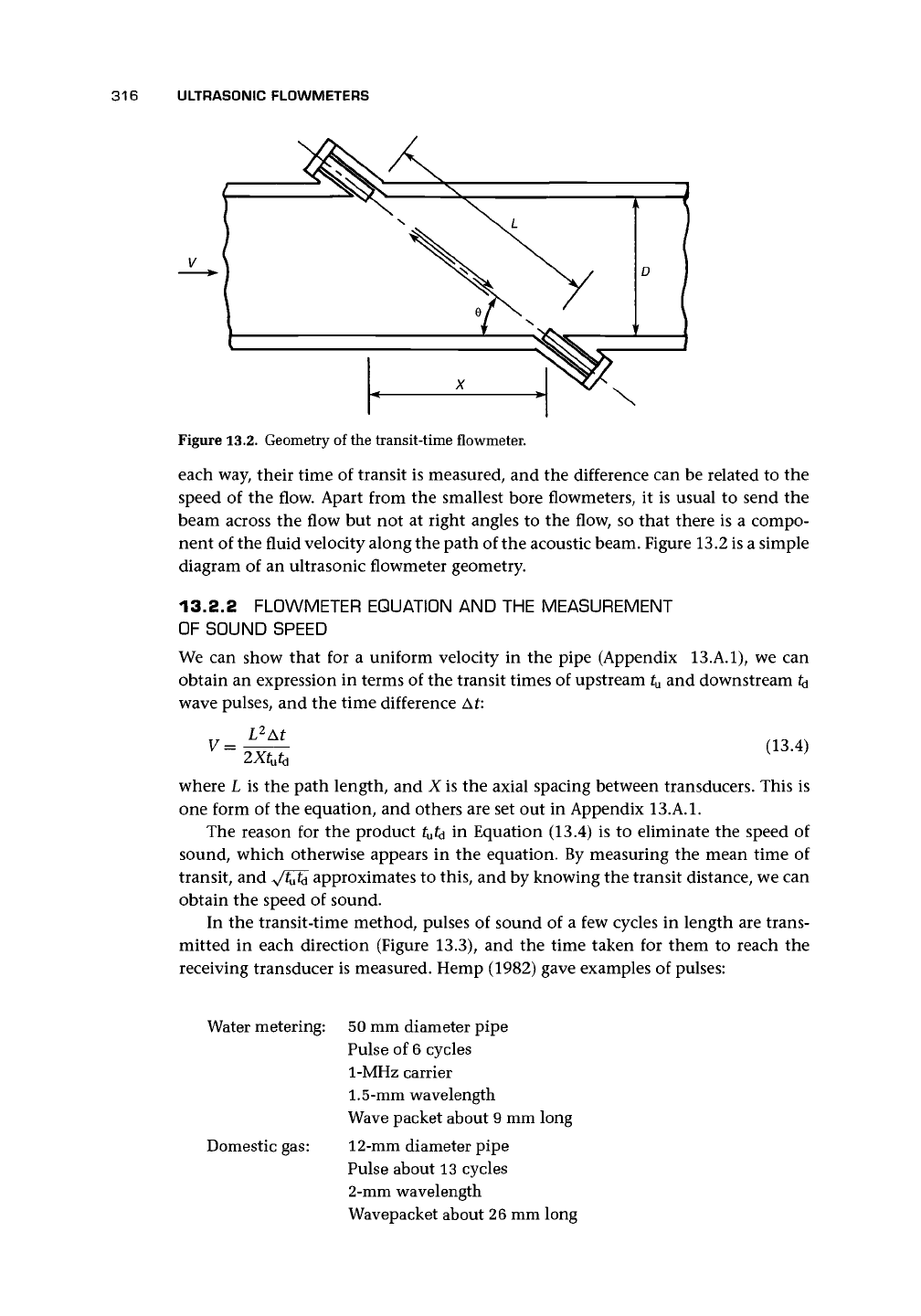
Figure 13.2. Geometry of the transit-time flowmeter.
each way, their time of transit is measured, and the difference can be related to the
speed of the flow. Apart from the smallest bore flowmeters, it is usual to send the
beam across the flow but not at right angles to the flow, so that there is a compo-
nent of the fluid velocity along the path of the acoustic beam. Figure 13.2 is a simple
diagram of an ultrasonic flowmeter geometry.
13.2.2 FLOWMETER EQUATION AND THE MEASUREMENT
OF SOUND SPEED
We can show that for a uniform velocity in the pipe (Appendix 13.A.1), we can
obtain an expression in terms of the transit times of upstream t
u
and downstream ^
wave pulses, and the time difference At:
L
2
At
V =
(13.4)
where L is the path length, and X is the axial spacing between transducers. This is
one form of the equation, and others are set out in Appendix
13.A.1.
The reason for the product
t
u
td
in Equation (13.4) is to eliminate the speed of
sound, which otherwise appears in the equation. By measuring the mean time of
transit, and VMi approximates to this, and by knowing the transit distance, we can
obtain the speed of sound.
In the transit-time method, pulses of sound of a few cycles in length are trans-
mitted in each direction (Figure 13.3), and the time taken for them to reach the
receiving transducer is measured. Hemp (1982) gave examples of pulses:
Water metering:
Domestic gas:
50 mm diameter pipe
Pulse of
6
cycles
1-MHz carrier
1.5-mm
wavelength
Wave packet about 9 mm long
12-mm diameter pipe
Pulse about 13 cycles
2-mm wavelength
Wavepacket about 26 mm long