Baker R.C. Flow Measurement Handbook: Industrial Designs, Operating Principles, Performance, and Applications
Подождите немного. Документ загружается.

14.5 CHAPTER CONCLUSIONS 367
The Kongsberg/Shell meter uses capacitance to obtain the gas-liquid interface in
the channel, the oil-water fraction, and, by cross correlation, the slug velocity and
to estimate the individual flow rates.
The Multi-Fluid International (MFI) meter is suitable for flows with continuous
oil component. The composition is obtained with microwave and gamma radiation,
and velocity is measured using cross correlation between two dielectric sensing sec-
tions.
Okland and Berentsen (1994) described tests of the MFI, which suggested that
after optimization the MFI could achieve uncertainty on oil flow rate within 5%.
Using a combination of venturi, capacitor, and single-beam gamma densitome-
ter, Fischer (1994) showed that, provided the mixture was homogeneous, the mass
flow rates of the components of oil-water-air could be obtained within about ±25%.
Another method that has been looked at is pulsed neutron techniques (Anon.
1993).
Ekrann et al. (1988) included flow measurement as part of a capacitive system
presumably by using a correlation method.
The trend appears to be toward a meter that allows full-bore measurement of
all components, although removal of a small sample may allow a higher precision
while the technology develops.
Whitaker and Millington (1993) concluded that, from available evidence, the
then state of the art should have allowed phase flow rates to be measured to ap-
proximately 10% over reasonably wide operating envelopes. Whitaker (1993) also
appeared to conclude that 10% or so bulk measurement uncertainty was unlikely to
be bettered without new technologies and more recently (Whitaker 1996) confirmed
the ±10% of reading for four meters: Agar, Fluenta, Framo, and MFI.
See also North Sea Flow Measurement Workshops 1992, 1993, and 1994 for fur-
ther papers on multiphase flow meters and mixers.
14.5 CHAPTER CONCLUSIONS
This chapter has been concerned with a wide range of mass flow measurement
that falls outside the meters discussed in Chapters 15-17. Apart from the hydraulic
Wheatstone bridge method that has had a particular market niche, the other multi-
meter methods are likely to be in competition with the increasingly versatile Coriolis
meter. The most promising multimeter development is likely to include ultrasonics.
It is in the area of multiphase flows that the major developments are likely to oc-
cur, backed by the considerable cost advantages that result from subsea multiphase
flow measurement. These are likely to have improved component ratio measure-
ment and clever data handling to obtain the most information. We shall, therefore,
concentrate on these, always remembering that other areas of industry beyond the
oil industry will benefit from such developments.
14.5.1 WHAT TO MEASURE IF THE FLOW IS MIXED
It would be satisfactory to have a flowmeter that could interpret all the variables that
occur in a multicomponent flow. Such a device might identify the position on a flow
pattern chart for well-documented fluids. It could also deduce the mass flow of each
component. The state of the art has not reached that point yet, and it is likely to be
368 MASS FLOW MEASUREMENT USING MULTIPLE SENSORS
several years before it does. It is therefore important to consider what variable we
are seeking in the measurements that are being made now. The most useful measure
is clearly mass flow of the separate components. But the sophistication needed to
achieve this for gases and liquids, without errors due to water, sand, and wax, is
high, and most methods will need to compromise.
Beg and Toral (1993) reported on the use of pattern recognition techniques to
obtain superficial gas-liquid flow rates. They reckoned that the techniques could be
extended to oil-water-gas flows by using pressure sensing and an orifice plate with
capacitance and gamma ray. They introduced a new hydrodynamic system for scal-
ing pipe diameter and fluid properties and used neural network pattern recognition
techniques (cf. Toral et al.'s 1990 computer package).
The use of mixing to create an almost homogeneous flow also has drawbacks.
The flow downstream of a mixer is extremely disturbed, and such a position would
certainly not be recommended for precise conventional flow measurement. In many
cases,
the flow also starts to separate as soon as it is mixed. The flowmeter would
need to be calibrated in these flow conditions, and such a calibration would need to
take account of the effect of varying component ratios. The possibility of using the
pressure loss across the mixer was noted earlier.
14.5.2 USABLE PHYSICAL EFFECTS FOR DENSITY MEASUREMENT
Because it is unlikely that direct mass flow measurement will be suitable for multi-
phase flows, we need to consider the indirect measurements that could be combined
with a flow rate measurement. These are
• weighing elements;
• vibrating elements;
• acoustic methods (sound speed, acoustic impedance);
• electromagnetic field methods (magnetic resonance, electrical capacitance, static
charge); and
• nuclear radiations (X-ray, microwave, gamma).
It becomes apparent that, for two-component flows, some of these are unsuitable
because, for instance, bubbles and particles do not follow vibrating movements. Op-
tical (transmission problems) and thermal (heat transfer across boundaries) methods
have not been listed because they, also, are unlikely to be suitable (cf. King 1990).
However, Dykesteen et al. (1985) suggested that the measurement of resistance
and capacitance could achieve multicomponent ratio measurement. One manufac-
turer has offered a full-bore device for measuring water in oil from 0 to 80% using
capacitance methods for pipe diameters up to 300 mm and with the possibility of
a ceramic-lined device for pressures above 16 bar. Microwaves are used by another
manufacturer for the measurement of water in oil by absorption. Nucleonic mea-
surement has also been offered commercially as part of a three-phase unit for oil,
water, and gas. Frantzen and Dykesteen (1990) report a multiphase fraction meter
combining capacitance and gamma radiation, which looks very promising. Gains-
ford (1990) described meters to obtain water fraction in oil, as well as oil, water,
and gas fractions. It appears that microwave or gamma radiation were used for the
former and a combination for the latter.
14.5 CHAPTER CONCLUSIONS 369
Work in Shell laboratories (van Santen et al. 1995) also suggested that dual-
energy absorption techniques with gamma- or X-rays may offer an on-line moni-
toring method for individual fractions of oil, water, and gas in pipelines but may
be subject to errors from change in water salinity and also possibly from changes in
distribution in space and time.
14.5.3 SEPARATION
OR
MULTICOMPONENT METERING
The problems relating to the accurate measurement of multicomponent flow are
so great that separation has been the only viable route in most cases. Whether
separation of the components continues to be used will depend on the following
conditions.
a. The components are separable. This may be difficult in truly two-phase fluids
and in fluids where the finished product contains several components such as
liquid foods.
b.
The environment is conducive to separation. Subsea separation may be more
difficult than multicomponent flow metering.
c. The ultimate level of accuracy required can be achieved without separation.
d. A complete system for multicomponent flow, pumps, valves, etc., is available.
Separation of the components and subsequent measurement of each component
may offer the quickest route to an accuracy that approaches fiscal requirements, but
in the longer term competitive methods that do not separate may result from elegant
applications of more advanced physics and clever computational interpretation of
signals.
14.5.4 CALIBRATION
National Engineering Laboratory, Scotland, now has the facilities to test multiphase
flowmeters for hydrocarbon flows (cf. King 1990).
It is tempting to suggest, as for single-component calibration rigs, that the test
section of such a rig should be preceded by a long settling length to obtain fully
developed flow. However, there are good reasons why such an approach is less ap-
propriate for a multicomponent rig.
i. The settling length may be impracticably long.
ii.
The orientation of the pipe will affect the flow, and a long settling length will
prohibit other than horizontal orientations.
iii.
It is virtually certain that actual installation positions will not have fully devel-
oped flow conditions.
iv. The enormous range of flow conditions requires that the flowmeter accuracy is
not dependent on particular flow conditions.
A
more appropriate design for such a rig is likely to be a test section preceded by a
short upstream section and a manifold for component injection. By selection of the
injection manifold, flow regimes could be constructed upstream of the flowmeter.
The whole unit including manifold, upstream section, and test section would be
short enough to rotate to any orientation so that both horizontal and vertical flows
could be simulated. The outlet flow through a flexible pipe would enter a separator
370 MASS FLOW MEASUREMENT USING MULTIPLE SENSORS
before recirculation. Such a rig may also have a small enough total volume to allow
live crude to be used as one component for oil-related flows.
Other combinations of flow components for other industries may lend them-
selves to other rigs using more conventional calibration methods such as volume
and mass measurements of the total flow passed.
See also Mazzoni et al. (1994) for a description of a multiphase test facility.
14.5.5 ACCURACY
The errors in the papers reviewed on multicomponent/multiphase flows range from
±1 % for an ultrasonic correlation flowmeter in paper pulp flow, for example, to as
much as 25% for one of the offshore oil flow measurement systems. This range of
error is symptomatic of the problem for the flowmeter designer. For control and dis-
tribution, a measurement uncertainty of order ±10% may be acceptable. However,
high accuracy is required for fiscal and custody transfer applications, and here the
level that can be achieved by the designer is far from clear. Is even ±5 % achievable
in multicomponent oil flow measurement?
CHAPTER
15
Thermal Flowmeters
15.1 INTRODUCTION
There are broadly two concepts of thermal flowmeter now available for gas mass
flow measurement, one of which is also applicable to liquids. I shall follow the use-
ful terminology in ISO committee draft (ISO/CD 14511:1998) for the two types. The
first is the capillary thermal mass flowmeter (CTMF), which has broad applications
in the control of low flows of clean gases, but which can also be used with a by-
pass containing a laminar element to allow higher flow rates to be measured. The
arrangement of heaters and coils between the various manufacturers differs, but the
basic approach is the same, with heat added to the flowing stream and a temperature
imbalance being used to obtain the flow rate.
The second is the full-bore thermal mass flowmeter (ITMF), which is available
as both insertion probe and in-line type. It has a widely used counterpart in the
hot-wire anemometer for measurement of local flow velocity, but, as the need for a
gas mass flowmeter has become evident, it has been developed as a robust insertion
probe for industrial usage and then as the sensing element in a spool piece flowmeter.
It has been produced by an increasing number of manufacturers in recent years as a
solution to the need for such a mass flowmeter.
15.2 CAPILLARY THERMAL MASS FLOWMETER - GASES
In various examples of the CTMF, the gas flows through a very small diameter tube
that has heating and temperature-measuring sensors. For larger flows, this is used
with a bypass laminar flow element in the main gas stream. In many cases, the
mass flowmeter is in one unit with the control electronics and the gas control valve.
However, in this chapter our interest is in the meter
itself.
15.2.1 DESCRIPTION OF OPERATION
In this design of thermal flowmeter, the gas flows through a very small diameter
tube,
with a sufficient length-to-diameter ratio to ensure laminar flow, and on the
outside of which there are heating and temperature-sensing windings. The heater
winding transfers heat through the wall of the tube to the gas. If there is a gas flow,
the heated gas is carried downstream. The downstream temperature sensor will then
sense a higher temperature than the upstream sensor. This differential can then be
used to deduce the mass flow. A diagram is shown in Figure 15.1
(a).
The equation
371
372
THERMAL FLOWMETERS
HEATER
(a)
(b)
TEMPERATURE^-
SENSORS
HEATERS
(c)
(d)
LAMINAR FLOW
BYPASS ELEMENT
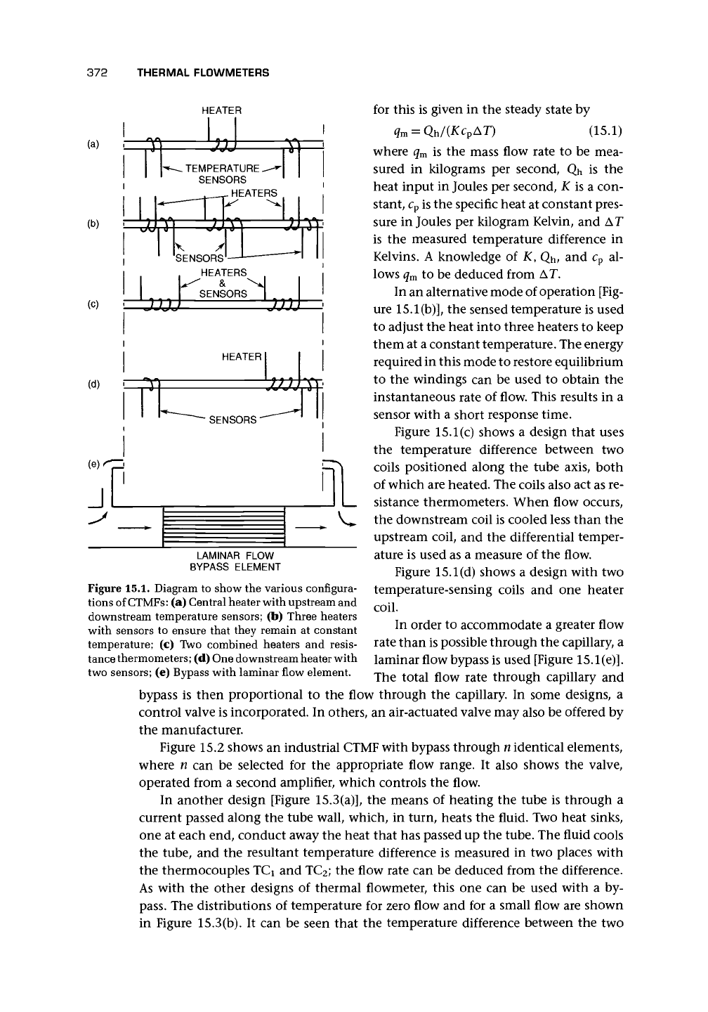
Figure 15.1. Diagram to show the various configura-
tions of CTMFs: (a) Central heater with upstream and
downstream temperature sensors; (b) Three heaters
with sensors to ensure that they remain at constant
temperature; (c) Two combined heaters and resis-
tance thermometers; (d) One downstream heater with
two sensors; (e) Bypass with laminar flow element.
for this is given in the steady state by
q
m
= Qh/(Kc
v
AT) (15.1)
where q
m
is the mass flow rate to be mea-
sured in kilograms per second, Qh is the
heat input in Joules per second, K is a con-
stant, c
p
is the specific heat at constant pres-
sure in Joules per kilogram Kelvin, and AT
is the measured temperature difference in
Kelvins. A knowledge of K, Qh, and c
p
al-
lows q
m
to be deduced from AT.
In an alternative mode of operation [Fig-
ure 15.1(b)], the sensed temperature is used
to adjust the heat into three heaters to keep
them at a constant temperature. The energy
required in this mode to restore equilibrium
to the windings can be used to obtain the
instantaneous rate of flow. This results in a
sensor with a short response time.
Figure 15.1(c) shows a design that uses
the temperature difference between two
coils positioned along the tube axis, both
of which are heated. The coils also act as re-
sistance thermometers. When flow occurs,
the downstream coil is cooled less than the
upstream coil, and the differential temper-
ature is used as a measure of the flow.
Figure 15.1(d) shows a design with two
temperature-sensing coils and one heater
coil.
In order to accommodate a greater flow
rate than is possible through the capillary, a
laminar flow bypass is used [Figure 15.1(e)].
The total flow rate through capillary and
bypass is then proportional to the flow through the capillary. In some designs, a
control valve is incorporated. In others, an air-actuated valve may also be offered by
the manufacturer.
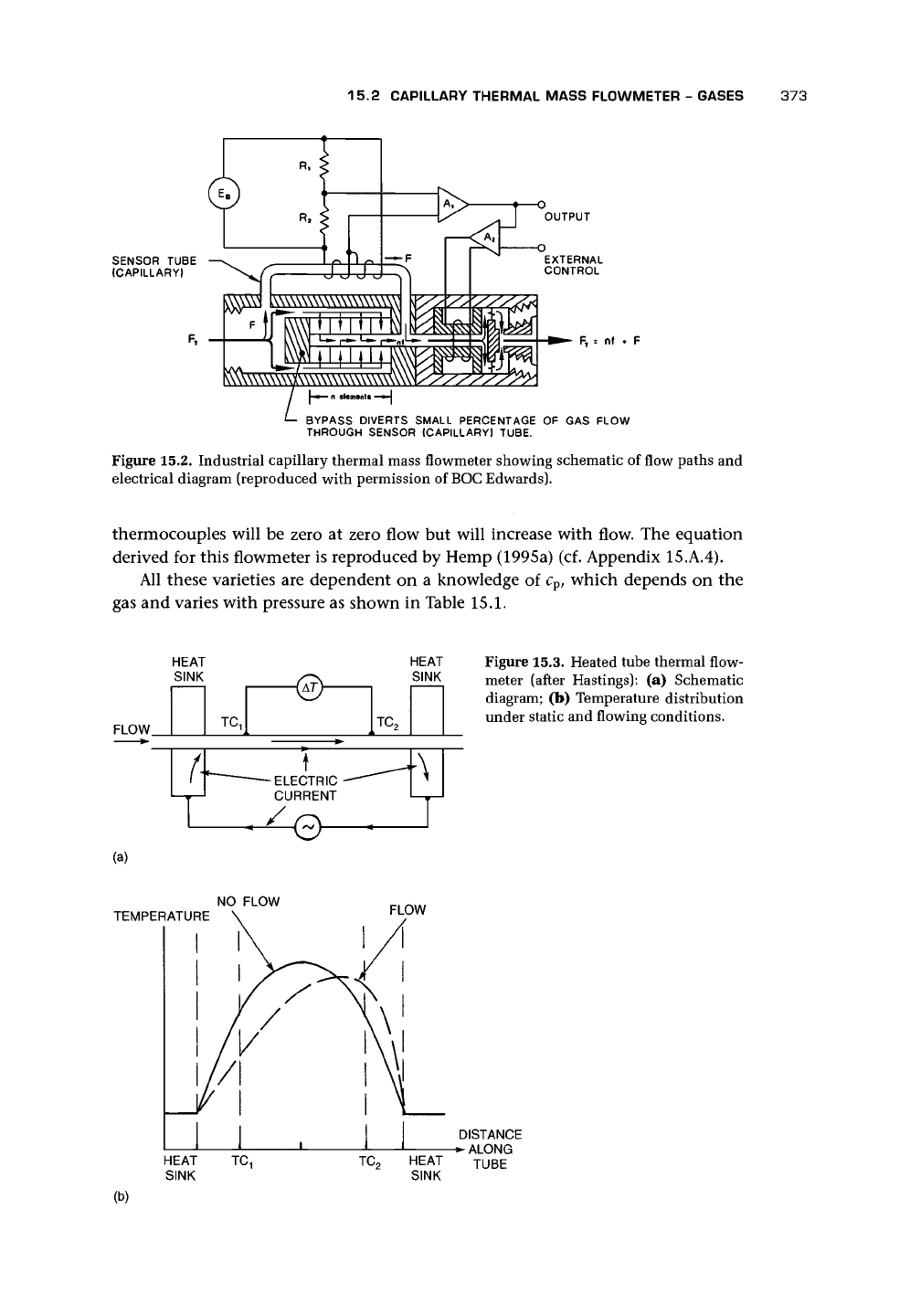
Figure 15.2 shows an industrial CTMF with bypass through n identical elements,
where n can be selected for the appropriate flow range. It also shows the valve,
operated from a second amplifier, which controls the flow.
In another design [Figure 15.3(a)], the means of heating the tube is through a
current passed along the tube wall, which, in turn, heats the fluid. Two heat sinks,
one at each end, conduct away the heat that has passed up the tube. The fluid cools
the tube, and the resultant temperature difference is measured in two places with
the thermocouples TCi and TC
2
; the flow rate can be deduced from the difference.
As with the other designs of thermal flowmeter, this one can be used with a by-
pass.
The distributions of temperature for zero flow and for a small flow are shown
in Figure 15.3(b). It can be seen that the temperature difference between the two
15.2 CAPILLARY THERMAL MASS FLOWMETER - GASES
373
SENSOR TUBE
(CAPILLARY}
R,
wwwwwwwwwww
^\\\\\\\\3(\\\\\\\\\\\\\M\v
OUTPUT
EXTERNAL
CONTROL
F
T
--
nf
L
BYPASS DIVERTS SMALL PERCENTAGE OF GAS FLOW
THROUGH SENSOR (CAPILLARY) TUBE.
Figure 15.2. Industrial capillary thermal mass flowmeter showing schematic of flow paths and
electrical diagram (reproduced with permission of
BOC
Edwards).
thermocouples will be zero at zero flow but will increase with flow. The equation
derived for this flowmeter is reproduced by Hemp (1995a) (cf. Appendix 15.A.4).
All these varieties are dependent on a knowledge of c
p
, which depends on the
gas and varies with pressure as shown in Table 15.1.
HEAT
SINK
FLOW
t-
TC,
- ELECTRIC •
CURRENT
•e-
(a)
HEAT
SINK
TC,
•\
Figure 15.3. Heated tube thermal flow-
meter (after Hastings): (a) Schematic
diagram; (b) Temperature distribution
under static and flowing conditions.
NO FLOW
TEMPERATURE
HEAT
SINK
(b)
FLOW
TC
?
DISTANCE
^ ALONG
HEAT
TU
BE
SINK
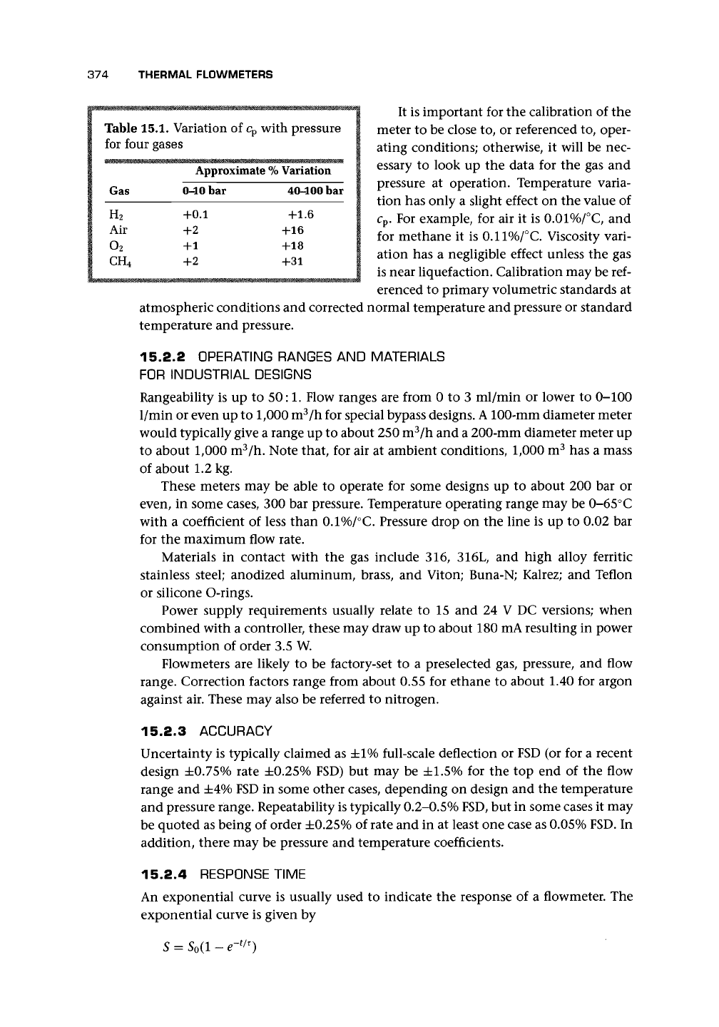
Table 15.1. Variation of c
p
with pressure
for four gases
Gas
H
2
Air
o
2
CH
4
Approximate
%
Variation
0-10 bar
+0.1
+2
+1
+2
40-100 bar
+1.6
+16
+18
+31
374 THERMAL FLOWMETERS
It is important for the calibration of the
meter to be close to, or referenced to, oper-
ating conditions; otherwise, it will be nec-
essary to look up the data for the gas and
pressure at operation. Temperature varia-
tion has only a slight effect on the value of
c
p
. For example, for air it is 0.01%/°C, and
for methane it is 0.11%/°C. Viscosity vari-
ation has a negligible effect unless the gas
is near liquefaction. Calibration may be ref-
erenced to primary volumetric standards at
atmospheric conditions and corrected normal temperature and pressure or standard
temperature and pressure.
15.2.2 OPERATING RANGES
AND
MATERIALS
FOR
INDUSTRIAL DESIGNS
Rangeability is up to 50:1. Flow ranges are from 0 to 3 ml/min or lower to 0-100
1/min or even up to 1,000 m
3
/h for special bypass designs.
A
100-mm diameter meter
would typically give a range up to about 250 m
3
/h and a 200-mm diameter meter up
to about 1,000 m
3
/h. Note that, for air at ambient conditions, 1,000 m
3
has a mass
of about 1.2 kg.
These meters may be able to operate for some designs up to about 200 bar or
even, in some cases, 300 bar pressure. Temperature operating range may be 0-65°C
with a coefficient of less than 0.1%/°C. Pressure drop on the line is up to 0.02 bar
for the maximum flow rate.
Materials in contact with the gas include 316, 316L, and high alloy ferritic
stainless steel; anodized aluminum, brass, and Viton; Buna-N; Kalrez; and Teflon
or silicone O-rings.
Power supply requirements usually relate to 15 and 24 V DC versions; when
combined with a controller, these may draw up to about 180 mA resulting in power
consumption of order 3.5 W.
Flowmeters are likely to be factory-set to a preselected gas, pressure, and flow
range. Correction factors range from about 0.55 for ethane to about 1.40 for argon
against air. These may also be referred to nitrogen.
15.2.3 ACCURACY
Uncertainty is typically claimed as ±1% full-scale deflection or FSD (or for a recent
design ±0.75% rate ±0.25% FSD) but may be ±1.5% for the top end of the flow
range and ±4% FSD in some other cases, depending on design and the temperature
and pressure range. Repeatability is typically 0.2-0.5%
FSD,
but in some cases it may
be quoted as being of order ±0.25% of rate and in at least one case as 0.05%
FSD.
In
addition, there may be pressure and temperature coefficients.
15.2.4 RESPONSE TIME
An exponential curve is usually used to indicate the response of a flowmeter. The
exponential curve is given by
5 = 5
0
(l -
e~
t/T
)
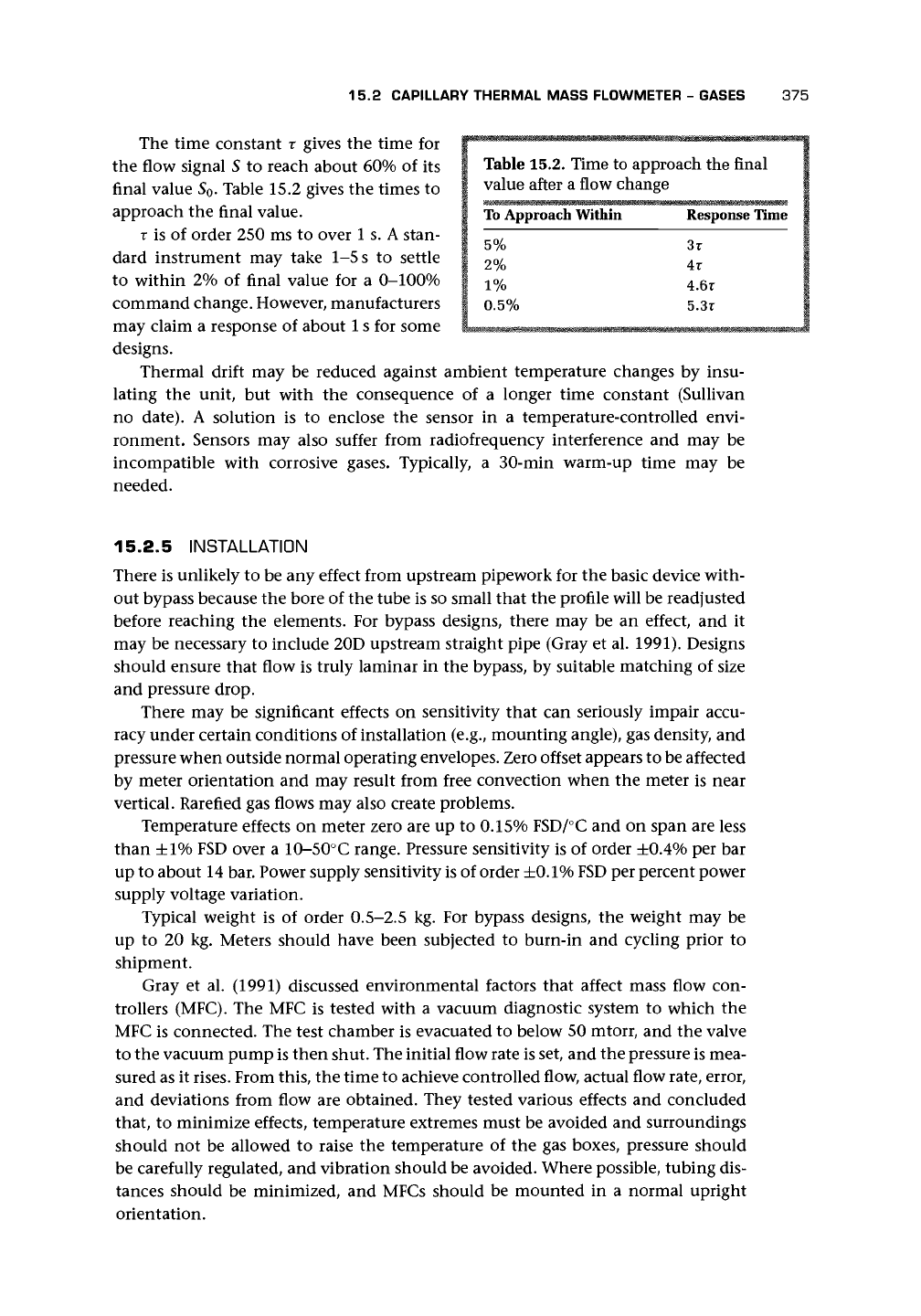
15.2 CAPILLARY THERMAL MASS FLOWMETER - GASES 375
To Approach Within
5%
2%
1%
0.5%
Response Time
3T
4r
4.6r
5.3r
The time constant x gives the time for £
v
'^ " ' "
1
^
i:i
"
v
"
4
' ^ -^ >,/ ,^ ,, ,^,^,
«.*
the flow signal 5 to reach about 60% of its I Table 15.2. Time to approach the final
final value S
o
. Table 15.2 gives the times to i
value after a flow
change
approach the final value.
T
is of order 250 ms to over 1 s. A stan-
dard instrument may take 1-5
s
to settle
to within 2% of final value for a 0-100%
command change. However, manufacturers
may claim a response of about
1
s for some . .
^
-<-.<, ,
designs.
Thermal drift may be reduced against ambient temperature changes by insu-
lating the unit, but with the consequence of a longer time constant (Sullivan
no date). A solution is to enclose the sensor in a temperature-controlled envi-
ronment. Sensors may also suffer from radiofrequency interference and may be
incompatible with corrosive gases. Typically, a 30-min warm-up time may be
needed.
15.2.5 INSTALLATION
There is unlikely to be any effect from upstream pipework for the basic device with-
out bypass because the bore of the tube is so small that the profile will be readjusted
before reaching the elements. For bypass designs, there may be an effect, and it
may be necessary to include 20D upstream straight pipe (Gray et al. 1991). Designs
should ensure that flow is truly laminar in the bypass, by suitable matching of size
and pressure drop.
There may be significant effects on sensitivity that can seriously impair accu-
racy under certain conditions of installation (e.g., mounting angle), gas density, and
pressure when outside normal operating envelopes. Zero offset appears to be affected
by meter orientation and may result from free convection when the meter is near
vertical. Rarefied gas flows may also create problems.
Temperature effects on meter zero are up to 0.15% FSD/°C and on span are less
than ±1% FSD over a 10-50°C range. Pressure sensitivity is of order ±0.4% per bar
up to about 14 bar. Power supply sensitivity is of order
±0.1%
FSD
per percent power
supply voltage variation.
Typical weight is of order 0.5-2.5 kg. For bypass designs, the weight may be
up to 20 kg. Meters should have been subjected to burn-in and cycling prior to
shipment.
Gray et al. (1991) discussed environmental factors that affect mass flow con-
trollers (MFC). The MFC is tested with a vacuum diagnostic system to which the
MFC is connected. The test chamber is evacuated to below 50 mtorr, and the valve
to the vacuum pump is then shut. The initial flow rate is set, and the pressure is mea-
sured as it
rises.
From this, the time to achieve controlled flow, actual flow rate, error,
and deviations from flow are obtained. They tested various effects and concluded
that, to minimize effects, temperature extremes must be avoided and surroundings
should not be allowed to raise the temperature of the gas boxes, pressure should
be carefully regulated, and vibration should be avoided. Where possible, tubing dis-
tances should be minimized, and MFCs should be mounted in a normal upright
orientation.
376 THERMAL FLOWMETERS
15.2.6 APPLICATIONS
CTMFs are most commonly applied to low flows of clean dry gases above their dew-
points (e.g., gas blending, semiconductor industry). Gases quoted by manufacturers
include air, acetylene, ammonia, argon, arsine, nitrogen, butane, carbon dioxide,
carbon monoxide, chlorine, ethane, ethylene, fluorine, Freon 11, Freon 12, Freon
13,
helium, hydrogen, hydrogen sulfide, krypton, methane, neon, nitrous oxide,
oxygen, propane, propylene, silane, and xenon. Examples of problem gases that
have been used with this type of meter include
• BCI3 (boron trichloride) corrosive gas;
• SiCU (silicon tetrachloride) corrosive and low vapor pressure gas;
• CCI4 (carbon tetrachloride) low vapor pressure gas;
• SiH
4
(silane) typical of gases that react and create deposits, resulting in clogging
of flow controllers; and
• WF
6
(tungsten hexafluoride) similar to the handling problems of silane.
The meter may be used with a wide range of gases for processes involving crystal
growth, thermal oxide, diffusion, chemical vapor deposition, sputtering, ion im-
plantation, and plasma etching, and the gases involved will each require a correc-
tion factor against the calibration gas, possibly nitrogen, which may vary between
as low as 0.17 for Freon-C318 (C
4
F
8
) or perfluoropropane, and as high as 1.543 for
krypton. The manufacturer should be asked for the compatibility of any particular
gas and the correction factor (Sullivan no date). In selecting a flowmeter, particular
care should be taken where the inlet pressure is less than atmospheric or has a vapor
pressure less than atmospheric.
15.3 CALIBRATION OF VERY LOW FLOW RATES
One method of calibration of these flowmeters for low flow rates is by means of a
special piston proven A piston moves within a precision glass tube. The piston is
connected to a counterweight by means of a tape that turns an encoder wheel. The
temperature and pressure of the gas are measured while flow is taking place.
Positive displacement devices or piston meters may achieve calibration to an
accuracy of about 0.2% of reading over a range from 0.02 to 30 l/min (Sullivan et al.
no date). The volume flow at standard temperature and pressure (STP), subscript s,
may be obtained from the actual, subscript a, using
Zpa_
va
T
a
p
s
15.4 THERMAL MASS FLOWMETER - LIQUIDS
15.4.1 OPERATION
The diagram in Figure 15.4 shows the layout of a meter with parallel tubes running
between a heating block and a heat-sink block. At the midpoint of each tube is the