Baker R.C. Flow Measurement Handbook: Industrial Designs, Operating Principles, Performance, and Applications
Подождите немного. Документ загружается.

16.3 CHAPTER CONCLUSIONS 397
16.3 CHAPTER CONCLUSIONS
The fuel flow transmitter is an elegant solution but probably suffers, in an age when
mechanical precision is being displaced by solid state, from being a mechanical
rotating device. If the mechanical integrity can be assured and operating life is long
enough, one would expect that sensing of the rotation, torque, and other factors,
with intelligent secondary instrumentation would make it highly accurate.
It is surprising that it has not been exploited for more applications, and even
for gas flow measurement. Presumably the main reason is the preference for a meter
without moving parts.
The logical next step to overcome this would be to move to an oscillating or
vibrating device to achieve the same result. Such devices have been suggested but
may offer little advantage over the Coriolis, which we shall look at next. Any de-
velopments in this device will also be in competition with the rapidly developing
ultrasonic methods that clearly meet many of today's requirements in terms of no
moving parts and predominantly electrical sensors.
The future development of a device such as this, therefore, is unlikely to be
extensive.
CHAPTER
17
Coriolis Flowmeters
17.1 INTRODUCTION
This is one of the most important recent meter developments, and its application
in the next few years is likely to impinge on many areas of industry. Its importance
is recognized by the main national and international advisory bodies (cf. Mandrup-
Jensen 1990 who described initial work in Denmark on pattern approval and ISO
developments).
17.1.1 BACKGROUND
Plache (1977) makes the interesting point that mass cannot be measured without
applying a force on the system and then measuring the resulting acceleration. This
is a point that I have long considered a possible requirement, and it is certainly
supported in the Coriolis meter.
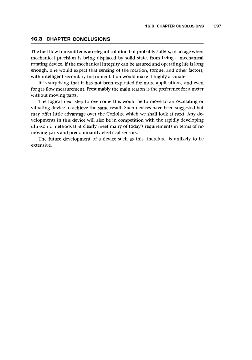
Possibly the first application of the Coriolis effect for mass flow measurement
was proposed by Li and Lee (1953). The meter is shown in Figure
17.1.
The T-piece
flow tube rotated with the outer casing and was linked to it by a torque tube. As the
flow increased, so the T-piece experienced a displacing torque due to the Coriolis
acceleration, and this was measured from the displacement of the T-piece relative to
the main body.
In the Li and Lee meter, the liquid was forced to move radially, and therefore
a force was applied to it through the tube. This force, in turn, was balanced by an
equal and opposite one applied by the liquid to the tube. The force caused the tube
to twist, and the small rotation was sensed to obtain the mass flow rate.
It is interesting to note that Stoll (1978) made no mention of the technology that
was to revolutionize mass flow measurement. Medlock (1989) referred to several de-
signs that, although not identified as dependent on the Coriolis effect, have a very
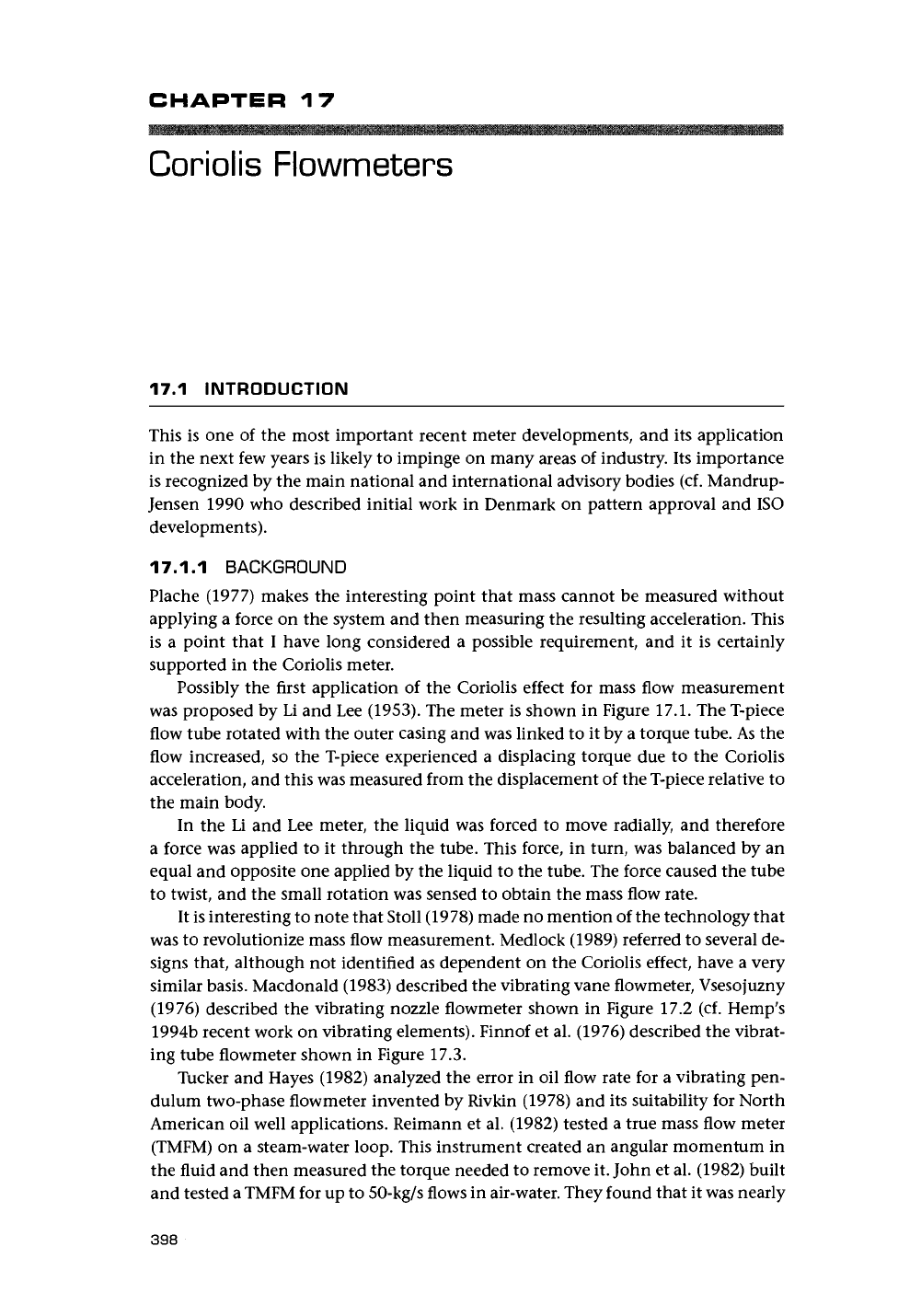
similar basis. Macdonald (1983) described the vibrating vane flowmeter, Vsesojuzny
(1976) described the vibrating nozzle flowmeter shown in Figure 17.2 (cf. Hemp's
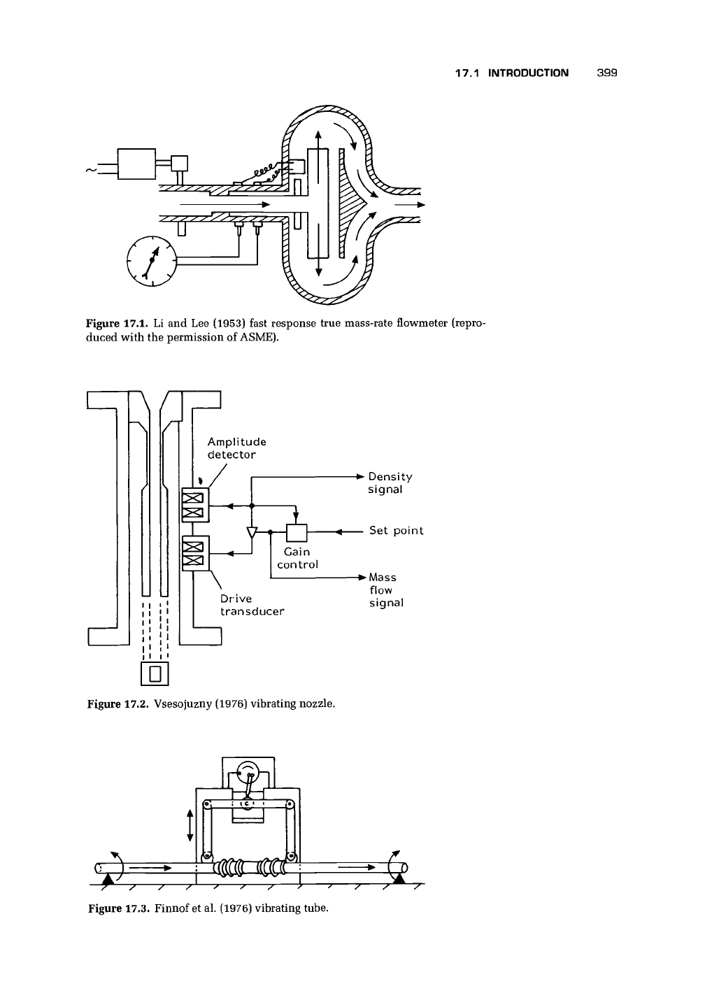
1994b recent work on vibrating elements). Finnof et al. (1976) described the vibrat-
ing tube flowmeter shown in Figure 17.3.
Tucker and Hayes (1982) analyzed the error in oil flow rate for a vibrating pen-
dulum two-phase flowmeter invented by Rivkin (1978) and its suitability for North
American oil well applications. Reimann et al. (1982) tested a true mass flow meter
(TMFM) on a steam-water loop. This instrument created an angular momentum in
the fluid and then measured the torque needed to remove it. John et al. (1982) built
and tested a TMFM for up to 50-kg/s flows in air-water. They found that it was nearly
398
17.1 INTRODUCTION 399
Figure 17.1. Li and Lee (1953) fast response true mass-rate flowmeter (repro-
duced with the permission of ASME).
A /
Amplitude
detector
-• Density
signal
\
Set point
Cain
control
Drive
transducer
flow
signal
•
Figure 17.2. Vsesojuzny (1976) vibrating nozzle.
OTT
ill
Figure 17.3. Finnof et al. (1976) vibrating tube.
400
CORIOLIS FLOWMETERS
independent of the flow regime and had an overall measurement uncertainty of less
than ±1.5% of full-scale deflection up to 20% mass fraction of air, although they
observed a shift in the characteristic of
2.5%
for mass fractions of air above 1%. This
was an impressive performance. However the instrument is unlikely to be attractive
for most applications due to the requirement to drive a rotor and the consequent
design and maintenance problems.
Dimaczek et al. (1994) suggested the use of a radial turbine type wheel to create
a Coriolis effect meter for dosing gas-solid flows. They claimed that a measurement
uncertainty of ±1% rate was achieved, and that it was used for flows of coal dust,
quartz sand, feldspar, plastic granulates, and foodstuffs.
Decker's (1960) design can be explained in terms of a modern Coriolis meter.
It appears to have been the meter developed by Finnof et al. (1976, cf. Smith and
Cage 1985), which was first successfully launched into the market in 1976 (Plache
1977,
cf. 1980) according to Medlock (1989). Tullis and Smith (1979) reported early
tests on meters of g, \, and 1 in., which were promising and led to optimism for
wide application of the meters to liquids, gases, and two-phase flows.
17.1.2 QUALITATIVE DESCRIPTION OF OPERATION
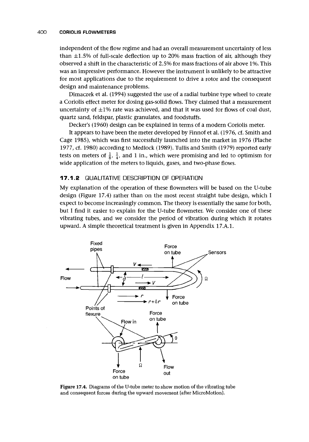
My explanation of the operation of these flowmeters will be based on the U-tube
design (Figure 17.4) rather than on the most recent straight tube design, which I
expect to become increasingly common. The theory is essentially the same for both,
but I find it easier to explain for the U-tube flowmeter. We consider one of these
vibrating tubes, and we consider the period of vibration during which it rotates
upward. A simple theoretical treatment is given in Appendix
17.A.1.
Fixed
pipes
Force
on tube
Flow
Sensors
Force
on tube
Figure 17.4. Diagrams of the U-tube meter to show motion of the vibrating tube
and consequent forces during the upward movement (after MicroMotion).
17.1 INTRODUCTION
401
Flow
Magnet
position
sensors
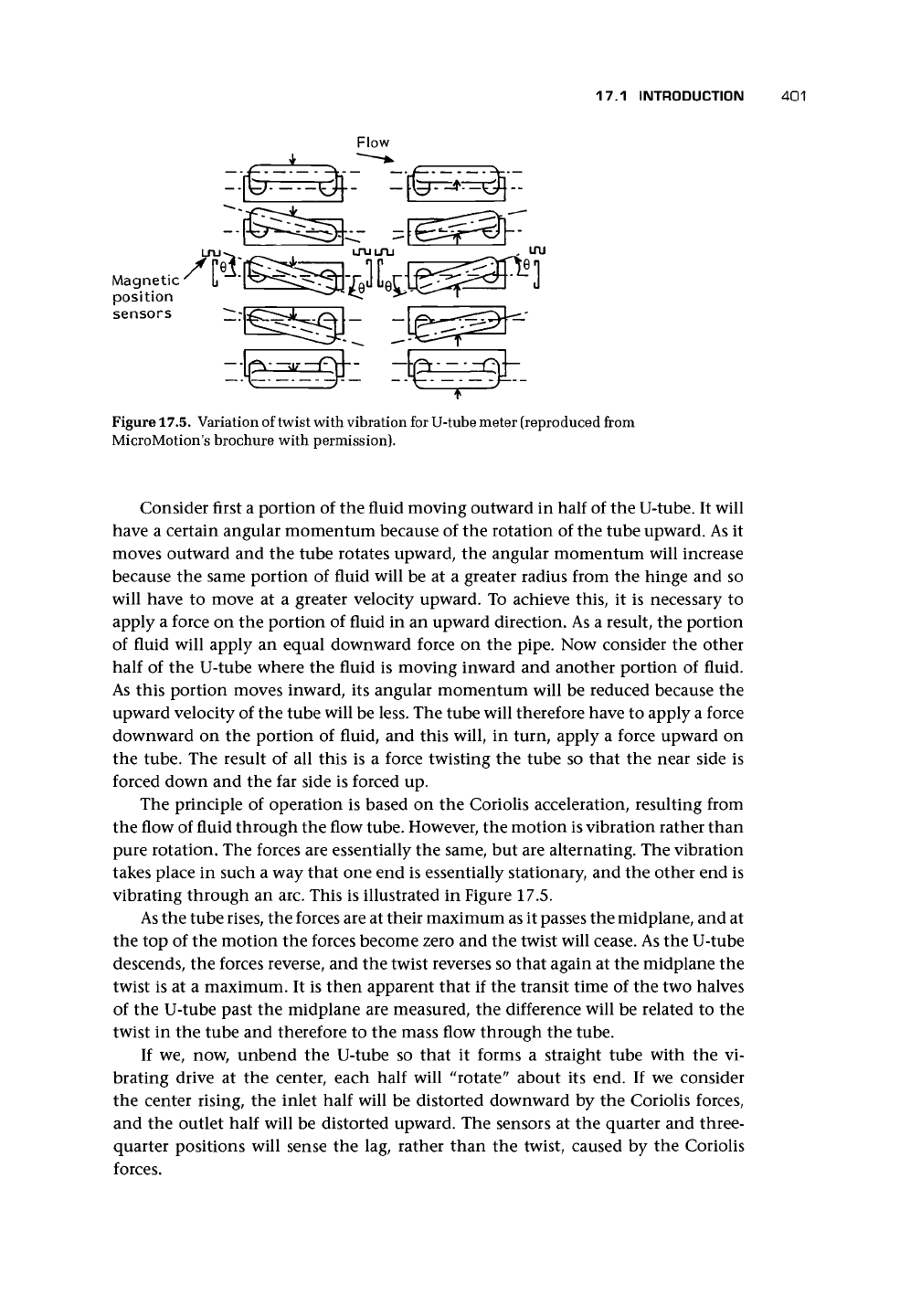
Figure 17.5. Variation of twist with vibration for U-tube meter (reproduced from
MicroMotion's brochure with permission).
Consider first a portion of the fluid moving outward in half of the U-tube. It will
have a certain angular momentum because of the rotation of the tube upward. As it
moves outward and the tube rotates upward, the angular momentum will increase
because the same portion of fluid will be at a greater radius from the hinge and so
will have to move at a greater velocity upward. To achieve this, it is necessary to
apply a force on the portion of fluid in an upward direction. As a result, the portion
of fluid will apply an equal downward force on the pipe. Now consider the other
half of the U-tube where the fluid is moving inward and another portion of fluid.
As this portion moves inward, its angular momentum will be reduced because the
upward velocity of the tube will be less. The tube will therefore have to apply a force
downward on the portion of fluid, and this will, in turn, apply a force upward on
the tube. The result of all this is a force twisting the tube so that the near side is
forced down and the far side is forced up.
The principle of operation is based on the Coriolis acceleration, resulting from
the flow of fluid through the flow tube. However, the motion is vibration rather than
pure rotation. The forces are essentially the same, but are alternating. The vibration
takes place in such a way that one end is essentially stationary, and the other end is
vibrating through an arc. This is illustrated in Figure 17.5.
As
the tube
rises,
the forces are at their maximum as it passes the midplane, and at
the top of the motion the forces become zero and the twist will cease. As the U-tube
descends, the forces reverse, and the twist reverses so that again at the midplane the
twist is at a maximum. It is then apparent that if the transit time of the two halves
of the U-tube past the midplane are measured, the difference will be related to the
twist in the tube and therefore to the mass flow through the tube.
If we, now, unbend the U-tube so that it forms a straight tube with the vi-
brating drive at the center, each half will "rotate" about its end. If we consider
the center rising, the inlet half will be distorted downward by the Coriolis forces,
and the outlet half will be distorted upward. The sensors at the quarter and three-
quarter positions will sense the lag, rather than the twist, caused by the Coriolis
forces.
402 C0RI0LIS FLOWMETERS
17.1.3 EXPERIMENTAL INVESTIGATIONS
Adiletta et al.
(1993,
cf. Cascetta et al. 1989a, 1989b) described a prototype that
sought to overcome the limitations of commercial instruments' dependence on tube
deformation by
a. a system of rigid tubes,
b.
a separate elastic suspension, and
c. electromagnetic drive and capacitance transducers to infer the twist.
Their design appeared to be affected little by external vibrations.
Sultan (1992) described a single-tube meter of 28-mm OD built for laboratory
experiments. It had a drive coil in the center of the 1410-mm-long straight pipe and
two symmetrically positioned detector coils. For his rig, a change of water tempera-
ture of about 14°C caused a zero flow calibration shift equivalent to about 0.4 m/s
(maximum flow rates tested were about 5.6 m/s). He accounted for this as being
due to differential thermal expansion and the consequent differential characteris-
tics.
This will lead to frequency change. Tube temperature change will also cause
a change in the modulus of elasticity and hence a frequency change. Sultan also
showed that a pump in the flow circuit caused a zero fluctuation due to vibration
equivalent to a flow of about ±0.1 m/s.
Kolahi et
al.
(1994) described a prototype meter with similarities to the MicroMo-
tion meter having two U-tubes. The design was very versatile in terms of component
changes. Optical, capacitive, and inductive sensors could be used. It was also possible
to tune it so as to amplify the torsional amplitude by up to 100 times.
Hagenmeyer et
al.
(1994) reported a design of
a
single-tube, compact Coriolis me-
ter operating in a hoop mode and claimed that experimental results were promising.
17.2 INDUSTRIAL DESIGNS
The MicroMotion meter was the first to appear in 1981 and resulted from patents
filed in 1975, 1977, and 1978 (cf. Wilier 1978 and Smith 1978). The initial device
consisted of a single U-tube.
A
recent paper by Tsutsui and Yamikawa (1993) seemed
to be using one tube plus a resonance vibrator as in the early MicroMotion meter.
Twin tubes were introduced in model D in 1983. The main features of this meter
are a single inlet splitting into the two tubes, a drive system to cause the tubes to
vibrate, a pair of sensors to detect the movement of the tubes past the midplane, and
a strong point around which the tubes vibrate in opposition. In some meters, the
outer cover forms a pressure vessel so that, if the tubes fail, the fluid will be contained.
Failure should not be due to fatigue, because manufacturers should design so that
tubes will not fail due to cyclic stressing. Tube failure almost always occurs due to
corrosive stressing.
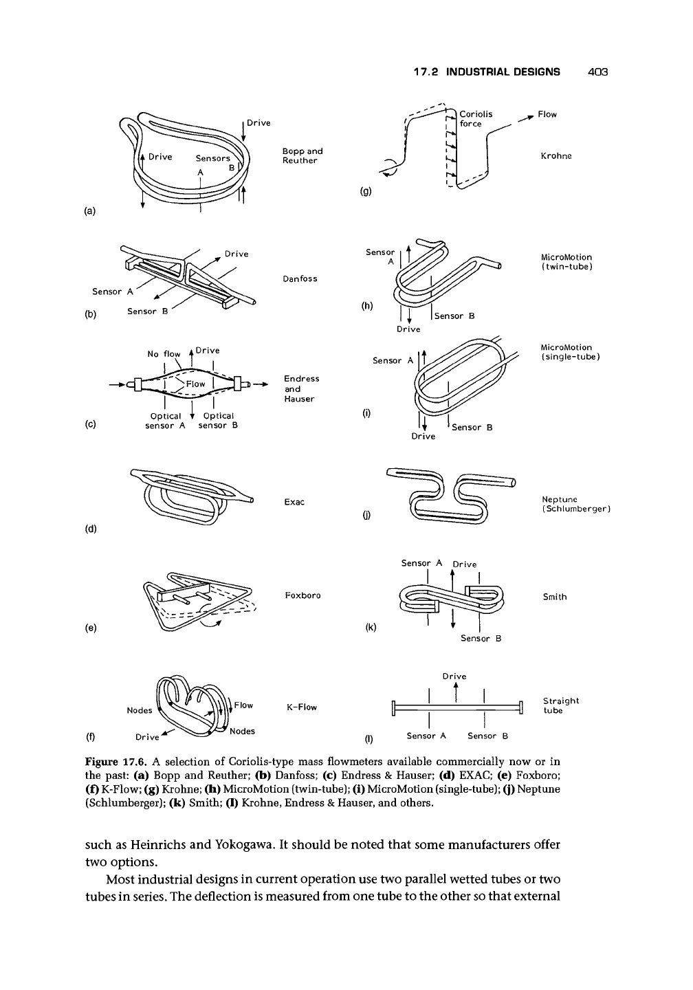
Several designs followed MicroMotion and a selection of these, some no longer
available, are shown diagrammatically in Figure 17.6 based on my understanding
of the manufacturers' brochures. Apart from those shown [Bopp & Reuther, Dan-
foss,
Endress & Hauser, EXAC, Foxboro, K-Flow, Krohne, MicroMotion, Neptune
(Schlumberger), and Smith], there maybe other manufacturers of this type of meter,
17.2 INDUSTRIAL DESIGNS 403
(a)
Drive
Bopp and
Reuther
Krohne
Drive
Drive
(C)
Danfoss
Optical T Optical
sensor A sensor B
Endress
and
Hauser
(i)
Sensor B
MicroMotion
(twin-tube)
MicroMotion
(single-tube)
Drive
(d)
Exac
0)
Neptune
(Schlumberger)
(e)
Foxboro
(k)
Sensor A Drive
Sensor B
Smith
(f)
Nodes
Drive
K-Flow
Nodes
(I)
Sensor A Sensor B
Straight
tube
Figure 17.6. A selection of Coriolis-type mass flowmeters available commercially now or in
the past: (a) Bopp and Reuther; (b) Danfoss; (c) Endress
&
Hauser; (d) EXAC; (e) Foxboro;
(f) K-Flow; (g) Krohne; (h) MicroMotion (twin-tube); (i) MicroMotion (single-tube); (j) Neptune
(Schlumberger); (k) Smith; (1) Krohne, Endress
&
Hauser, and others.
such as Heinrichs and Yokogawa. It should be noted that some manufacturers offer
two options.
Most industrial designs in current operation use two parallel wetted tubes or two
tubes in series. The deflection is measured from one tube to the other so that external
404 C0RI0LIS FLOWMETERS
vibrations are largely eliminated and the measured shift between the tubes has the
effect of adding the flows in the two tubes even if the flow split is not equal.
Single-tube versions (e.g., Hussain and Farrant 1994) are beginning to be intro-
duced, and these are likely to be an increasingly attractive option for the future
(Reider and Drahm 1996, Yamashita 1996). At present, these may be offered as a
second design by some manufacturers (cf. Stansfeld et al. 1988, Harrie 1991 for an
earlier design).
17.2.1 PRINCIPAL DESIGN COMPONENTS
Flow Tubes
The deflection of the tubes is sensed from one tube to the other in twin-tube versions
or between tube and outer compensating tube in single-tube versions. This elimi-
nates,
to a large extent, external vibrations. The tubes are mounted to isolate them
from external vibration and are designed to optimize phase shift between sensor
signals and to minimize pressure loss. Wagner (1988) discussed trade-offs for tube
selection. For instance, by lengthening the meter tube, vibration of the tube is easier,
stresses are reduced, and twist and Coriolis force increase. However, this is at the cost
of greater weight and pressure drop.
The problem of corrosion is a reason why some manufacturers use an outer
containment vessel around the vibrating tubes in case of tube failure.
Foxboro has introduced a technique called antiphase excitation, which uses a
double driver system to produce a rotating motion on the tube essentially at the
flattened bottom of the U-tube. In this way, the stresses are greatly reduced because
the vibration is away from the pipe joints. This appears to be similar to the Bopp &
Reuther and the Krohne designs. Watt (1990) described work on the computation
of pipe stresses.
Drive Mechanisms
Drive mechanisms are most commonly electromagnetically excited to oscillate at
the chosen frequency. In some cases, this is the natural (resonant) frequency; in
others, it is a harmonic of the natural frequency. Higher frequencies are claimed to
reduce the effect of external disturbances by introducing free nodes of vibration and
by working farther above the most common surrounding frequencies. The control
circuit then keeps the oscillation at the chosen frequency. For high viscosity or
density, additional power may be required in the drive.
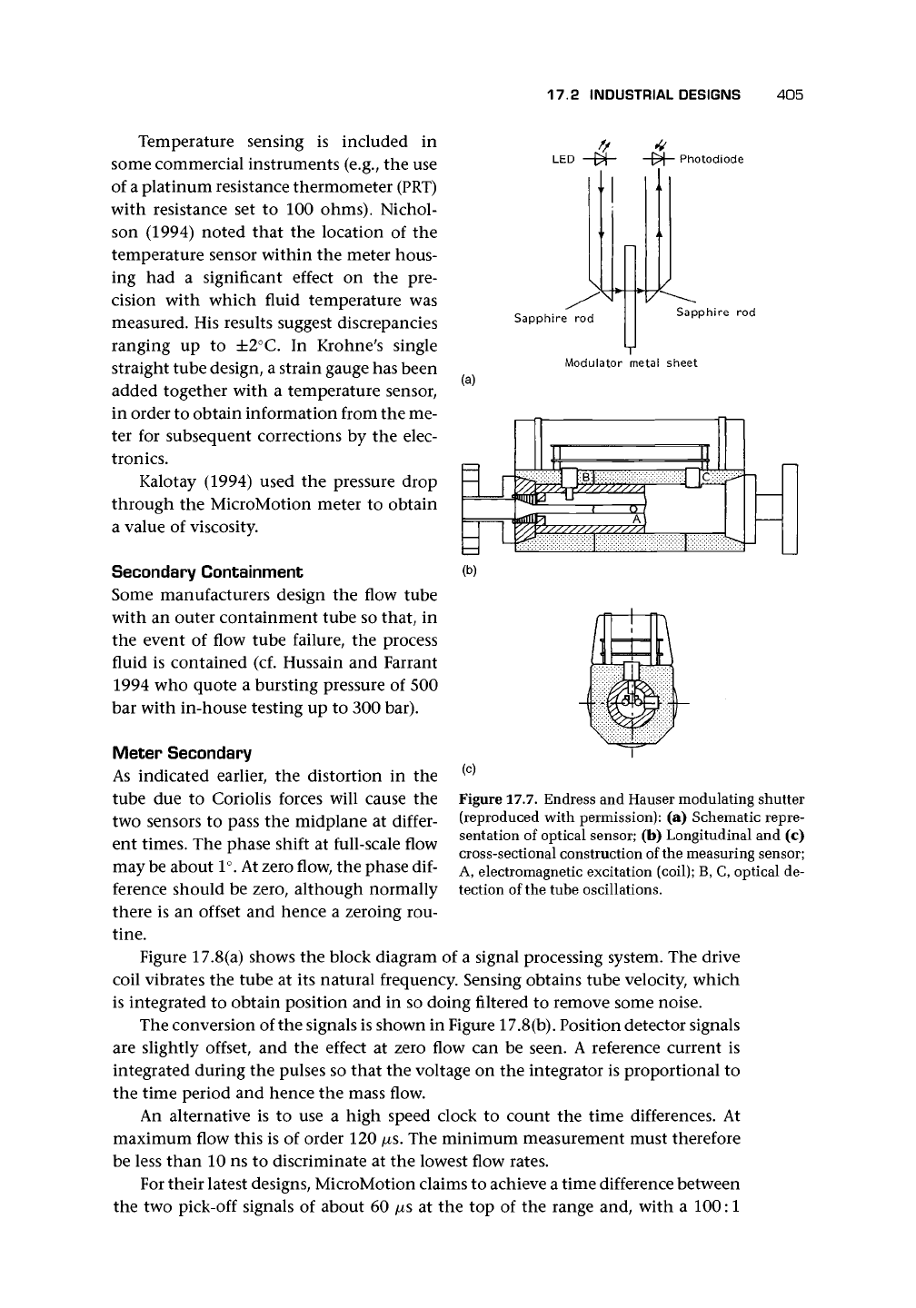
Sensor Types
In meters with twin tubes, the sensor usually measures the displacement between
the two tubes, thus eliminating any common spurious vibrations. One method used
in several designs has a coil on one tube and a magnet on the other. The relative
velocity causes a voltage to be generated in the coil, and, in order to obtain po-
sition, this signal is integrated. Another method (Vogtlin and Tschabold, Endress
& Hauser) is optical and uses an arrangement of photodiodes and a modulating
shutter (Figure 17.7). "Small plates acting as shutters are attached to the tubes
... leaving a defined gap between each pair. The shutter changes as the two tubes os-
cillate in phase opposition. ... Infrared light is beamed from a light-emitting diode
into a sapphire rod with face ground to a 45° angle. Thus the quantity of light is
modulated ... and converted into alternating electric current. ... "
17.2 INDUSTRIAL DESIGNS 405
LED [> -[X— Photodiode
Sapphire rod
Sapphire rod
Modulator metal sheet
(a)
Temperature sensing is included in
some commercial instruments (e.g., the use
of a platinum resistance thermometer (PRT)
with resistance set to 100 ohms). Nichol-
son (1994) noted that the location of the
temperature sensor within the meter hous-
ing had a significant effect on the pre-
cision with which fluid temperature was
measured. His results suggest discrepancies
ranging up to ±2°C. In Krohne's single
straight tube design, a strain gauge has been
added together with a temperature sensor,
in order to obtain information from the me-
ter for subsequent corrections by the elec-
tronics.
Kalotay (1994) used the pressure drop
through the MicroMotion meter to obtain
a value of viscosity.
Secondary Containment
Some manufacturers design the flow tube
with an outer containment tube so that, in
the event of flow tube failure, the process
fluid is contained (cf. Hussain and Farrant
1994 who quote a bursting pressure of 500
bar with in-house testing up to 300 bar).
Meter Secondary
As indicated earlier, the distortion in the
tube due to Coriolis forces will cause the
two sensors to pass the midplane at differ-
ent times. The phase shift at full-scale flow
may be about
1°.
At zero flow, the phase dif-
ference should be zero, although normally
there is an offset and hence a zeroing rou-
tine.
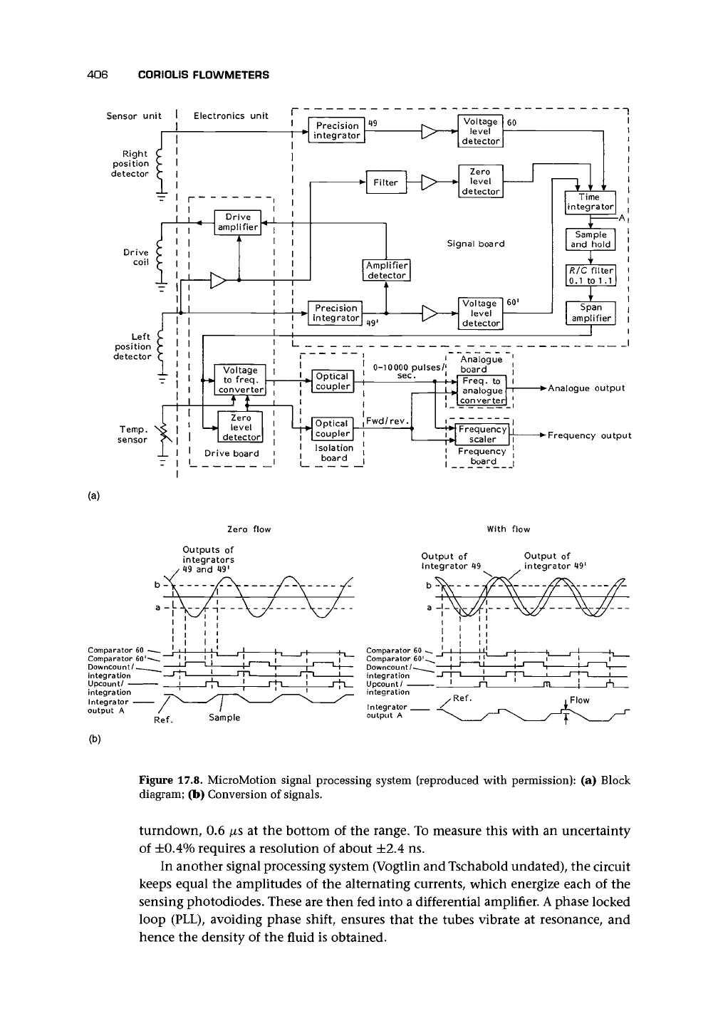
Figure 17.8(a) shows the block diagram of a signal processing system. The drive
coil vibrates the tube at its natural frequency. Sensing obtains tube velocity, which
is integrated to obtain position and in so doing filtered to remove some noise.
The conversion of the signals is shown in Figure 17.8(b). Position detector signals
are slightly offset, and the effect at zero flow can be seen. A reference current is
integrated during the pulses so that the voltage on the integrator is proportional to
the time period and hence the mass flow.
An alternative is to use a high speed clock to count the time differences. At
maximum flow this is of order 120
/^s.
The minimum measurement must therefore
be less than 10 ns to discriminate at the lowest flow rates.
For their latest designs, MicroMotion claims to achieve a time difference between
the two pick-off signals of about 60 /xs at the top of the range and, with a 100:1
(c)
Figure 17.7. Endress and Hauser modulating shutter
(reproduced with permission): (a) Schematic repre-
sentation of optical sensor; (b) Longitudinal and (c)
cross-sectional construction of the measuring sensor;
A, electromagnetic excitation (coil); B, C, optical de-
tection of the tube oscillations.
406 C0RI0LIS FLOWMETERS
Sensor unit
Frequency output
(a)
Zero flow With flow
Outputs of
integrators
*
49
and 49'
Output of
integrator 49
Output of
integrator 49'
Ref.
Sample
Comparator 60
Comparator 60
Downcount/
integration
Upcount/
(b)
Figure 17.8. MicroMotion signal processing system (reproduced with permission): (a) Block
diagram; (b) Conversion of signals.
turndown, 0.6 /xs at the bottom of the range. To measure this with an uncertainty
of ±0.4% requires a resolution of about ±2.4 ns.
In another signal processing system (Vogtlin and Tschabold undated), the circuit
keeps equal the amplitudes of the alternating currents, which energize each of the
sensing photodiodes. These are then fed into a differential amplifier.
A
phase locked
loop (PLL), avoiding phase shift, ensures that the tubes vibrate at resonance, and
hence the density of the fluid is obtained.