Baker R.C. Flow Measurement Handbook: Industrial Designs, Operating Principles, Performance, and Applications
Подождите немного. Документ загружается.

15.4 THERMAL MASS FLOWMETER - LIQUIDS 377
Body
(Heatsink) I
I
Interface -1
A
I-
Tidy
Sensor zone 2
B
T
4
Sensor zone 1
—i
1
>J
Ttop
Guideline
—
H
Top
(Heater)
Process wetted
part316LSS
Ttop -
Tbody
= (20°C for Model 5881,10°C for Model 5882).
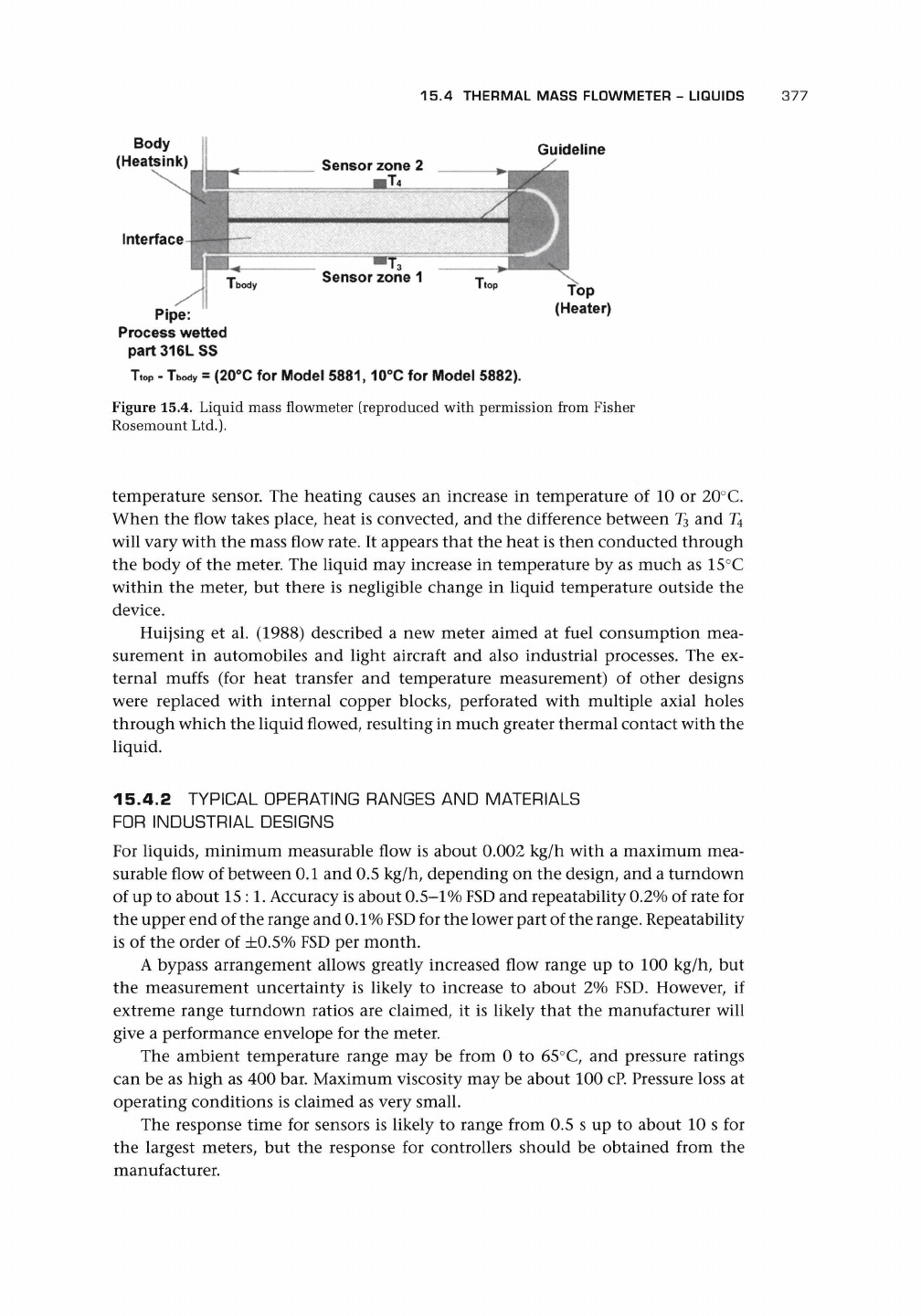
Figure 15.4. Liquid mass flowmeter (reproduced with permission from Fisher
Rosemount Ltd.).
temperature sensor. The heating causes an increase in temperature of 10 or 20°C.
When the flow takes place, heat is converted, and the difference between T
3
and T
4
will vary with the mass flow rate. It appears that the heat is then conducted through
the body of the meter. The liquid may increase in temperature by as much as 15°C
within the meter, but there is negligible change in liquid temperature outside the
device.
Huijsing et al. (1988) described a new meter aimed at fuel consumption mea-
surement in automobiles and light aircraft and also industrial processes. The ex-
ternal muffs (for heat transfer and temperature measurement) of other designs
were replaced with internal copper blocks, perforated with multiple axial holes
through which the liquid flowed, resulting in much greater thermal contact with the
liquid.
15.4.2 TYPICAL OPERATING RANGES AND MATERIALS
FOR INDUSTRIAL DESIGNS
For liquids, minimum measurable flow is about 0.002 kg/h with a maximum mea-
surable flow of between 0.1 and 0.5 kg/h, depending on the design, and a turndown
of up to about
15:1.
Accuracy is about
0.5-1%
FSD
and repeatability 0.2% of rate for
the upper end of the range and
0.1%
FSD
for the lower part of the
range.
Repeatability
is of the order of ±0.5% FSD per month.
A bypass arrangement allows greatly increased flow range up to 100 kg/h, but
the measurement uncertainty is likely to increase to about 2% FSD. However, if
extreme range turndown ratios are claimed, it is likely that the manufacturer will
give a performance envelope for the meter.
The ambient temperature range may be from 0 to 65°C, and pressure ratings
can be as high as 400 bar. Maximum viscosity may be about 100
cP.
Pressure loss at
operating conditions is claimed as very small.
The response time for sensors is likely to range from 0.5 s up to about 10 s for
the largest meters, but the response for controllers should be obtained from the
manufacturer.
378 THERMAL FLOWMETERS
15.4.3
INSTALLATION
Pipe size connections range from
^ to \
in. (about 1.5-6 mm) with materials of
stainless steel and seals of
Buna-N,
Viton,
PTFE,
or
Kalrez.
Process temperature change
can cause +0.02%/°C, and ambient temperature effects can cause up to +0.03%/°C.
15.4.4
APPLICATIONS
It may
be
suitable
for
measurement
of
very low flow rates
of
toxic, corrosive,
and volatile liquids (liquefied gases under pressure), catalysts
in
petrochemicals,
pigments
in
paints, reagents
in
pharmaceuticals, flavorants, enzymes, antibiotics
in food, odorants into natural gas, titanium chloride closing into furnaces for hard-
ening metals, corrosion inhibitors in pipes, and reagents in fermenters. It also may
offer
a
means
for
controlling and measuring very low flows
in
laboratories con-
cerned with microfiltration, measurement of porosity of rocks, fuel consumption,
lubrication, gas/vapor mixtures, and chromatograph flows, as well as controlling the
injection of additives (catalyzers) into industrial reactors.
15.5 INSERTION AND IN-LINE THERMAL MASS FLOWMETERS
The in-line thermal mass flowmeters (ITMFs) represent an alternative design concept
to the CTMF, and both insertion and in-line versions appear to be aimed at the same
goal
-
mass flow measurement of gases in pipes and ducts.
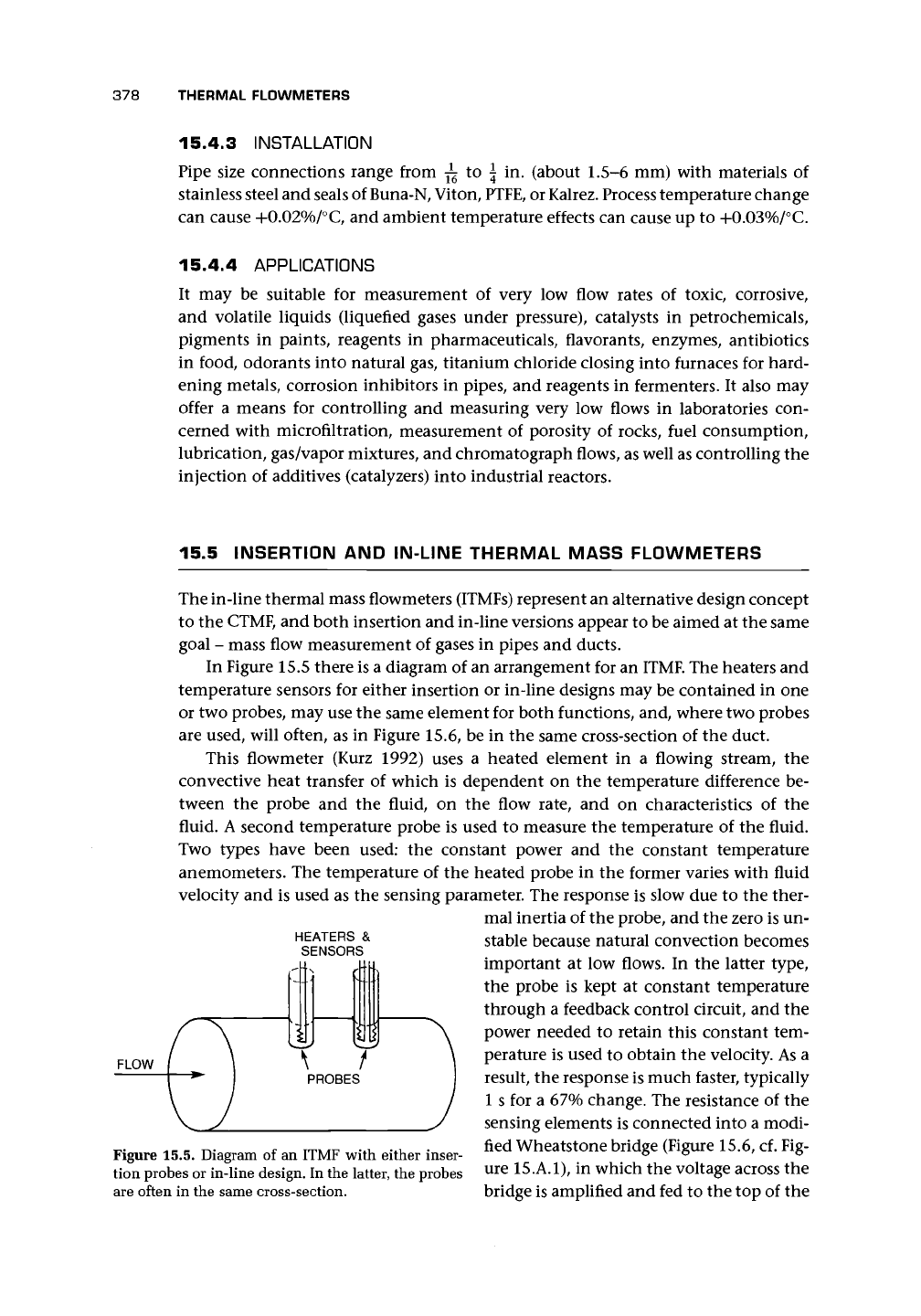
In Figure 15.5 there is a diagram of an arrangement for an
ITMF.
The heaters and
temperature sensors for either insertion or in-line designs may be contained in one
or two probes, may use the same element for both functions, and, where two probes
are used, will often, as in Figure 15.6, be in the same cross-section of the duct.
This flowmeter (Kurz 1992) uses
a
heated element
in a
flowing stream,
the
convective heat transfer of which is dependent on the temperature difference be-
tween the probe and
the
fluid,
on the
flow rate, and
on
characteristics
of
the
fluid. A second temperature probe is used to measure the temperature of the fluid.
Two types have been used:
the
constant power and
the
constant temperature
anemometers. The temperature of the heated probe in the former varies with fluid
velocity and is used as the sensing parameter. The response is slow due to the ther-
mal inertia of the probe, and the zero is un-
stable because natural convection becomes
important
at
low flows.
In
the latter type,
the probe
is
kept
at
constant temperature
through a feedback control circuit, and the
power needed to retain this constant tem-
perature is used to obtain the velocity. As a
result, the response is much faster, typically
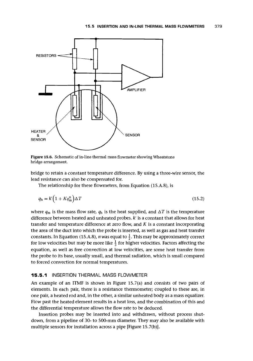
1 s for a 67% change. The resistance of the
sensing elements is connected into a modi-
fied Wheatstone bridge (Figure 15.6, cf. Fig-
ure 15.A.I), in which the voltage across the
bridge is amplified and fed to the top of the
HEATERS
&
SENSORS
Figure 15.5. Diagram of an ITMF with either inser-
tion probes or in-line design. In the latter, the probes
are often in the same cross-section.
15.5 INSERTION AND IN-LINE THERMAL MASS FLOWMETERS 379
RESISTORS
SENSOR
Figure 15.6. Schematic
of
in-line thermal mass flowmeter showing Wheatstone
bridge arrangement.
bridge
to
retain
a
constant temperature difference. By using
a
three-wire sensor,
the
lead resistance
can
also
be
compensated
for.
The relationship
for
these flowmeters, from Equation (15.A.8),
is
(15.2)
where
q
m
is the
mass flow rate,
q^ is the
heat supplied,
and AT is the
temperature
difference between heated
and
unheated probes,
k' is a
constant that allows
for
heat
transfer
and
temperature difference
at
zero flow,
and K is a
constant incorporating
the area
of the
duct into which
the
probe
is
inserted, as well
as
gas
and
heat transfer
constants.
In
Equation (15.A.8), n was equal
to \.
This may be approximately correct
for low velocities
but
may
be
more like
\ for
higher velocities. Factors affecting
the
equation,
as
well
as
free convection
at low
velocities,
are
some heat transfer from
the probe
to its
base, usually small,
and
thermal radiation, which
is
small compared
to forced convection
for
normal temperatures.
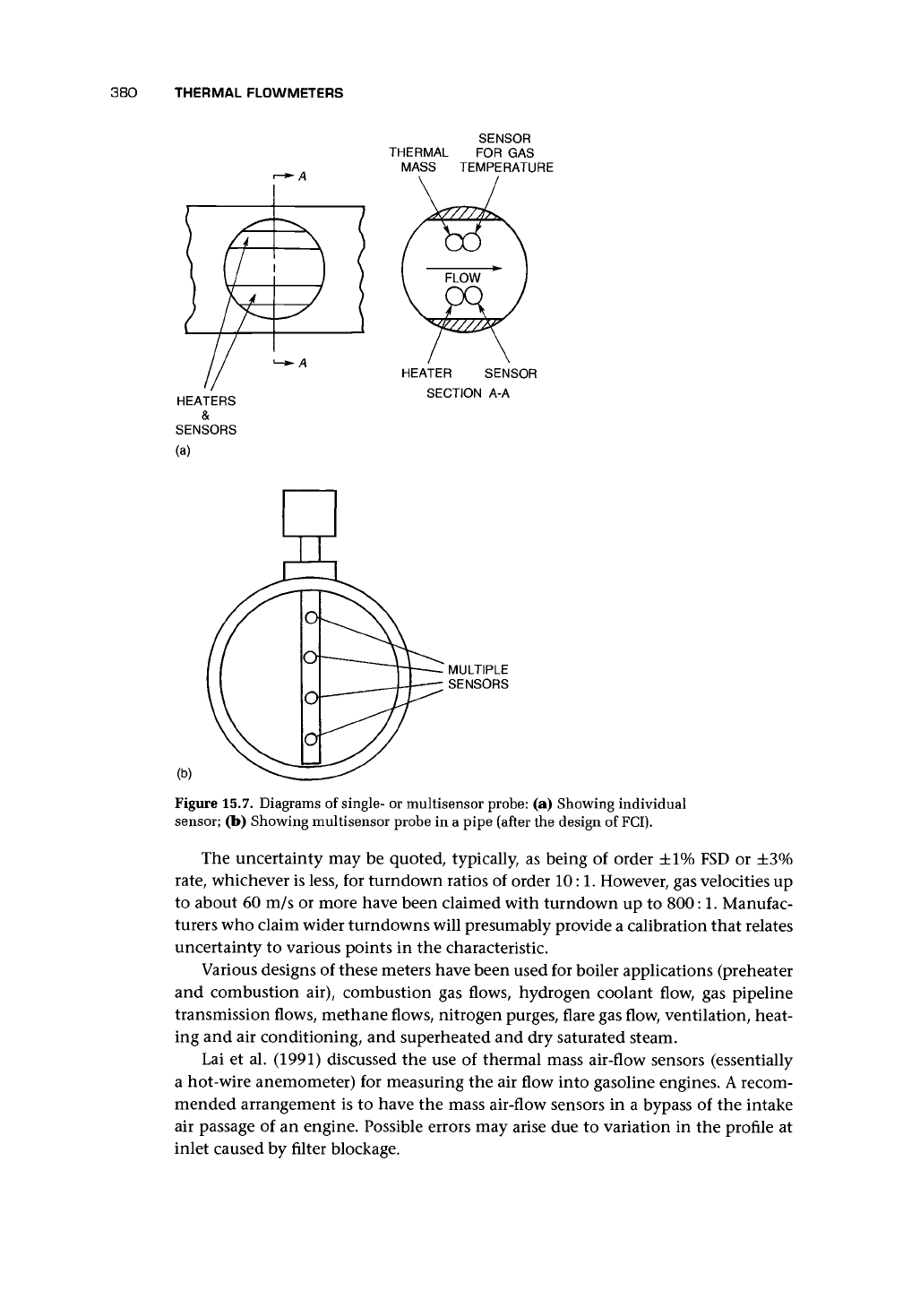
15.5.1 INSERTION THERMAL MASS FLOWMETER
An example
of an
ITMF
is
shown
in
Figure 15.7(a)
and
consists
of two
pairs
of
elements.
In
each pair, there
is a
resistance thermometer; coupled
to
these
are, in
one pair,
a
heated
rod
and,
in the
other,
a
similar unheated body as
a
mass equalizer.
Flow past
the
heated element results
in a
heat loss,
and the
combination
of
this
and
the differential temperature allows
the
flow rate
to be
deduced.
Insertion probes
may be
inserted into
and
withdrawn, without process shut-
down, from
a
pipeline
of
30-
to
500-mm diameter. They
may
also
be
available with
multiple sensors
for
installation across
a
pipe [Figure 15.7(b)].
380
THERMAL FLOWMETERS
SENSOR
THERMAL FOR GAS
MASS TEMPERATURE
HEATER SENSOR
SECTION A-A
(b)
Figure 15.7. Diagrams of single- or multisensor probe: (a) Showing individual
sensor; (b) Showing multisensor probe in a pipe (after the design of FCI).
The uncertainty may be quoted, typically, as being of order ±1% FSD or ±3%
rate,
whichever is less, for turndown ratios of order 10:1. However, gas velocities up
to about 60 m/s or more have been claimed with turndown up to
800:1.
Manufac-
turers who claim wider turndowns will presumably provide a calibration that relates
uncertainty to various points in the characteristic.
Various designs of these meters have been used for boiler applications (preheater
and combustion air), combustion gas flows, hydrogen coolant flow, gas pipeline
transmission flows, methane flows, nitrogen purges, flare gas flow, ventilation, heat-
ing and air conditioning, and superheated and dry saturated steam.
Lai et al. (1991) discussed the use of thermal mass air-flow sensors (essentially
a hot-wire anemometer) for measuring the air flow into gasoline engines. A recom-
mended arrangement is to have the mass air-flow sensors in a bypass of the intake
air passage of an engine. Possible errors may arise due to variation in the profile at
inlet caused by filter blockage.
15.5 INSERTION AND IN-LINE THERMAL MASS FLOWMETERS
381
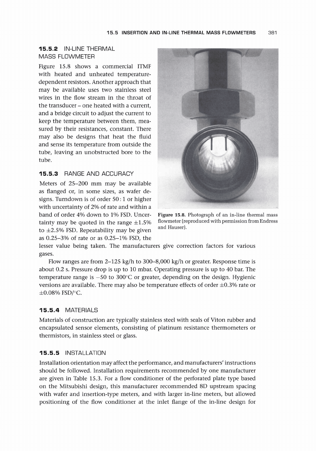
15.5.2 IN-LINE THERMAL
MASS FLOWMETER
Figure 15.8 shows a commercial ITMF
with heated and unheated temperature-
dependent resistors. Another approach that
may be available uses two stainless steel
wires in the flow stream in the throat of
the transducer - one heated with a current,
and a bridge circuit to adjust the current to
keep the temperature between them, mea-
sured by their resistances, constant. There
may also be designs that heat the fluid
and sense its temperature from outside the
tube,
leaving an unobstructed bore to the
tube.
15.5.3 RANGE AND ACCURACY
Meters of 25-200 mm may be available
as flanged or, in some sizes, as wafer de-
signs.
Turndown is of order 50:1 or higher
with uncertainty of 2% of rate and within a
band of order 4% down to 1% FSD. Uncer-
tainty may be quoted in the range ±1.5%
to ±2.5% FSD. Repeatability may be given
as 0.25-3% of rate or as
0.25-1%
FSD, the
lesser value being taken. The manufacturers give correction factors for various
gases.
Flow ranges are from 2-125 kg/h to 300-8,000 kg/h or greater. Response time is
about 0.2 s. Pressure drop is up to 10 mbar. Operating pressure is up to 40 bar. The
temperature range is —50 to 300°C or greater, depending on the design. Hygienic
versions are available. There may also be temperature effects of order ±0.3% rate or
±0.08%
FSD/°C.
Figure 15.8. Photograph of an in-line thermal mass
flowmeter (reproduced with permission from Endress
and Hauser).
15.5.4 MATERIALS
Materials of construction are typically stainless steel with seals of Viton rubber and
encapsulated sensor elements, consisting of platinum resistance thermometers or
thermistors, in stainless steel or glass.
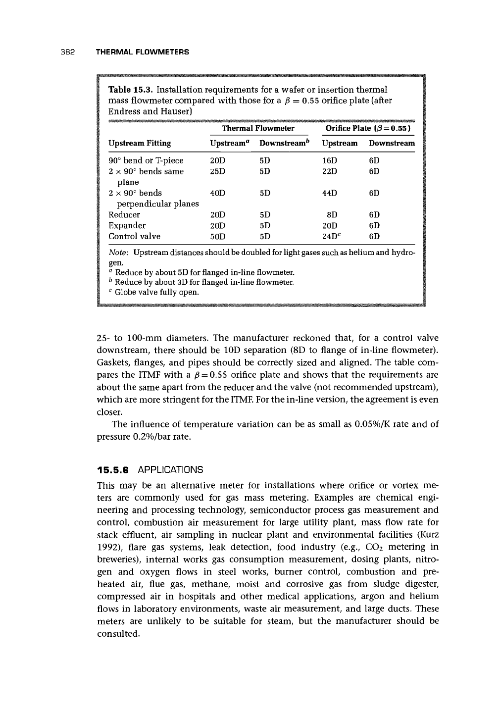
15.5.5 INSTALLATION
Installation orientation may affect the performance, and manufacturers' instructions
should be followed. Installation requirements recommended by one manufacturer
are given in Table 15.3. For a flow conditioner of the perforated plate type based
on the Mitsubishi design, this manufacturer recommended 8D upstream spacing
with wafer and insertion-type meters, and with larger in-line meters, but allowed
positioning of the flow conditioner at the inlet flange of the in-line design for
382
THERMAL FLOWMETERS
Table 15.3. Installation requirements for a wafer or insertion thermal
mass flowmeter compared with those for a
f$
= 0.55 orifice plate (after
Endress and Hauser)
Upstream Fitting
90° bend or T-piece
2 x 90° bends same
plane
2 x 90° bends
perpendicular planes
Reducer
Expander
Control valve
Thermal
Upstream
0
20D
25D
40D
20D
20D
50D
Flowmeter
Downstream^
5D
5D
5D
5D
5D
5D
Orifice Plate
(/3
= 0.55)
Upstream
16D
22D
44D
8D
20D
24D
C
Downstream
6D
6D
6D
6D
6D
6D
Note: Upstream distances should
be
doubled for light gases such
as
helium and hydro-
gen.
a
Reduce by about 5D for flanged in-line flowmeter.
b
Reduce by about 3D for flanged in-line flowmeter.
0
Globe valve fully open.
25-
to 100-mm diameters. The manufacturer reckoned that, for a control valve
downstream, there should be 10D separation (8D to flange of in-line flowmeter).
Gaskets, flanges, and pipes should be correctly sized and aligned. The table com-
pares the ITMF with a
/3
= 0.55 orifice plate and shows that the requirements are
about the same apart from the reducer and the valve (not recommended upstream),
which are more stringent for the
ITMF.
For the in-line version, the agreement is even
closer.
The influence of temperature variation can be as small as 0.05%/K rate and of
pressure 0.2%/bar rate.
15.5.6 APPLICATIONS
This may be an alternative meter for installations where orifice or vortex me-
ters are commonly used for gas mass metering. Examples are chemical engi-
neering and processing technology, semiconductor process gas measurement and
control, combustion air measurement for large utility plant, mass flow rate for
stack effluent, air sampling in nuclear plant and environmental facilities (Kurz
1992),
flare gas systems, leak detection, food industry (e.g., CO2 metering in
breweries), internal works gas consumption measurement, dosing plants, nitro-
gen and oxygen flows in steel works, burner control, combustion and pre-
heated air, flue gas, methane, moist and corrosive gas from sludge digester,
compressed air in hospitals and other medical applications, argon and helium
flows in laboratory environments, waste air measurement, and large ducts. These
meters are unlikely to be suitable for steam, but the manufacturer should be
consulted.
15.6 CHAPTER CONCLUSIONS 383
Haga et al. (1995) used a thermal flowmeter for fuel vapor flow measurement
and used electrical heaters to ensure that the piping was of a temperature to prevent
liquefaction of the vapor. A liquid recovery container and a filter were provided at
the inlet of the flowmeter. To prevent the remaining vapor in the piping from being
liquefied, air purge was used. They gave expressions for specific heat and density as
a function of pressure, temperature, and vapor pressure. Haga et al. claimed that it
had been possible to measure the vapor flow in real time for a moving vehicle and
that it offered a practical meter.
15.6 CHAPTER CONCLUSIONS
This technology, which is of more modest price than the Coriolis, is likely to be
exploited because it also (with ultrasonics) offers a means of mass flow measurement
and possibly greater versatility for gases. Development could take place in various
directions:
• improved theoretical understanding and design of the CTMF to minimize pres-
sure,
temperature, and installation effects and to improve accuracy;
• further analysis of the ITMF designs to understand accuracy limitations, envi-
ronmental, and flow profile effects (it should be remembered that the accuracy
of this instrument depends in part on the measurement of a small temperature
difference within a gas of variable temperature);
• improved theoretical predictions of a meter which is insensitive to flow profile
(Hemp 1994a/5a);
• use of multiple probes;
• use of nonintrusive heating and temperature measurement; and
• self-checking with transit time to downstream probes.
Casperson (1993) described a device that used a thermocouple in a pulsed mode.
Current pulses heat and cool the junctions, and the subsequent decay is monitored.
With flow, the time constant will change. Being nonlinear, the device needed cali-
bration.
An important development is microthermal sensors, which allow fabrication of
air-flow sensors as well as signal-conditioning electronics on a single chip (van Dijk
and Huijsing 1995) with a standardized digital output signal for a microprocessor.
The one described is direction-sensitive.
Nguyen and Kiehnscherf (1995) described a flow sensor in which the channel
with an area of 0.6 mm
2
and length 10 mm was etched, and the sensor contained
polysilicon heaters and measurement resistances on the chip. The chip is bonded to
Pyrex glass to complete the channel. Four modes of operation were built into the
electronics to allow constant temperature and constant power operation. In this way,
they tested with both liquid (0-500 ml/min or 0-10 ml/min) and gas (0-500 ml/min)
(Figure 21.2).
With such standardized components, the possibility of bypass metering with
multiple and replaceable bypass meters is an interesting development.
384 THERMAL FLOWMETERS
APPENDIX
15. A
Mathematical Background to the Thermal
Mass Flowmeters
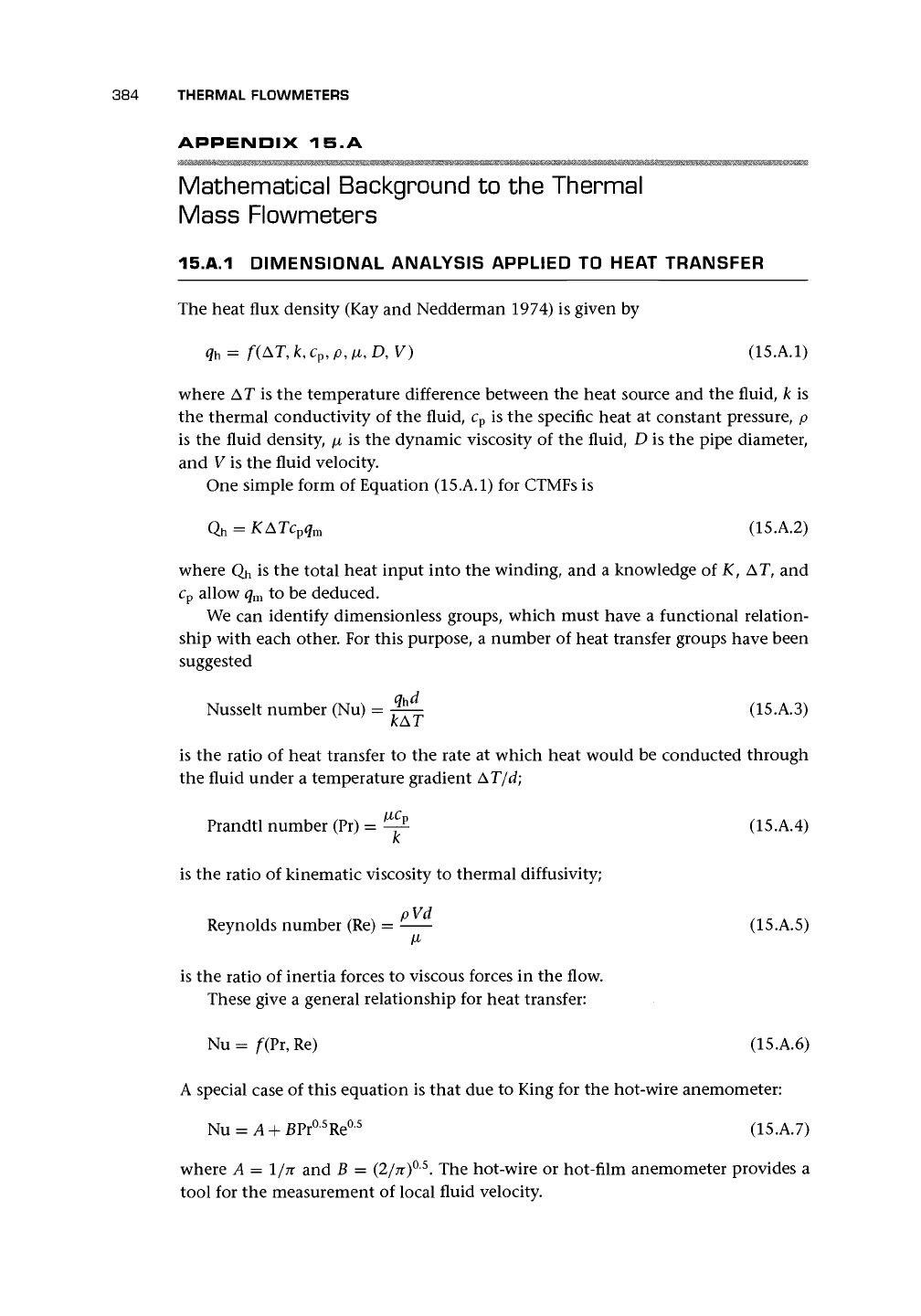
15.A.1 DIMENSIONAL ANALYSIS APPLIED TO HEAT TRANSFER
The heat flux density (Kay and Nedderman 1974) is given by
q
h
= f(AT, k, c
p
, p, ti, D, V) (15.A.1)
where AT is the temperature difference between the heat source and the fluid, k is
the thermal conductivity of the fluid, c
p
is the specific heat at constant pressure, p
is the fluid density,
\±
is the dynamic viscosity of the fluid, D is the pipe diameter,
and V is the fluid velocity.
One simple form of Equation (15.A.1) for CTMFs is
Q
h
= KATc
p
q
m
(15.A.2)
where Qh is the total heat input into the winding, and a knowledge of K, AT, and
c
p
allow q
m
to be deduced.
We can identify dimensionless groups, which must have a functional relation-
ship with each other. For this purpose, a number of heat transfer groups have been
suggested
Nusselt number (Nu) = ^- (15.A.3)
kAT
is the ratio of heat transfer to the rate at which heat would be conducted through
the fluid under a temperature gradient AT/d;
Prandtl number (Pr) = ^ (15.A.4)
K
is the ratio of kinematic viscosity to thermal diffusivity;
Reynolds number (Re) = -— (15.A.5)
/X
is the ratio of inertia forces to viscous forces in the flow.
These give a general relationship for heat transfer:
Nu = f(Pr, Re) (15.A.6)
A special case of this equation is that due to King for the hot-wire anemometer:
Nu = A + EPr°
5
Re°
5
(15.A.7)
where A = 1/n and B = (2/TT)
0
-
5
. The hot-wire or hot-film anemometer provides a
tool for the measurement of local fluid velocity.
15.A.2 BASIC THEORY OF ITMFS 385
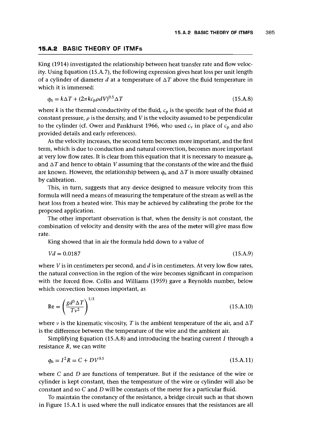
15.A.2 BASIC THEORY OF ITMFs
King (1914) investigated the relationship between heat transfer rate and flow veloc-
ity. Using Equation (15.A.7), the following expression gives heat loss per unit length
of a cylinder of diameter d at a temperature of AT above the fluid temperature in
which it is immersed:
q
h
= kAT+(27tkc
v
pdV)°-
5
AT (15.A.8)
where k is the thermal conductivity of the fluid, c
v
is the specific heat of the fluid at
constant pressure, p is the density, and V
is
the velocity assumed to be perpendicular
to the cylinder (cf. Ower and Pankhurst 1966, who used c
v
in place of c
p
and also
provided details and early references).
As the velocity increases, the second term becomes more important, and the first
term, which is due to conduction and natural convection, becomes more important
at very low flow rates. It is clear from this equation that it is necessary to measure
q^
and AT and hence to obtain V assuming that the constants of the wire and the fluid
are known. However, the relationship between q^ and AT is more usually obtained
by calibration.
This,
in turn, suggests that any device designed to measure velocity from this
formula will need a means of measuring the temperature of the stream as well as the
heat loss from a heated wire. This may be achieved by calibrating the probe for the
proposed application.
The other important observation is that, when the density is not constant, the
combination of velocity and density with the area of the meter will give mass flow
rate.
King showed that in air the formula held down to a value of
Vd = 0.0187 (15.A.9)
where V is in centimeters per second, and d is in centimeters. At very low flow rates,
the natural convection in the region of the wire becomes significant in comparison
with the forced flow. Collis and Williams (1959) gave a Reynolds number, below
which convection becomes important, as
3
U5.A.H,,
where v is the kinematic viscosity, T is the ambient temperature of the air, and AT
is the difference between the temperature of the wire and the ambient air.
Simplifying Equation (15.A.8) and introducing the heating current I through a
resistance R, we can write
q
h
= I
2
R = C +
DV
0S
(15.A.11)
where C and D are functions of temperature. But if the resistance of the wire or
cylinder is kept constant, then the temperature of the wire or cylinder will also be
constant and so C and D will be constants of the meter for a particular fluid.
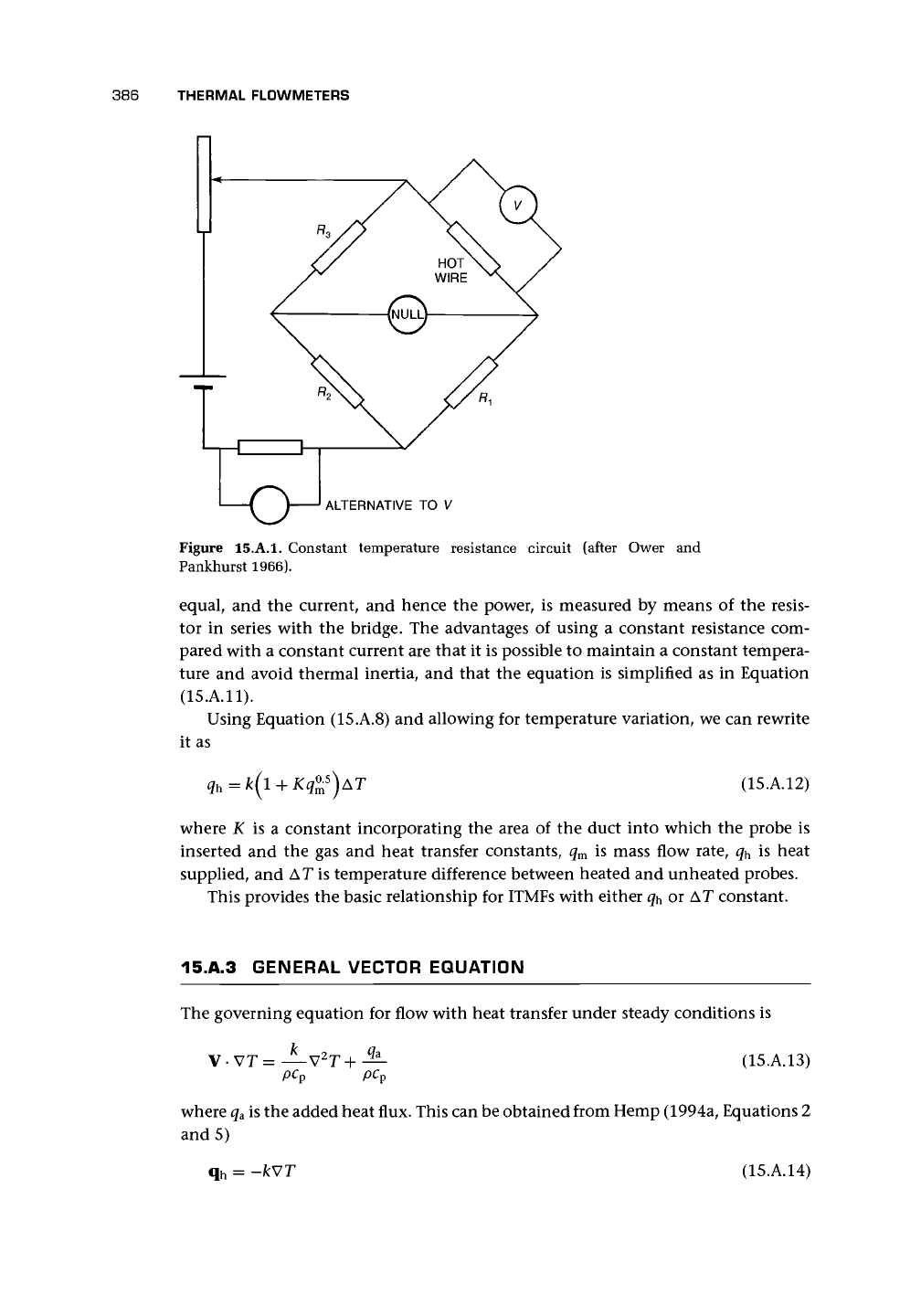
To maintain the constancy of the resistance, a bridge circuit such as that shown
in Figure 15.A.I is used where the null indicator ensures that the resistances are all
386
THERMAL FLOWMETERS
ALTERNATIVE TO V
Figure 15.A.I. Constant temperature resistance circuit (after Ower and
Pankhurst 1966).
equal, and the current, and hence the power, is measured by means of the resis-
tor in series with the bridge. The advantages of using a constant resistance com-
pared with a constant current are that it is possible to maintain a constant tempera-
ture and avoid thermal inertia, and that the equation is simplified as in Equation
(15.A.11).
Using Equation (15.A.8) and allowing for temperature variation, we can rewrite
it as
(15.A.12)
where K is a constant incorporating the area of the duct into which the probe is
inserted and the gas and heat transfer constants, q
m
is mass flow rate, q
h
is heat
supplied, and AT is temperature difference between heated and unheated probes.
This provides the basic relationship for ITMFs with either ^ or AT constant.
15.A.3 GENERAL VECTOR EQUATION
The governing equation for flow with heat transfer under steady conditions is
k
V-VT=
pc
p
pc
v
(15.A.13)
where
q
a
is the added heat flux. This can be obtained from Hemp (1994a, Equations 2
and 5)
q
h
= -kWT (15.A.14)