Baker R.C. Flow Measurement Handbook: Industrial Designs, Operating Principles, Performance, and Applications
Подождите немного. Документ загружается.

15.A.3 GENERAL VECTOR EQUATION 387
and
(15.A.15)
with the addition of the final term, which relates to the local heat addition. If all
heat is added across boundaries with the flow, then the last term disappears. Hemp
uses Equations (15.A.14) and (15.A.15) to develop his weight function theory for
thermal diffusion flowmeters. This is an elegant theory, and the interested reader is
encouraged to refer to Hemp's papers. However, as he comments, the work at present
is probably mainly of theoretical interest.
We can write Equation
(15.A.
13)
for flow in a two-dimensional channel as
,
=
(
dz pc
v
\dx
2
dz
2
pc
v
(15.A.16)
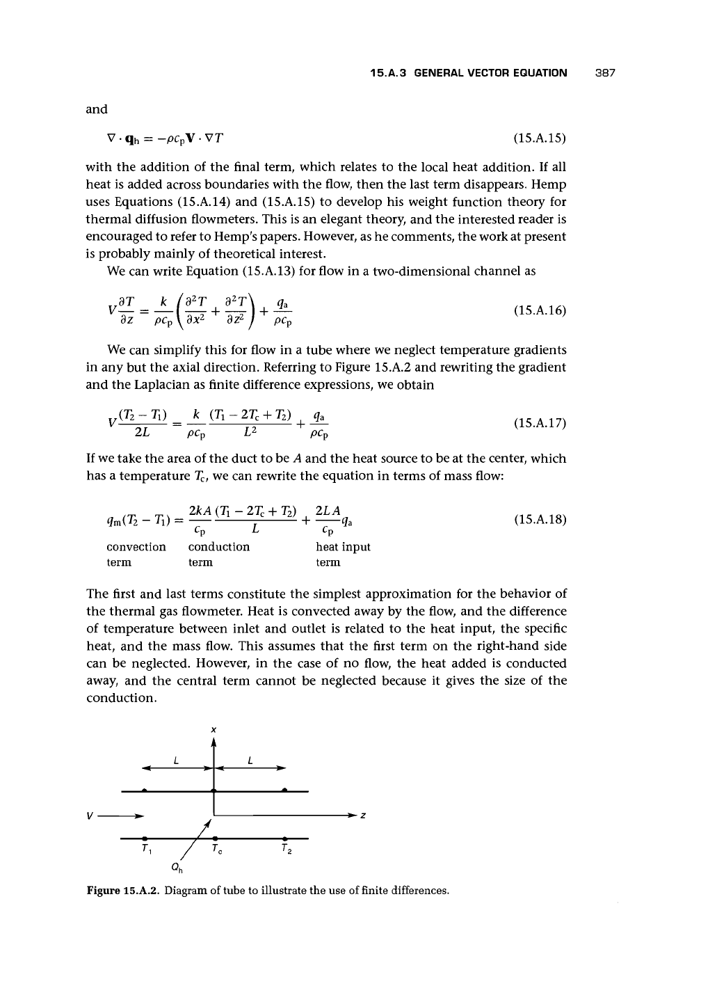
We can simplify this for flow in a tube where we neglect temperature gradients
in any but the axial direction. Referring to Figure 15.A.2 and rewriting the gradient
and the Laplacian as finite difference expressions, we obtain
v~
2L
L
2
(15.A.17)
If we take the area of the duct to be A and the heat source to be at the center, which
has a temperature T
c
, we can rewrite the equation in terms of mass flow:
convection
term
2kA (Ti - 2T
C
-
conduction
term
T
2
) 2LA
+ -—^a
(15.A.18)
heat input
term
The first and last terms constitute the simplest approximation for the behavior of
the thermal gas flowmeter. Heat is convected away by the flow, and the difference
of temperature between inlet and outlet is related to the heat input, the specific
heat, and the mass flow. This assumes that the first term on the right-hand side
can be neglected. However, in the case of no flow, the heat added is conducted
away, and the central term cannot be neglected because it gives the size of the
conduction.
L L
7",
Figure 15.A.2. Diagram of tube to illustrate the use of finite differences.
388
THERMAL FLOWMETERS
15.A.4 HASTINGS FLOWMETER THEORY
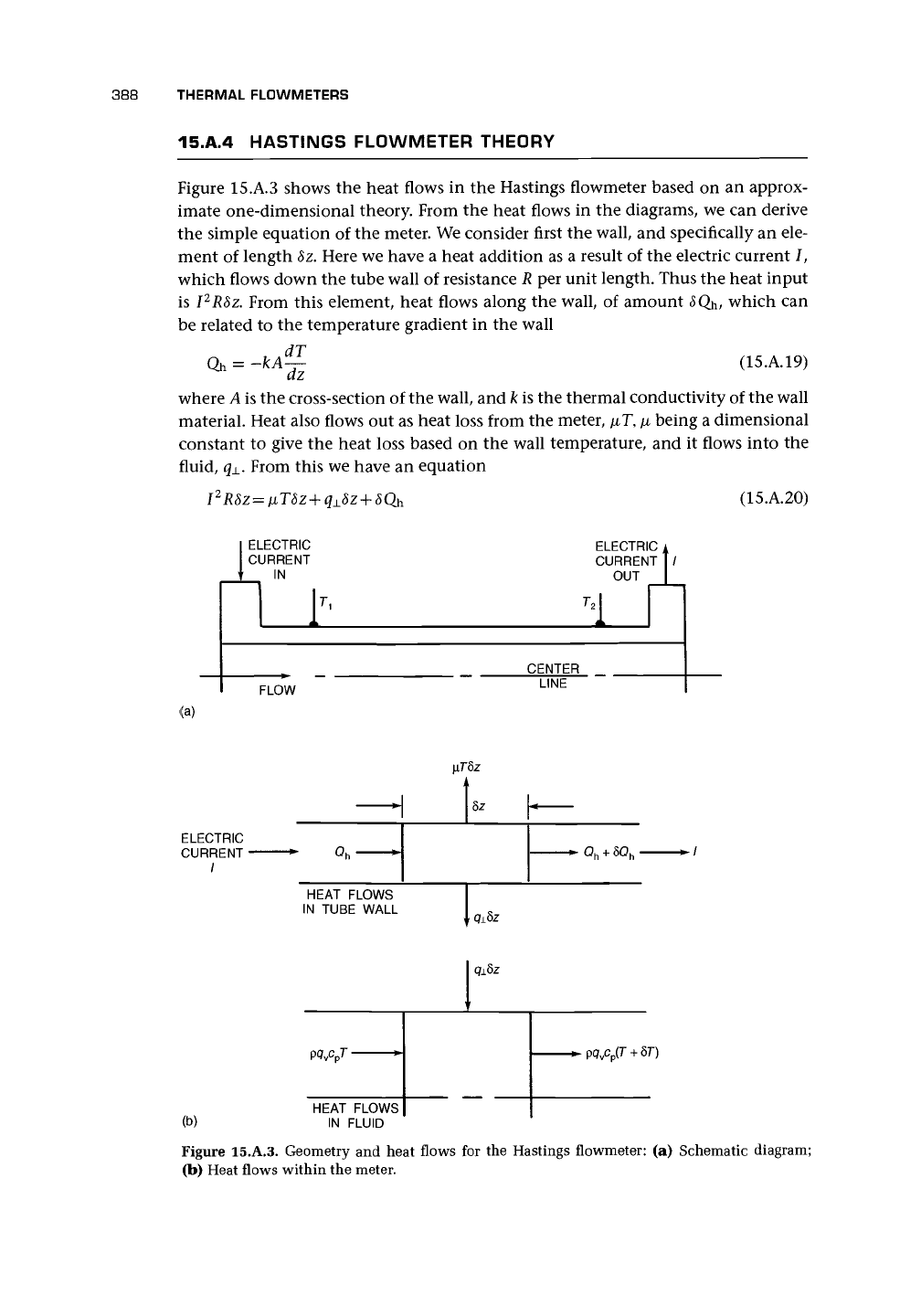
Figure 15.A.3 shows the heat flows in the Hastings flowmeter based on an approx-
imate one-dimensional theory. From the heat flows in the diagrams, we can derive
the simple equation of the meter. We consider first the wall, and specifically an ele-
ment of length 8z. Here we have a heat addition as a result of the electric current /,
which flows down the tube wall of resistance R per unit length. Thus the heat input
is I
2
R8z. From this element, heat flows along the wall, of amount <5Qh, which can
be related to the temperature gradient in the wall
Qh = -kA^- (15.A.19)
where A is the cross-section of the wall, and k is the thermal conductivity of the wall
material. Heat also flows out as heat loss from the meter, fiT,
[i
being a dimensional
constant to give the heat loss based on the wall temperature, and it flows into the
fluid, q±. From this we have an equation
(15.A.20)
ELECTRIC
CURRENT
IN
ELECTRIC
,
CURRENT
| /
OUT
T
±
CENTER
FLOW
LINE
\iThz
I
ELECTRIC
CURRENT•
HEAT FLOWS
IN TUBE WALL
9±5z
(b)
P
Q
v
c
p
7
HEAT FLOWS
IN FLUID
Figure 15.A.3. Geometry and heat flows for the Hastings flowmeter: (a) Schematic diagram;
(b) Heat flows within the meter.
15.A.5 WEIGHT VECTOR THEORY FOR THERMAL FLOWMETERS 389
q
L
8z then flows into the fluid, which is assumed to be at approximately the same
temperature as the wall at each point along its length. This heat causes a rise in the
temperature of the fluid. The rate of heat addition q
±
8z is equal to the product of
the temperature rise of the fluid, the specific heat of the fluid at constant pressure,
and the mass flow rate. Thus we can write
or
Finally, we can combine Equations (15.A.20) and (15.A.21) and use Equation
(15.A.19) to eliminate Qh
or
q
±
8z =
q± =
P<
pq
v
qvC
p
c
v
8T
dT
~dz
^ ^ fiT + IR = 0 (15.A.22)
dz
l
dz
This equation is quoted by Hemp (1995a), and he also quotes a solution due to
Blackett and Henry (1930), which for low flow rates can be written in a linear
form
T
2
-Ti=
Kq
v
(15.A.23)
Hemp suggests that the nonlinear complete solution is probably invalid outside
the linear range due to the assumptions about uniform temperature across any cross-
section of the flowmeter. For other solutions and more details, the reader is referred
to Hemp (1994a, 1995a), Blackett and Henry (1930), Komiya et al. (1988), Brown
and Kronberger (1947), and Widmer et al. (1982).
15.A.5 WEIGHT VECTOR THEORY FOR THERMAL FLOWMETERS
Hemp (1994a, 1995a) presented an extension of the weight vector theory to thermal
flowmeters. Again the ideal weight vector must satisfy
V x W = 0 (15.A.24)
For a typical thermal diffusion flowmeter, the signal
T
B
- T
c
=
f\-Wdv
(15.A.25)
and the weight vector is given by
W = pc
p
T
CB
VT
A
(15.A.26)
390 THERMAL FLOWMETERS
CAB
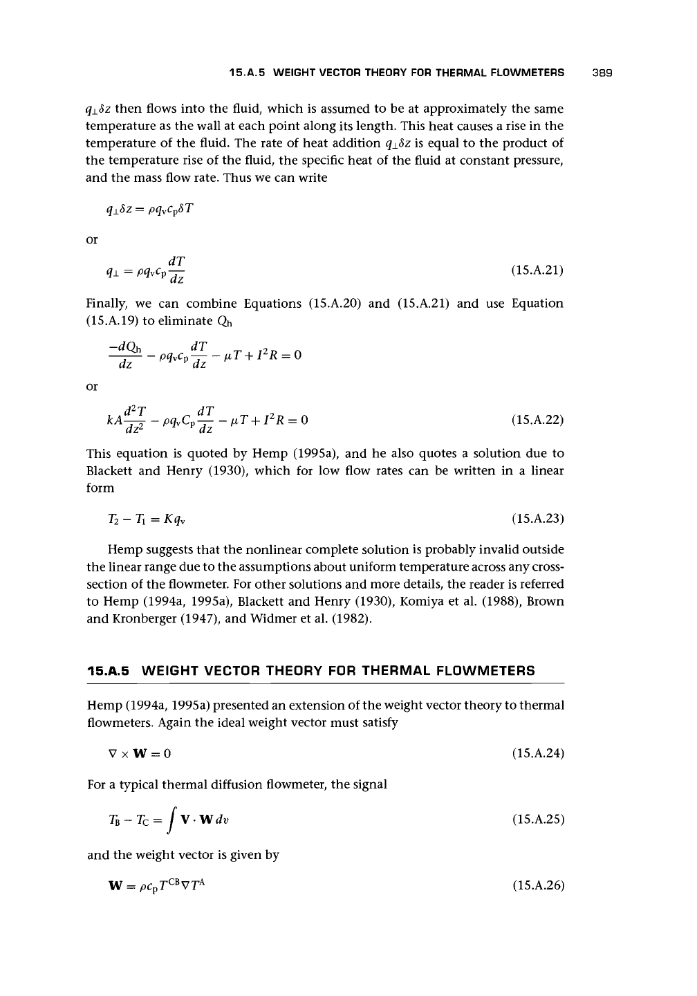
Figure 15.A.4. Diagram for Hemp (1994a) theory.
where T
A
is the temperature distribution resulting from unit heat flux injected into
A
(Figure 15.A.4), and T
CB
is the temperature distribution when unit heat flux enters
at C and leaves at B. It appears that the usefulness of Hemp's theory is limited at
present by the nature of the cases for which it is valid and the flow rates that are low
enough to ensure linear conditions.
CHAPTER
16
Angular Momentum Devices
16.1 INTRODUCTION
I am indebted to Medlock (1989) for notes on three early devices that attempt to use
change of angular momentum to obtain mass flow.
Katys (1964) used an electric synchronous motor with a special rotor supported
internally in the pipe and a stator outside the pipe. Fluid passed through vanes in the
rotor and acquired angular momentum. From the power used or the torque needed
to drive the rotor, it was claimed that the mass flow could be deduced.
According to Medlock, the Bendix meter "measures the torque required to impart
angular momentum to the liquid. One end of a calibrated spring is driven at a
constant speed and the other end is connected to a freely rotatable turbine. The
torsion developed in the spring is a measure of mass flow rate."
The twin rotor turbine meter (Potter 1959) attempted to measure mass flow by
means of two in-line turbine rotors of different blade angles, which are joined by
a torsion spring. Despite discussions with Medlock about this meter, I am not con-
vinced that this is a true mass flow meter and suggest that the valid derivative of the
Bendix meter is the fuel flow transmitter described later.
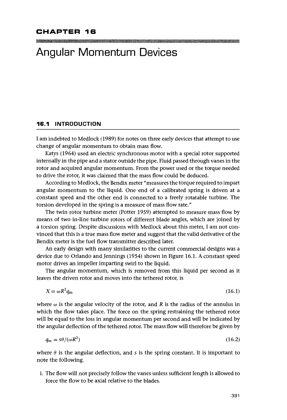
An early design with many similarities to the current commercial designs was a
device due to Orlando and Jennings (1954) shown in Figure
16.1.
A constant speed
motor drives an impeller imparting swirl to the liquid.
The angular momentum, which is removed from this liquid per second as it
leaves the driven rotor and moves into the tethered rotor, is
X
=
coR
2
q
m
(16.1)
where
co
is the angular velocity of the rotor, and R is the radius of the annulus in
which the flow takes place. The force on the spring restraining the tethered rotor
will be equal to the loss in angular momentum per second and will be indicated by
the angular deflection of the tethered rotor. The mass flow will therefore be given by
q
m
=
sO/(coR
2
)
(16.2)
where 0 is the angular deflection, and s is the spring constant. It is important to
note the following.
i. The flow will not precisely follow the vanes unless sufficient length is allowed to
force the flow to be axial relative to the blades.
391
392
ANGULAR MOMENTUM DEVICES
Constant
speed
motor
Section
through
impellers
Driven
impeller
Restrained
impeller
Figure 16.1. Orlando and Jennings device.
ii.
The flow profile in the annulus will modify the effective value of R.
iii.
The motor speed must be known.
16.2 THE FUEL FLOW TRANSMITTER
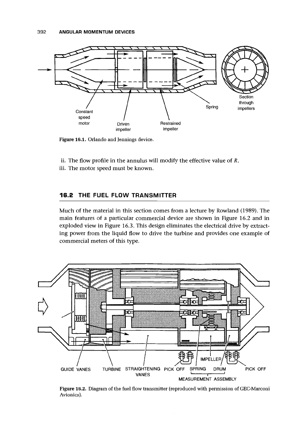
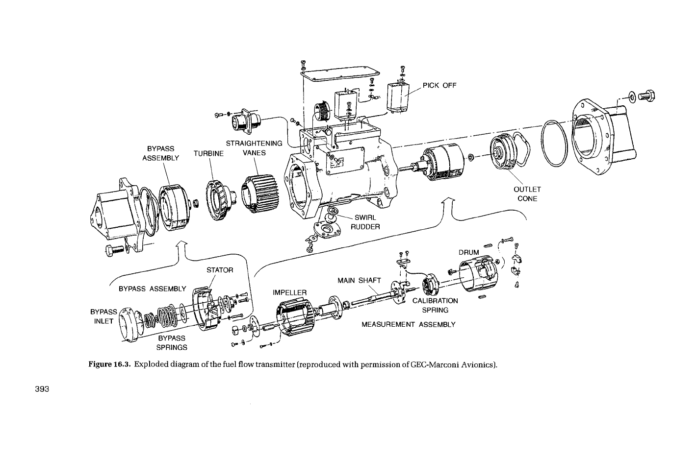
Much of the material in this section comes from a lecture by Rowland (1989). The
main features of a particular commercial device are shown in Figure 16.2 and in
exploded view in Figure 16.3. This design eliminates the electrical drive by extract-
ing power from the liquid flow to drive the turbine and provides one example of
commercial meters of this type.
GUIDE VANES TURBINE STRAIGHTENING PICK OFF SPRING DRUM
VANES ' 1
r
MEASUREMENT ASSEMBLY
PICK OFF
Figure 16.2. Diagram of the fuel flow transmitter (reproduced with permission of GEC-Marconi
Avionics).
MEASUREMENT ASSEMBLY
Figure
16.3.
Exploded diagram of the fuel flow transmitter (reproduced with permission of GEC-Marconi Avionics).
GO
CD
394 ANGULAR MOMENTUM DEVICES
16.2.1 QUALITATIVE DESCRIPTION
OF
OPERATION
As the flow enters the unit, a bypass assembly controls the amount of liquid passing
through the power turbine in order to avoid the assembly's running too fast or too
slow. The bypass mechanism consists of a spring-loaded bypass valve that contains
the speed of the unit to within the range 70-400 rpm. At the lowest flow rates, all
the liquid passes through the turbine, but as the flow rate increases, the build-up of
pressure across the turbine progressively opens the valve and allows an increasing
portion of the total liquid flow to bypass the turbine.
Depending on the opening of the bypass valve, a proportion of the flow passes
through a stator with guide vanes that create swirl in the flow. The flow then enters
the power turbine, which drives a shaft with the measurement assembly on the other
end. However, having extracted power from the flow in this way, it is essential that
the remaining swirl after the power turbine is completely removed from the liquid.
After the turbine and bypass valve, therefore, the flows combine to pass through
the straightening vanes, before passing into the driven measurement assembly. The
meter proper then follows and in this particular design, unlike the example described
earlier, measures the torque needed to impart the angular momentum to the liquid.
Within the rotating measurement assembly, a tethered impeller imparts to the liq-
uid the angular momentum. The ratio of blade length to mean space between the
impeller vanes is 8:1. Clearances are kept to a minimum to reduce leakage, and the
meter is insensitive to installation attitude.
In the process, the impeller experiences a torque that causes the restraining spring
made of NiSpan-C902, a material whose change of stiffness with temperature can
be adjusted by heat treatment, to tighten. To avoid overtightening the spring, the
bypass control of speed also reduces the necessary deflection of the spring. This can
be seen from the fact that, without the bypass, the angular velocity would be approx-
imately proportional to the mass flow rate and so the torque would be proportional
to the square of the angular velocity. By allowing some of the fluid to bypass the
drive turbine, the angular velocity is reduced, and the speed need not rise in propor-
tion to the mass flow rate. The relationship between flow rate and rotational speed
is shown in Figure 16.4.
The bearings are precision ball races. Friction errors and vibration errors can
result from spurious torques at the impeller bearings. The fuel acts as a lubricant and
must therefore be clean (filtered).
The deflection is measured by means of a pair of electromagnetic pickup coils
placed on the outside of the nonmagnetic meter body. A pair of small powerful
magnets displaced 180° apart are attached to the circumference of both drum and
impeller. Signals are therefore generated for each 180° of rotation of the assembly.
16.2.2 SIMPLE THEORY
We can obtain an expression for the mass flow rate. We write the spring constant
as s. The torque causes the impeller to be displaced by an angle 0 from the rest of
the measurement assembly. The displacement in the range 0-160° is measured by
recording the time of transit of a marker on the assembly drum and a marker on the
impeller. A knowledge of the time delay r and the angular velocity of the assembly
co
will then allow the angular displacement to be deduced. Maximum calibration
16.2 THE FUEL FLOW TRANSMITTER 395
1ST STAGE
SPRING
BOTH SPRINGS
OPERATING
FLOW RATE
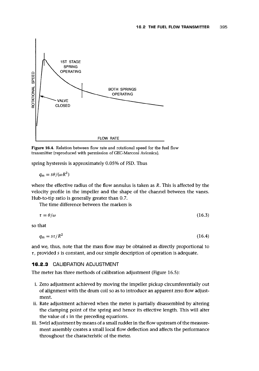
Figure 16.4. Relation between flow rate and rotational speed for the fuel flow
transmitter (reproduced with permission of GEC-Marconi Avionics).
spring hysteresis is approximately 0.05% of
FSD.
Thus
q
m
= sO/(coR
2
)
where the effective radius of the flow annulus is taken as R. This is affected by the
velocity profile in the impeller and the shape of the channel between the vanes.
Hub-to-tip ratio is generally greater than 0.7.
The time difference between the markers is
r =
0/Q)
(16.3)
so that
q
m
= sr/R
2
(16.4)
and we, thus, note that the mass flow may be obtained as directly proportional to
r, provided s is constant, and our simple description of operation is adequate.
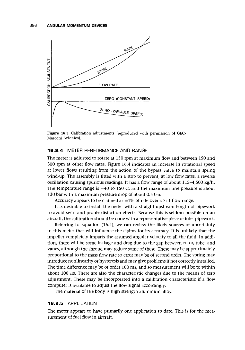
16.2.3 CALIBRATION ADJUSTMENT
The meter has three methods of calibration adjustment (Figure 16.5):
i. Zero adjustment achieved by moving the impeller pickup circumferentially out
of alignment with the drum coil so as to introduce an apparent zero flow adjust-
ment.
ii.
Rate adjustment achieved when the meter is partially disassembled by altering
the clamping point of the spring and hence its effective length. This will alter
the value of
5
in the preceding equations.
iii.
Swirl adjustment by means of
a
small rudder in the flow upstream of the measure-
ment assembly creates a small local flow deflection and affects the performance
throughout the characteristic of the meter.
396
ANGULAR MOMENTUM DEVICES
FLOW RATE
ZERO (CONSTANT SPEED)
Figure 16.5. Calibration adjustments (reproduced with permission of GEC-
Marconi Avionics).
16.2.4 METER PERFORMANCE AND RANGE
The meter is adjusted to rotate at 150 rpm at maximum flow and between 150 and
300 rpm at other flow rates. Figure 16.4 indicates an increase in rotational speed
at lower flows resulting from the action of the bypass valve to maintain spring
wind-up. The assembly is fitted with a stop to prevent, at low flow rates, a reverse
oscillation causing spurious readings. It has a flow range of about 115-4,500 kg/h.
The temperature range is -40 to 150°C, and the maximum line pressure is about
130 bar with a maximum pressure drop of about 0.5 bar.
Accuracy appears to be claimed as ±1% of rate over a 7:1 flow range.
It is desirable to install the meter with a straight upstream length of pipework
to avoid swirl and profile distortion effects. Because this is seldom possible on an
aircraft, the calibration should be done with a representative piece of inlet pipework.
Referring to Equation (16.4), we can review the likely sources of uncertainty
in this meter that will influence the claims for its accuracy. It is unlikely that the
impeller completely imparts the assumed angular velocity to all the fluid. In addi-
tion, there will be some leakage and drag due to the gap between rotor, tube, and
vanes,
although the shroud may reduce some of these. These may be approximately
proportional to the mass flow rate so error may be of second order. The spring may
introduce nonlinearity or hysteresis and may give problems if not correctly installed.
The time difference may be of order 100 ms, and so measurement will be to within
about 100 /xs. There are also the characteristic changes due to the means of zero
adjustment. These may be incorporated into a calibration characteristic if a flow
computer is available to adjust the flow signal accordingly.
The material of the body is high strength aluminum alloy.
16.2.5 APPLICATION
The meter appears to have primarily one application to date. This is for the mea-
surement of fuel flow in aircraft.