Baker R.C. Flow Measurement Handbook: Industrial Designs, Operating Principles, Performance, and Applications
Подождите немного. Документ загружается.

20.7 THE EFFECT OF INSTRUMENT ACCURACY ON PRODUCTION PROCESS 457
20.7.1 GENERAL EXAMPLES
OF THE
EFFECT
OF
PRECISION
OF
CONSTRUCTION
ON
INSTRUMENT QUALITY
Let us consider examples from various flowmeters.
a. Orifice plate. Variation in the sharpness of the leading edge will probably be due
to operator variation but may also be due to slight and random variation in the
quality of the material.
b.
Variable area flowmeter. Even though the glass tubes are made on a mandrel and
should have a well-controlled tolerance, the positioning of the scale will deter-
mine the accuracy, and as the device is essentially nonlinear, it will determine the
shape of the characteristic. This variation in positioning may be an unavoidable
consequence of the process and, being random, may produce a higher quality
instrument from time to time.
c. Positive displacement flowmeter. Variation of the clearance between the rotors
and the stator will cause a change in performance. This probably has more to do
with wear of the manufacturing process than a random effect.
d. Electromagnetic flowmeter. The construction of the coil and its positioning rel-
ative to the flow tube and electrodes will affect the performance and, to some
extent, may be random.
e. Ultrasonic flowmeter. The placing of the transducer cavities and the resulting
position of the transducers will determine the accuracy of the meter for varying
flows.
f. Coriolis flowmeter. The positioning of the sensors on the sensor tube, together
with other masses, may cause harmonics resulting in dither and twist, and the
consequent imprecision in the measurement of time difference between the two
sensing points on the oscillating tube.
In developing a design and production program for a particular flowmeter, the
company should be clear about the relationship between the primary construction
variables and the resulting performance of the flowmeter. It should be possible to
develop a curve for the effect of the precision of positioning on the accuracy of the
flowmeter. Assuming a normal distribution for the occurrence of mispositioning and
a curve for the relation between mispositioning and the randomness of the signal,
the variation of the randomness will result.
20.7.2 THEORETICAL RELATIONSHIP BETWEEN UNCERTAINTY
IN
MANUFACTURE
AND
INSTRUMENT SIGNAL QUALITY
We can express the equation of a flowmeter so as to relate the ratio of mass flow to
flow signal, to the parameters that result from the theory of its design. Thus, as a
simple example,
qm/s
= pi x p
2
x p
3
x p
4
(20.1)
where q
m
is the mass flow rate,
5
is the flow signal from the meter, and pi,
p
2
,...
are
dimensional and other factors. A high quality flowmeter will perform to an uncer-
tainty of better than 1%. (We are here ignoring the more complicated relationship
that would be modeled computationally.) The values of the parameters, pi, etc., will

458 SOME REFLECTIONS ON FLOWMETER MANUFACTURE, PRODUCTION, AND MARKETS
be affected by flow, installation, temperature, etc., and by manufacture. In general,
we may, therefore, write
q
m
/s= f(pi,p2,p3,p4) (20.2)
or
q
m
/s = /"(design, flow, installation, operating parameters, materials,
component precision, manufacturing accuracy,
quality of electronics) (20.3)
Assuming a constant design, flow, and installation and a design that minimizes
the effect of operating parameters, this simplifies to
q
m
/s = /""(materials consistency, component precision, manufacturing
accuracy, electronics quality) (20.4)
Small variations in manufacture can be related to small variation in performance
by
where me is used as the symbol for material consistency, cp for component preci-
sion, ma for manufacturing accuracy, and eq for electronics quality. Thus, if we can
obtain the partial derivative of mass flow/flow signal to, say, materials consistency,
we can decide for a certain quality of raw material whether the variation 8 me will
be acceptable or not in its effect on 8{q
m
/s). It is unlikely that we could work with
such general categories as materials consistency, and we will probably need to go to
detailed descriptions of the components such as tube dimensions, elastic modulus,
etc.
Similar equations will determine cost and life:
C =
——T-
= /"(materials consistency, component precision, manufacturing
accuracy, electronics quality) (20.6)
This cost equation has similarities to the total factor productivity. In this, we are
relating overall cost per unit at output to the input cost of individual components
per unit. In the total factor productivity, the object appeurs to be to relate product
output to material and process input. Again we can obtain the sensitivity of the total
cost to variation in the cost of individual components by obtaining the differential
form
8C =
8mc H
8cp
H 8ma H
8eq
(20.7)
dmc
dep dma deq
We can now weigh up the cost benefits of reducing material consistency from
Equation (20.7) against the loss of performance from Equation (20.5).
20.7 THE EFFECT OF INSTRUMENT ACCURACY ON PRODUCTION PROCESS 459
We may also be able to write an equation for reliability of the finished product
including time to failure.
So we could use a perturbation analysis or a parametric study using random
behavior of variables. Slack et al. (1995) suggested that there are various places in
which the use of graphical plots is recommended, both to track the change of a
variable with time and also to see if there is a link between two variables. If we
can measure the variation of the partial derivatives, we should have a prediction of
possible performance change in the future.
20.7.3 EXAMPLES OF UNCERTAINTY IN MANUFACTURE LEADING
TO INSTRUMENT SIGNAL RANDOMNESS
Case 1: Ultrasonic Flowmeter
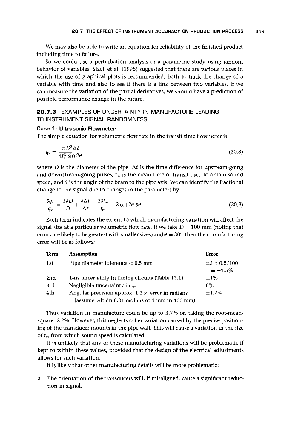
The simple equation for volumetric flow rate in the transit time flowmeter is
where D is the diameter of the pipe, At is the time difference for upstream-going
and downstream-going pulses, t
m
is the mean time of transit used to obtain sound
speed, and 9 is the angle of the beam to the pipe axis. We can identify the fractional
change to the signal due to changes in the parameters by
q
v
D At t
m
Each term indicates the extent to which manufacturing variation will affect the
signal size at a particular volumetric flow rate. If we take D = 100 mm (noting that
errors are likely to be greatest with smaller sizes) and
6
= 30°, then the manufacturing
error will be as follows:
Term Assumption Error
1st Pipe diameter tolerance < 0.5 mm ±3 x 0.5/100
= ±1.5%
2nd 1-ns uncertainty in timing circuits (Table 13.1) ±1%
3rd Negligible uncertainty in t
m
0%
4th Angular precision approx. 1.2 x error in radians ±1.2%
(assume within 0.01 radians or 1 mm in 100 mm)
Thus variation in manufacture could be up to 3.7% or, taking the root-mean-
square, 2.2%. However, this neglects other variation caused by the precise position-
ing of the transducer mounts in the pipe wall. This will cause a variation in the size
of t
m
from which sound speed is calculated.
It is unlikely that any of these manufacturing variations will be problematic if
kept to within these values, provided that the design of the electrical adjustments
allows for such variation.
It is likely that other manufacturing details will be more problematic:
a. The orientation of the transducers will, if misaligned, cause a significant reduc-
tion in signal.
460 SOME REFLECTIONS ON FLOWMETER MANUFACTURE, PRODUCTION, AND MARKETS
b.
The matching of the transducers for frequency response will be important.
c. The mounting of the transducers to ensure constant forward transmission and
minimal backward transmission will be essential.
Even though the dimensional changes will alter the calibration, they should not
affect the final accuracy. However, (a) might result in the beam being swept out
of range of the receiving transducer, and (c) could result in secondary interfering
signals reaching the receiving transducer. In either
case,
the precision of manufacture
will have an effect on the ultimate value to which the ultrasonic flowmeter can be
calibrated.
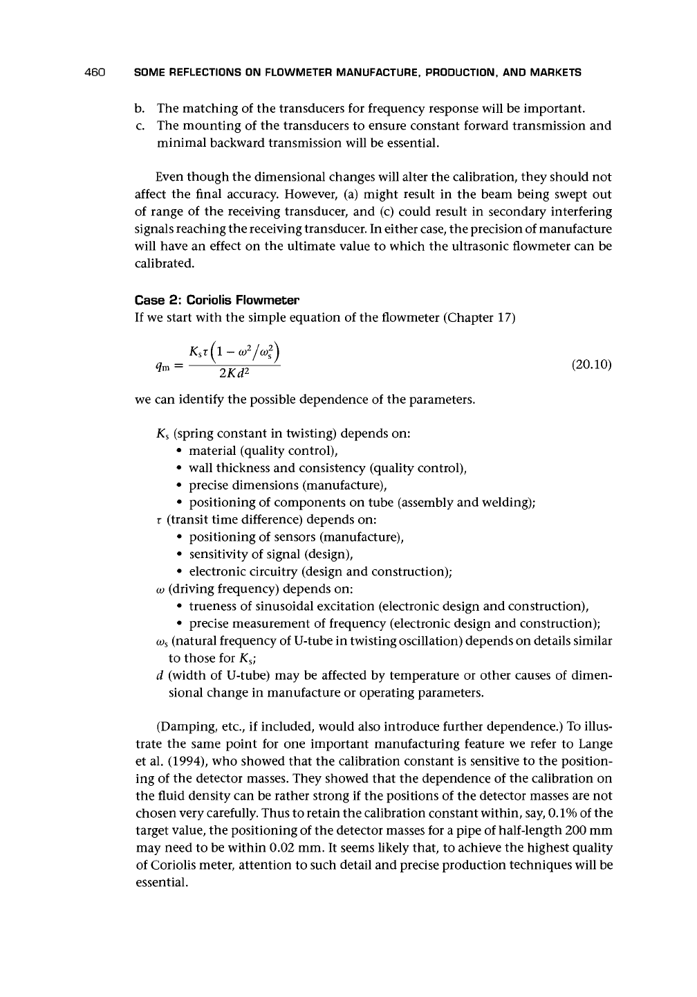
Case 2: Coriolis Flowmeter
If we start with the simple equation of the flowmeter (Chapter 17)
we can identify the possible dependence of the parameters.
K
s
(spring constant in twisting) depends on:
• material (quality control),
• wall thickness and consistency (quality control),
• precise dimensions (manufacture),
• positioning of components on tube (assembly and welding);
r (transit time difference) depends on:
• positioning of sensors (manufacture),
• sensitivity of signal (design),
• electronic circuitry (design and construction);
co
(driving frequency) depends on:
• trueness of sinusoidal excitation (electronic design and construction),
• precise measurement of frequency (electronic design and construction);
CD
S
(natural frequency of U-tube in twisting oscillation) depends on details similar
to those for K
s
;
d (width of U-tube) may be affected by temperature or other causes of dimen-
sional change in manufacture or operating parameters.
(Damping, etc., if included, would also introduce further dependence.) To illus-
trate the same point for one important manufacturing feature we refer to Lange
et al. (1994), who showed that the calibration constant is sensitive to the position-
ing of the detector masses. They showed that the dependence of the calibration on
the fluid density can be rather strong if the positions of the detector masses are not
chosen very carefully. Thus to retain the calibration constant within, say,
0.1%
of the
target value, the positioning of the detector masses for a pipe of half-length 200 mm
may need to be within 0.02 mm. It seems likely that, to achieve the highest quality
of Coriolis meter, attention to such detail and precise production techniques will be
essential.
20.9 ACTIONS FOR A TYPICAL FLOWMETER COMPANY 461
Thus we find that manufacturing precision in certain flowmeters can result in
two quite distinct effects:
a. Variation in the calibration constant but no loss in ultimate performance;
b.
Reduced quality of signal due to strength, secondary
signals,
or harmonics, which
limits the ultimate accuracy to which the meter can be calibrated.
20.8 CALIBRATION OF THE FINISHED FLOWMETERS
In most cases where the meters are for use on liquid,
a
gravimetric system as described
in Chapter 4 may be used. In other cases, it may be more convenient to use transfer
standards or pipe provers. The accuracy of the calibration facility is an essential part
of ensuring the quality and consistency of the product and should be built into the
logging system for the documentation of each unit produced.
One such calibration system using a critical nozzle test stand as part of the pro-
duction line for thermal mass flowmeters was described by Caron (1995). A second
rig tested the sensitivity of the meter to temperature. A third obtained the transfer
function of the flowmeters.
20.9 ACTIONS FOR A TYPICAL FLOWMETER COMPANY
Management should address some basic considerations:
a. For current products
• Are they preeminent technologically?
• Is the production system as efficient and flexible as possible?
• Has the market been mapped adequately, and do the products and the pro-
duction system respond adequately?
• How does the company's products compare with those of competitors?
Assuming that the questions in (a) have been answered to give an optimum market
sensitivity, the gap in market coverage should be clear.
b.
For new products
• What product should be added to the range that most complements existing
production?
• What other or competing manufacturers' products or designs are entering the
market?
• What is the critical time to market?
The existing industry competitors should be identified, and the weaknesses
of their products, which will be met by strengths in any new designs, should
be assessed. In some cases, the instrument type may be a substitute for a previ-
ous one. For instance, the orifice plate is likely to give way to other devices in
many industries, and the Coriolis will become more used in certain applications.
462 SOME REFLECTIONS ON FLOWMETER MANUFACTURE, PRODUCTION, AND MARKETS
The manufacturer must also address the following details of the production
process:
• Style of manufacture,
• Computer-based information and communication to control and expedite pro-
duct documentation, from material selection to final calibration and shipping,
• Buy in or make on site, and
• Quality control.
CHAPTER
21
Future Developments
21.1 MARKET DEVELOPMENTS
Lawton Smith (1994, cf. Kinghorn 1988) gave some overall figures (cf. Chapter 20)
for the flow measurement industry worldwide, which, with likely growth, suggest
that by the year 2000 it could be in excess of
US
$1 billion.
With this growing market in mind, we look at the new challenges that face the
flowmeter engineer, the current and future devices that may provide solutions, the
implications of information technology, and new production methods. The chapter
concludes with some suggestions for the way ahead, after a brief review of comments
that I made on future developments in an earlier book (Baker 1988/9).
21.2 EXISTING AND NEW FLOW MEASUREMENT CHALLENGES
Oil Exploration and Processing
The oil industry, dealing as it does with high value products, is likely to continue to
ask for more accurate meters capable of operating in adverse conditions, in multi-
phase flow, and in subsea installations.
Corneliussen (1991) of the Amoco Norway Oil Company described field experi-
ence with Hod metering, which was the first small unmanned production platform
in the Norwegian sector of the North Sea and started production in September 1990.
Gas and liquid were transported in a three-phase pipeline 13 km to another plat-
form from which Hod was operated. He described problems that appeared to have
stemmed from trapped air and gas in the pipeline and from a highly acidic well that
eventually caused the destruction of some of the meters. This is one example of the
increasingly difficult environment in which North Sea instrumentation must work.
Subsea metering of multicomponent flows is likely to become more common.
At the other end of the process, the measurement of fuel and flare gas for CO2-tax
is discussed by Raustein and Fosse (1991) of the Norwegian Petroleum Directorate.
Existing measurement uncertainty for fuel gas by either orifice plates or insertion
turbine meters is estimated to be
±2-5%.
By using insertion turbine meters, flow
sampling and thermal techniques, and ultrasonic flowmeters, overall accuracies for
flare gas metering are estimated to be ±5-10%. In the future, Raustein and Fosse
expected the quantities to be subject to taxation.
Between these two extremes of well extraction and gas discharge, there is the
detailed audit, monitoring, and control of each stage of the production process, and
463
464 FUTURE DEVELOPMENTS
the consequent requirement for accurate metering to cope with many and varied
fluids and installations.
Utilities
The last
10
years have seen major developments in the measurement of water and gas
for domestic purposes. The fluidic flowmeter described by Sanderson (1994) is an el-
egant solution to the need for a wide-ranging no-moving-part domestic water meter.
The ultrasonic gas meter is another example of the developments in utility flow
measurement in the last 10 years.
Kinghorn (1988), in the context of domestic water metering, mentioned remote
reading using mains-borne radio and telephone networks. Much development of
alternative communication systems has taken place in the past 10 years.
Mass
Although the Coriolis meter is proving to be a very accurate device for high value
liquids, the availability of a mass meter for gases is still a problem because all existing
meters, apart from the Coriolis, tend to be dependent on gas type. Ultrasonic and
thermal meters appear to lead the field at present.
Multiphase
Multiphase continues to be a challenge for the industry, which has not been solved
to an adequate extent. Of particular importance is the need to measure the flow of
moist gases and of steam in all its states.
Proving and Calibration
The compact prover and packages of sonic nozzles offer possibilities for site calibra-
tion.
Kinghorn (1996) discussed the measurement of fluid properties essential to the
flow measurement operation and the problems involved and suggested the use of
meters capable of compensating for changes in fluid properties. For example, gas
composition can cause a 0.28% discrepancy (Kinghorn 1988).
Local Velocity Measurement
A
whole area outside the scope of this book is local measurement of flow to aid the
design of fluid-handling equipment, both single and multiphase, ranging from ducts
and valves in single-phase flow systems to mixers and reactors in biotechnology
plant.
Research, Development, and Data Acquisition
A continuing theme for at least 30 years has been installation effects, and it is likely
to remain so to some extent, where flowmeters, which are sensitive to flow profile,
are in use. Computational methods of predicting the performance of flowmeters is
likely to become more accurate.
Kinghorn (1996) saw the possibility of reducing capital investment resulting from
flowmeter installation by developing meters less susceptible to installation:
• less affected by pulsation,
• less affected by upstream conditions,
21.3 NEW DEVICES AND METHODS 465
• capable of multiphase flow measurement, and
• unaffected by condensate
so that the flow conditioning becomes much less costly.
21.3 NEW DEVICES AND METHODS
21.3.1 DEVICES PROPOSED BUT NOT EXPLOITED
In this section, devices that, to my knowledge, have not been exploited are men-
tioned.
The many patents in this area demonstrate the activity in coming up with new
ideas.
Digests of these are available, for instance in the
Journal
of
Flow Measurement
and Instrumentation. No attempt has been made in this book to review and assess
their relative merits. I know of the devices that follow from my previous experience
or from recently published articles.
Brain et al. (1975) reported work on a gas ionization flowmeter in which the
ionization was due to a recessed and extended circumferential foil source of stron-
tium 90/yttrium 90 emitting beta radiation. The collection system removed ions in a
short axial length to create a striation in the ionized gas that was sensed by a drop in
current, and, hence, the transit time was obtained. The measurements were for 3-30
m/s,
and ±1% was claimed for most of the range. It was considered unsuitable for
gases with water vapor, oil mist, or solid particles, and, possibly, attitudes to nuclear
material make it unattractive.
Al-Rabeh and Hemp (1981) described a flowmeter that used the electrostatic
charges in insulating fluids. By setting a series of electrodes in the wall of the pipe,
each forming a ring, and by connecting these alternately, the passing of charge
created a sinusoidal signal, the frequency of which was proportional to the flow rate.
Nakano and Tanaka (1990) appear to have used a similar concept for oil hydraulic
pipelines.
Ellis et al. (1993) did further work on this type of meter to assess its value for
two-phase flows and claimed that it was possible to obtain the individual flow rates
of oil and gas in their rig. The meter consisted of two parts, one similar to that of
Al-Rabeh and Hemp (1981) and the second of two helical electrodes that obtained
the capacitance of the mixture and hence the void fraction. The void fraction mea-
surements appeared to be subject to an error of as much as 30%, although the total
flow rate error was within about ±7% rate (cf. Xingbin et al. 1996 and Yiming and
Haibo 1996).
Kolmakov and Korolev (1990) described an Alfven-wave flowmeter for those
interested in novel forms of flowmeter suitable for liquid metal flow measurement!
Flowmeters depending on nuclear magnetic resonance (NMR) have been sug-
gested over the last 20 years or so. To my knowledge, there is none on the market
at present. Gordgammer et al. (1990) showed that the NMR signal amplitude of
a gas-liquid mixture in diamagnetic fluids depended on the liquid content regard-
less of the physicochemical properties of the medium and conditions of flow. This
linearity
is
destroyed if paramagnetic centers are added to the fluid. Nuclear magnetic
resonance has also been used in liquid-gas flows to measure the mean velocity of the
liquid averaged over the liquid volume and also the average of the liquid fraction
466 FUTURE DEVELOPMENTS
(Kruger et al. 1996). The combination provided the mass flow of the liquid. In tests
using water as the liquid, they claimed to determine the mass flow to within ±5%.
Morgan and Aliyu (1993) described an ionic flowmeter for measuring small rates
of gas flow from 0.30 /ig/s to 0.20 mg/s. They claimed that the meter was best for
dry nonexplosive gases at a pressure of 4 x 10
2
Pa. The tube had an ion discharge at
the center. Ions were collected by ionization chambers up- and downstream of the
discharge, and under flowing conditions the currents were unequal. The internal
shape of the duct consisted of two chambers larger than the pipe joined by a small
duct within which the discharge occurred. The plot of mass flow against differential
current looked linear and promising. The meter did not directly measure mass flow
and required calibration. Each gas required separate calibration, and humidity could
also cause changes.
Joshi (1991) described a surface-acoustic-wave (SAW) flow sensor. The oscillation
frequency is temperature-dependent, and the element is heated above ambient, and
placed in the flowing gas so that convective cooling will make the frequency flow-
rate-dependent.
O'Rourke (1996) discussed the MTI gas meter, which uses an undulating wave-
shaped membrane that essentially forms traveling compartments of a positive dis-
placement sort and appears to give good performance. It is an interesting new con-
cept that may well have wider application (cf. Chapter 9).
A rather different aspect of domestic gas metering is the frequency of sampling
necessary to achieve required accuracy (Braathen 1996). Braathen claimed that sam-
pling every 16 seconds (a conservative figure as 32 seconds may be enough) or less
gave total gas passed to better than
0.1%
and that, by using random intervals, fraud
could be avoided. The advantage is gain in battery life.
Herzog and Roth (1990-1) described the principle of a differential pressure sen-
sor using optical fibers in a Mach-Zehnder interferometer configuration. They used
it to measure the pressure difference between two tubes across the pipe flow, the up-
stream one with a pressure tapping facing upstream and the downstream one with
a tapping facing downstream - a sort of averaging pitot tube with the upstream and
downstream tappings in two different tubes.
Strunck et al. (1996) described an intriguing use of four diode lasers - two beams
focused and intersecting in the boundary layer, and two intersecting on the axis
of the bell-mouth entry. The lasers heterodyned at a controlled frequency, and the
signals were picked up by four pin diodes on the other side, which gave velocity at
two points and, hence, the profile to ±0.15% for 500-5,000 m
3
/h.
Baker and Higham (1992) suggested that by using multiple bypasses in a
flowline, each of which contained a flowmeter, the flow in the main could be
measured. The interesting outcome of this type of approach is that the multiple
flowmeters can be mass produced, possibly using microtechniques, and if one fails,
it can be replaced without either ceasing to monitor the line flow or closing down
the line. A computer can monitor all flows and set an alarm when one needs to be
removed for replacement. Large lines could be monitored by small meters, with a
simple and robust contraction in the line to create the pressure drop to drive the
flow through the bypass meters.
Another variant of this would be to divide the flow in a large main into individual
paths through individual identical meters, each of which could be replaced without
closing down the flow. This could lead to a calibration facility in which a large flow