Baker R.C. Flow Measurement Handbook: Industrial Designs, Operating Principles, Performance, and Applications
Подождите немного. Документ загружается.

CHAPTER
IB
Probes for Local Velocity Measurement
in Liquids and Gases
18.1 INTRODUCTION
We resort to probes for flow measurement for three main reasons:
i. To provide a low cost method of flow monitoring;
ii.
To provide an in situ calibration;
iii.
To obtain fine detail of the flow in the pipe (velocity profile, swirl, and turbu-
lence).
For our present purposes, we shall not consider
(iii).
It
is
relevant to fluid mechan-
ics research, mainly uses hot-wire and laser doppler anemometers, and is, therefore,
outside the scope of this book. We will concentrate on work relating to bulk flow
measurement. In situ calibration techniques are covered in Chapter 4. In this chap-
ter we shall consider the various devices that have been used and are commercially
available either as a local flow monitor or as the probe for in situ calibration. How-
ever, before considering these, we need to understand what is being measured.
i. Ideally the probe measures the local velocity and obtains a representative value
of the mean velocity from the shape of the velocity profile. Alternatively, it may
measure the complete profile.
ii.
In practice the probe may be in error because:
• it was calibrated in an approximately uniform profile or on the pipe axis but
will need to measure velocity profiles that result in a significant variation of
velocity across the sensing head;
• it will alter the flow by its presence; and
• the flow pattern will continue to change as the probe head is inserted farther
and farther into the pipe and as it approaches the opposite side of the pipe.
In some cases, these flows may be analyzed theoretically, but in most cases one
would expect to calibrate the probe, and this calibration will be different at the
pipe axis and at the pipe wall.
iii.
The probe will reduce the flow area of the duct by its presence, and the area will
continually decrease as the probe is inserted farther. This blockage will need to
be allowed for. The blockage will also differ between incompressible and com-
pressible fluids.
Our object in using a probe is to obtain the best measure of the local flow rate
that can be obtained. We shall need to remember both the limitations of the probe
427
428 PROBES FOR LOCAL VELOCITY MEASUREMENT IN LIQUIDS AND GASES
and the uncertainty of the relationship between the reading and the mean velocity.
We also need to remember that, to deduce the mean flow rate in the duct, there is
uncertainty in the measurement of the cross-section of the pipe and the blockage
caused by the probe.
The variation on one probe, according to tests by the National Engineering Lab-
oratory in Scotland, suggested that blockage at the center for pipe sizes from 250 to
750 mm ranged between about ±5% and the change as the probe moves from the
center to the wall can be of order 10%.
For any new probe design, there is clearly a need for some careful work as to
a. what velocity the probe is measuring in an ideal uniform flow;
b.
how the signal will change in a real, nonuniform pipe flow, and when close to
the wall; and
c. how the flow in the duct will be altered by the probe and how the local probe
measurement would relate to the flow in the duct if no probe were present.
In Section 2.3 and, specifically, in Table 2.2, we noted that the velocity in a turbu-
lent flow at about the 0.76 radius point (0.24 of
a
radius in from the wall)
is
practically
equal to the mean flow in the pipe. So this suggests that the probe should be set at
this point. However, this may result in reduced precision due to the shape of the
flow profile in this region (b), the level of turbulence, and the proximity of the wall.
18.2 DIFFERENTIAL PRESSURE PROBES - PITOT PROBES
Using Equation (2.10), but introducing a factor k for nonideal conditions, we can
obtain the pressure rise when flow comes to rest in the entrance of a pitot tube
(Figure 18.1) as
, Stagnation
pressure
line
Static
tapping
Pitot tube
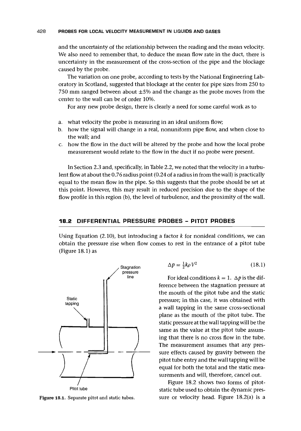
Figure
18.1.
Separate pitot and static tubes.
Ap=
\kpV
2
(18.1)
For ideal conditions k = 1. Ap is the dif-
ference between the stagnation pressure at
the mouth of the pitot tube and the static
pressure; in this case, it was obtained with
a wall tapping in the same cross-sectional
plane as the mouth of the pitot tube. The
static pressure at the wall tapping
will
be the
same as the value at the pitot tube assum-
ing that there is no cross flow in the tube.
The measurement assumes that any pres-
sure effects caused by gravity between the
pitot tube entry and the wall tapping will be
equal for both the total and the static mea-
surements and will, therefore, cancel out.
Figure 18.2 shows two forms of pitot-
static tube used to obtain the dynamic pres-
sure or velocity head. Figure 18.2(a) is a
18.2 DIFFERENTIAL PRESSURE PROBES - PITOT PROBES
429
FLOW
1 or 2 rings
STATIC
of 7 holes
TAPPINGS
(b)
/A
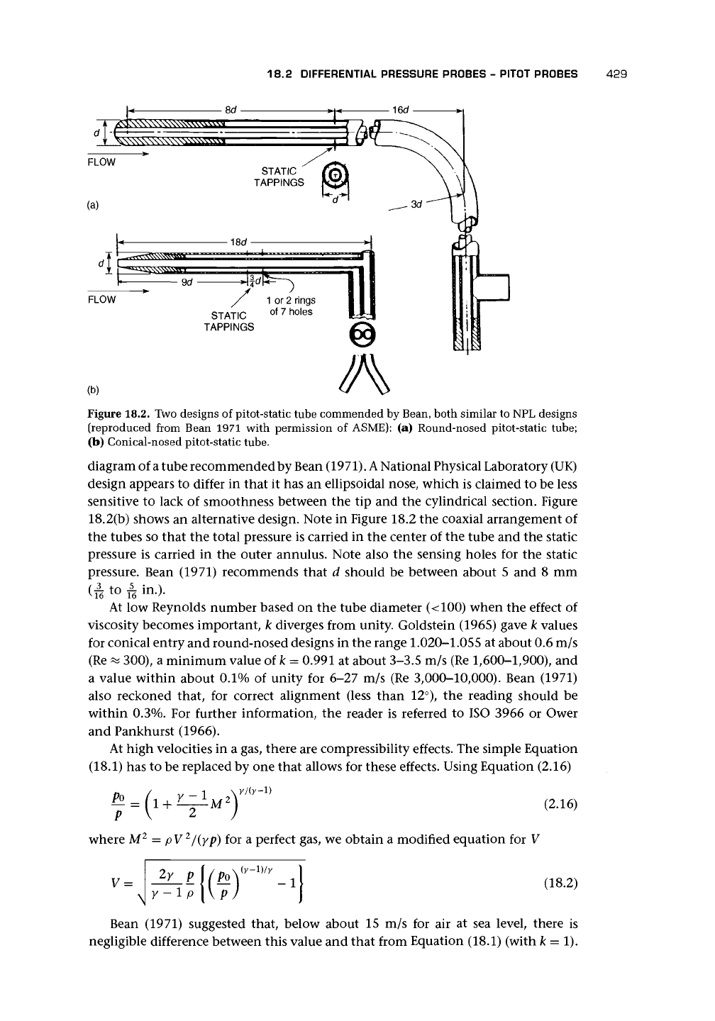
Figure 18.2. Two designs of pitot-static tube commended by Bean, both similar to NPL designs
(reproduced from Bean 1971 with permission of ASME): (a) Round-nosed pitot-static tube;
(b) Conical-nosed pitot-static tube.
diagram of
a
tube recommended by Bean (1971).
A
National Physical Laboratory (UK)
design appears to differ in that it has an ellipsoidal nose, which is claimed to be less
sensitive to lack of smoothness between the tip and the cylindrical section. Figure
18.2(b) shows an alternative design. Note in Figure 18.2 the coaxial arrangement of
the tubes so that the total pressure is carried in the center of the tube and the static
pressure is carried in the outer annulus. Note also the sensing holes for the static
pressure. Bean (1971) recommends that d should be between about 5 and 8 mm
(re to & in.)-
At low Reynolds number based on the tube diameter (<100) when the effect of
viscosity becomes important, k diverges from unity. Goldstein (1965) gave k values
for conical entry and round-nosed designs in the range
1.020-1.055
at about 0.6 m/s
(Re « 300), a minimum value of k = 0.991 at about 3-3.5 m/s (Re 1,600-1,900), and
a value within about 0.1% of unity for 6-27 m/s (Re 3,000-10,000). Bean (1971)
also reckoned that, for correct alignment (less than 12°), the reading should be
within 0.3%. For further information, the reader is referred to ISO 3966 or Ower
and Pankhurst (1966).
At high velocities in a gas, there are compressibility effects. The simple Equation
(18.1) has to be replaced by one that allows for these effects. Using Equation (2.16)
(2.16)
where M
2
= pV
2
/(yp) for a perfect gas, we obtain a modified equation for V
V =
\
2y
p\(Po\
y
-
1)/y
-\p \\p)
(18.2)
Bean (1971) suggested that, below about 15 m/s for air at sea level, there is
negligible difference between this value and that from Equation (18.1) (with k = 1).
430
PROBES FOR LOCAL VELOCITY MEASUREMENT IN LIQUIDS AND GASES
We can see this if we rewrite Equation (18.2) as
+
p)
If we then use the binomial theorem to expand the inner bracket, we obtain
V
2
=
2y p f
|
y-\ Ap
y - 1 p \ y p
(18.4)
assuming that we can neglect terms of order (Ap/p)
2
and greater. This reduces to
V
2
=
2Ap
(18.5)
In neglecting terms of order (Ap/p)
2
or greater powers, we have neglected terms of
order (\pV
2
/p)
2
or greater. If p = 1.3, V = 15 m/s, and p = 10
5
Pa (1 bar), then the
error resulting from ignoring \pV
2
/p is of order 0.15%, confirming Bean's value.
One major problem with the pi tot tube
is the effect of unsteady flow on its read-
ing, and because turbulence is very com-
mon in normal industrial flows, the pitot
tube will tend to read high (cf. Goldstein
1936).
MacMillan (1954) discussed the ef-
fects of low Reynolds number and noted
(MacMillan 1957) that in a shear flow there
was an apparent shift in the effective center
of the pitot tube of 0.1 Sd in the direction of
high velocity, where d is the outside diam-
eter of the pitot tube.
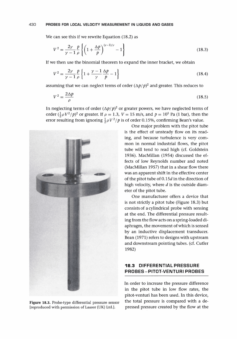
One manufacturer offers a device that
is not strictly a pitot tube (Figure 18.3) but
consists of
a
cylindrical probe with sensing
at the end. The differential pressure result-
ing from the flow acts on a spring-loaded di-
aphragm, the movement of which is sensed
by an inductive displacement transducer.
Bean (1971) refers to designs with upstream
and downstream pointing tubes, (cf. Cutler
1982)
Figure 18.3. Probe-type differential pressure sensor
[reproduced with permission of Laaser (UK)
Ltd.].
18.3 DIFFERENTIALPRESSURE
PROBES-PITOT-VENTURI PROBES
In order to increase the pressure difference
in the pitot tube in low flow rates, the
pitot-venturi has been used. In this device,
the total pressure is compared with a de-
pressed pressure created by the flow at the
18.5 INSERTION TURBINE METER
431
(a)
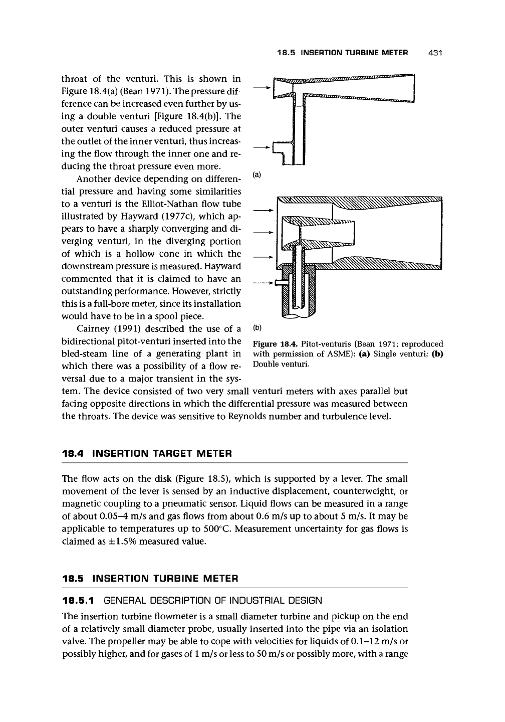
throat of the venturi. This is shown in
Figure 18.4(a) (Bean 1971). The pressure dif-
ference can be increased even further by us-
ing a double venturi [Figure 18.4(b)]. The
outer venturi causes a reduced pressure at
the outlet of the inner venturi, thus increas-
ing the flow through the inner one and re-
ducing the throat pressure even more.
Another device depending on differen-
tial pressure and having some similarities
to a venturi is the Elliot-Nathan flow tube
illustrated by Hayward (1977c), which ap-
pears to have a sharply converging and di-
verging venturi, in the diverging portion
of which is a hollow cone in which the
downstream pressure is measured. Hayward
commented that it is claimed to have an
outstanding performance. However, strictly
this is a full-bore meter, since its installation
would have to be in a spool piece.
Cairney (1991) described the use of a
bidirectional pitot-venturi inserted into the
bled-steam line of a generating plant in
which there was a possibility of a flow re-
versal due to a major transient in the sys-
tem. The device consisted of two very small venturi meters with axes parallel but
facing opposite directions in which the differential pressure was measured between
the throats. The device was sensitive to Reynolds number and turbulence level.
Figure 18.4. Pitot-Venturis (Bean 1971; reproduced
with permission of ASME): (a) Single venturi; (b)
Double venturi.
18.4 INSERTION TARGET METER
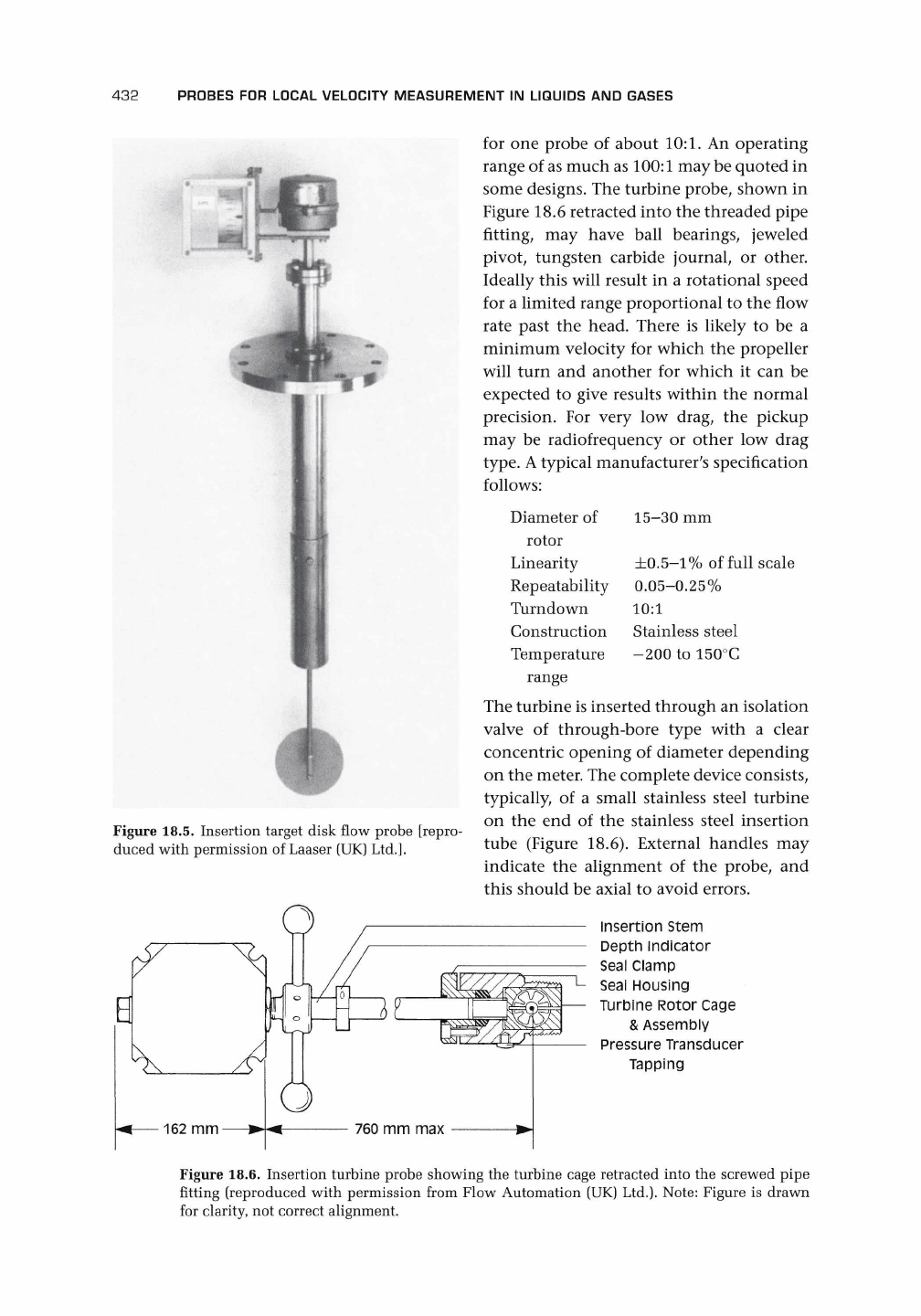
The flow acts on the disk (Figure 18.5), which is supported by a lever. The small
movement of the lever is sensed by an inductive displacement, counterweight, or
magnetic coupling to a pneumatic sensor. Liquid flows can be measured in a range
of about 0.05-4 m/s and gas flows from about 0.6 m/s up to about 5 m/s. It may be
applicable to temperatures up to 500°C. Measurement uncertainty for gas flows is
claimed as ±1.5% measured value.
18.5 INSERTION TURBINE METER
18.5.1 GENERAL DESCRIPTION OF INDUSTRIAL DESIGN
The insertion turbine flowmeter is a small diameter turbine and pickup on the end
of a relatively small diameter probe, usually inserted into the pipe via an isolation
valve. The propeller may be able to cope with velocities for liquids of 0.1-12 m/s or
possibly higher, and for gases of
1
m/s or less to 50 m/s or possibly more, with a range
432
PROBES
FOR
LOCAL VELOCITY MEASUREMENT
IN
LIQUIDS
AND
GASES
Figure 18.5. Insertion target disk flow probe [repro-
duced with permission
of
Laaser (UK)
Ltd.].
for
one
probe
of
about 10:1.
An
operating
range
of
as
much as 100:1 may be quoted
in
some designs. The turbine probe, shown
in
Figure 18.6 retracted into the threaded pipe
fitting,
may
have ball bearings, jeweled
pivot, tungsten carbide journal,
or
other.
Ideally this will result
in a
rotational speed
for
a
limited range proportional
to the
flow
rate past
the
head. There
is
likely
to be a
minimum velocity
for
which
the
propeller
will turn
and
another
for
which
it can be
expected
to
give results within
the
normal
precision.
For
very
low
drag,
the
pickup
may
be
radiofrequency
or
other
low
drag
type.
A
typical manufacturer's specification
follows:
15-30 mm
±0.5-1%
of full scale
0.05-0.25%
10:1
Stainless steel
-200 to 150°C
Diameter of
rotor
Linearity
Repeatability
Turndown
Construction
Temperature
range
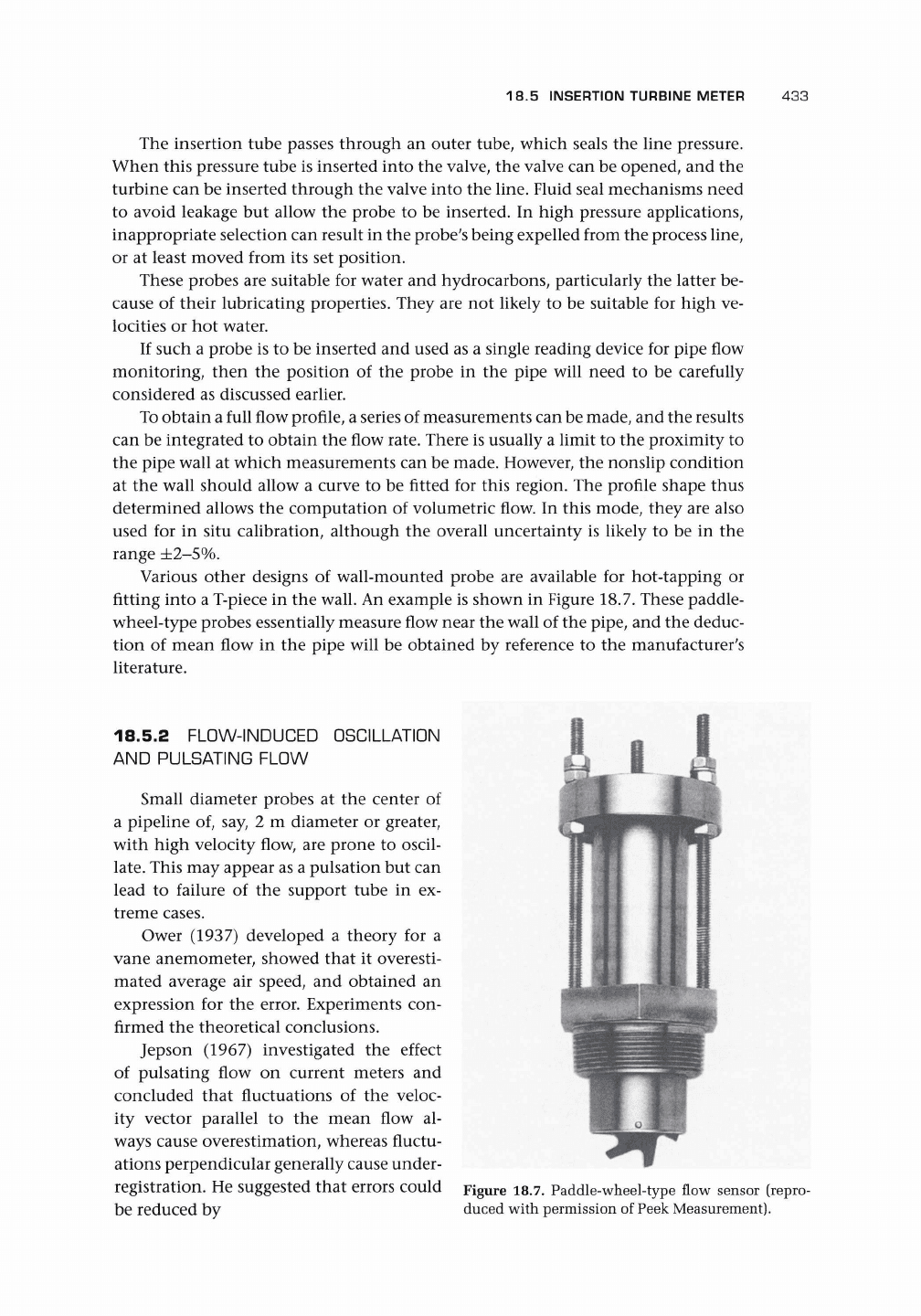
The turbine is inserted through
an
isolation
valve
of
through-bore type with
a
clear
concentric opening
of
diameter depending
on the meter. The complete device consists,
typically,
of a
small stainless steel turbine
on
the end of the
stainless steel insertion
tube (Figure 18.6). External handles
may
indicate
the
alignment
of the
probe,
and
this should
be
axial
to
avoid errors.
insertion Stem
Depth indicator
Seal Clamp
Seal Housing
Turbine Rotor Cage
& Assembly
Pressure Transducer
Tapping
Figure 18.6. Insertion turbine probe showing
the
turbine cage retracted into
the
screwed pipe
fitting (reproduced with permission from Flow Automation (UK) Ltd.). Note: Figure
is
drawn
for clarity,
not
correct alignment.
18.5 INSERTION TURBINE METER
433
The insertion tube passes through an outer tube, which seals the line pressure.
When this pressure tube is inserted into the valve, the valve can be opened, and the
turbine can be inserted through the valve into the line. Fluid seal mechanisms need
to avoid leakage but allow the probe to be inserted. In high pressure applications,
inappropriate selection can result in the probe's being expelled from the process line,
or at least moved from its set position.
These probes are suitable for water and hydrocarbons, particularly the latter be-
cause of their lubricating properties. They are not likely to be suitable for high ve-
locities or hot water.
If such a probe is to be inserted and used as a single reading device for pipe flow
monitoring, then the position of the probe in the pipe will need to be carefully
considered as discussed earlier.
To obtain a full flow profile, a series of measurements can be made, and the results
can be integrated to obtain the flow rate. There is usually a limit to the proximity to
the pipe wall at which measurements can be made. However, the nonslip condition
at the wall should allow a curve to be fitted for this region. The profile shape thus
determined allows the computation of volumetric flow. In this mode, they are also
used for in situ calibration, although the overall uncertainty is likely to be in the
range
±2-5%.
Various other designs of wall-mounted probe are available for hot-tapping or
fitting into a T-piece in the wall. An example is shown in Figure 18.7. These paddle-
wheel-type probes essentially measure flow near the wall of the pipe, and the deduc-
tion of mean flow in the pipe will be obtained by reference to the manufacturer's
literature.
18.5.2 FLOW-INDUCED OSCILLATION
AND PULSATING FLOW
Small diameter probes at the center of
a pipeline of, say, 2 m diameter or greater,
with high velocity flow, are prone to oscil-
late.
This may appear as a pulsation but can
lead to failure of the support tube in ex-
treme cases.
Ower (1937) developed a theory for a
vane anemometer, showed that it overesti-
mated average air speed, and obtained an
expression for the error. Experiments con-
firmed the theoretical conclusions.
Jepson (1967) investigated the effect
of pulsating flow on current meters and
concluded that fluctuations of the veloc-
ity vector parallel to the mean flow al-
ways cause overestimation, whereas fluctu-
ations perpendicular generally cause under-
registration. He suggested that errors could
be reduced by
Figure 18.7. Paddle-wheel-type flow sensor (repro-
duced with permission of Peek Measurement).
434
PROBES FOR LOCAL VELOCITY MEASUREMENT IN LIQUIDS AND GASES
a. using blades with a large aspect ratio,
b.
making the tip-to-tip diameter small to keep the blade thickness as small as
possible,
c. keeping the blade angle to a minimum, and
d. using low density material for the rotor.
Jepson's paper is a useful source of earlier references on current meters.
18.5.3 APPLICATIONS
Application of turbine probes to large diameter pipe flow measurement should be
undertaken with care, recognizing the need for an integration routine, the blockage
effect caused by the probe, the effect of wall on probe calibration, the errors in
measurement of pipe diameter, and the total uncertainty of final value of flow rate.
Turbine probes have been used in applications such as compressor efficiency and
surge control, pipeline leak detection, odorizers, samplers, and checking through-
put. Some have claimed that this device can be used for custody transfer to mea-
sure with high accuracy and reduce cost by avoiding the purchase, installation, and
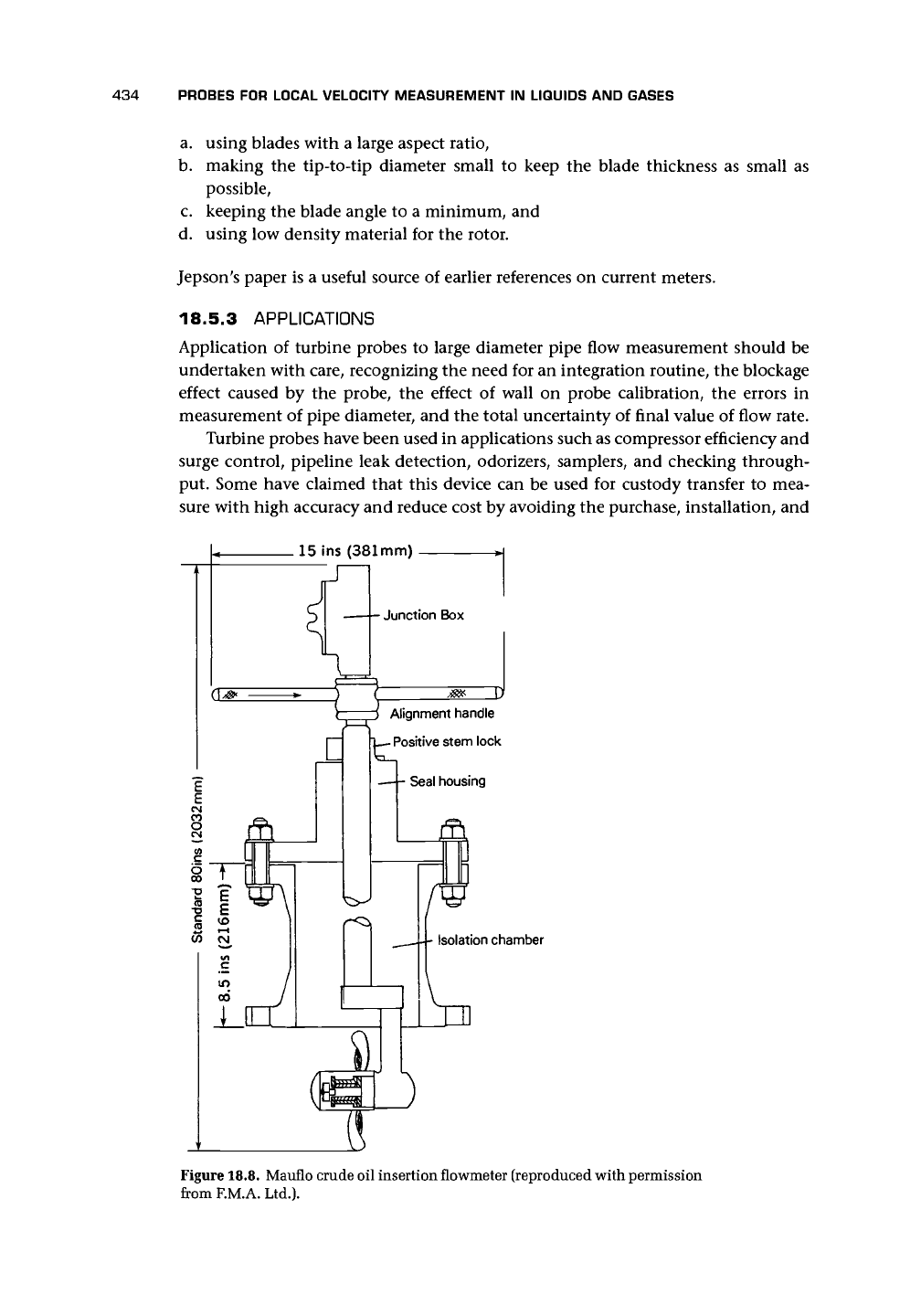
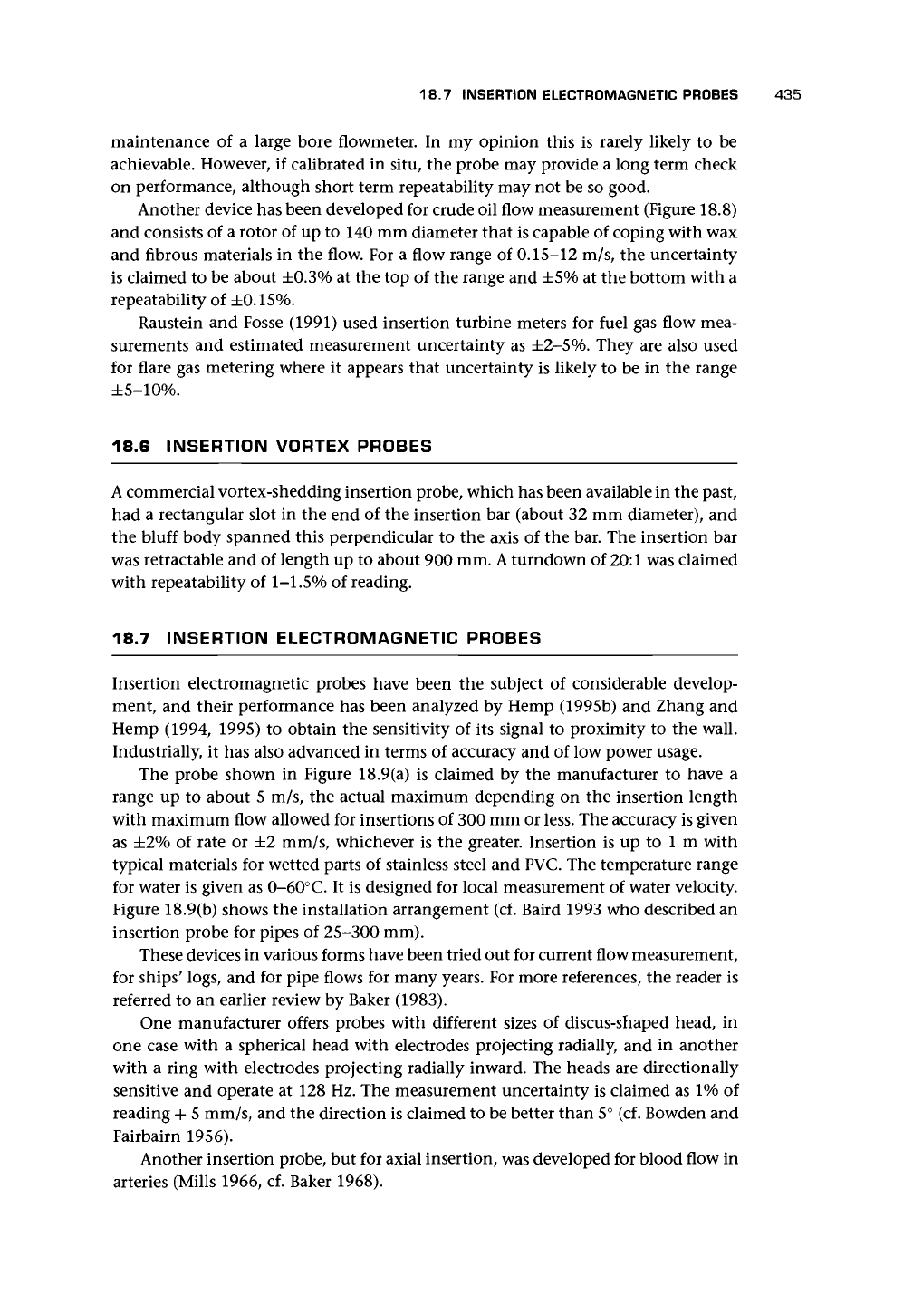
15 ins (381mm)
Junction Box
Alignment handle
-
Positive stem lock
Seal housing
Isolation chamber
Figure 18.8. Mauflo crude oil insertion flowmeter (reproduced with permission
from F.M.A. Ltd.).
18.7 INSERTION ELECTROMAGNETIC PROBES 435
maintenance of a large bore flowmeter. In my opinion this is rarely likely to be
achievable. However, if calibrated in situ, the probe may provide a long term check
on performance, although short term repeatability may not be so good.
Another device has been developed for crude oil flow measurement (Figure 18.8)
and consists of a rotor of up to 140 mm diameter that is capable of coping with wax
and fibrous materials in the flow. For a flow range of 0.15-12 m/s, the uncertainty
is claimed to be about ±0.3% at the top of the range and ±5% at the bottom with a
repeatability of ±0.15%.
Raustein and Fosse (1991) used insertion turbine meters for fuel gas flow mea-
surements and estimated measurement uncertainty as
±2-5%.
They are also used
for flare gas metering where it appears that uncertainty is likely to be in the range
±5-10%.
18.6 INSERTION VORTEX PROBES
A
commercial vortex-shedding insertion probe, which has been available in the past,
had a rectangular slot in the end of the insertion bar (about 32 mm diameter), and
the bluff body spanned this perpendicular to the axis of the bar. The insertion bar
was retractable and of length up to about 900 mm.
A
turndown of
20:1
was claimed
with repeatability of
1-1.5%
of reading.
18.7 INSERTION ELECTROMAGNETIC PROBES
Insertion electromagnetic probes have been the subject of considerable develop-
ment, and their performance has been analyzed by Hemp (1995b) and Zhang and
Hemp (1994, 1995) to obtain the sensitivity of its signal to proximity to the wall.
Industrially, it has also advanced in terms of accuracy and of low power usage.
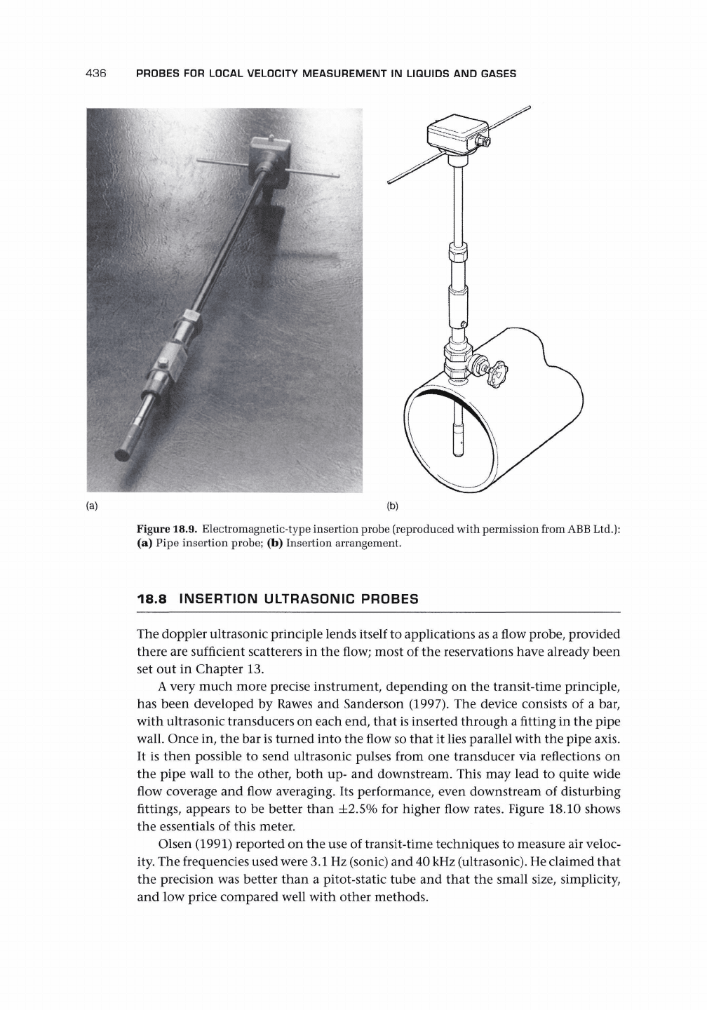
The probe shown in Figure 18.9(a) is claimed by the manufacturer to have a
range up to about 5 m/s, the actual maximum depending on the insertion length
with maximum flow allowed for insertions of 300 mm or less. The accuracy is given
as ±2% of rate or ±2 mm/s, whichever is the greater. Insertion is up to 1 m with
typical materials for wetted parts of stainless steel and PVC. The temperature range
for water is given as 0-60°C. It is designed for local measurement of water velocity.
Figure 18.9(b) shows the installation arrangement (cf. Baird 1993 who described an
insertion probe for pipes of 25-300 mm).
These devices in various forms have been tried out for current flow measurement,
for ships' logs, and for pipe flows for many years. For more references, the reader is
referred to an earlier review by Baker (1983).
One manufacturer offers probes with different sizes of discus-shaped head, in
one case with a spherical head with electrodes projecting radially, and in another
with a ring with electrodes projecting radially inward. The heads are directionally
sensitive and operate at 128 Hz. The measurement uncertainty is claimed as 1% of
reading + 5 mm/s, and the direction is claimed to be better than 5° (cf. Bowden and
Fairbairn 1956).
Another insertion probe, but for axial insertion, was developed for blood flow in
arteries (Mills 1966, cf. Baker 1968).
436
PROBES FOR LOCAL VELOCITY MEASUREMENT IN LIQUIDS AND GASES
(b)
Figure 18.9. Electromagnetic-type insertion probe (reproduced with permission from
ABB
Ltd.):
(a) Pipe insertion probe; (b) Insertion arrangement.
18.8 INSERTION ULTRASONIC PROBES
The doppler ultrasonic principle lends itself to applications as a flow probe, provided
there are sufficient scatterers in the flow; most of the reservations have already been
set out in Chapter 13.
A
very much more precise instrument, depending on the transit-time principle,
has been developed by Rawes and Sanderson (1997). The device consists of a bar,
with ultrasonic transducers on each end, that is inserted through a fitting in the pipe
wall. Once in, the bar is turned into the flow so that it lies parallel with the pipe axis.
It is then possible to send ultrasonic pulses from one transducer via reflections on
the pipe wall to the other, both up- and downstream. This may lead to quite wide
flow coverage and flow averaging. Its performance, even downstream of disturbing
fittings, appears to be better than ±2.5% for higher flow rates. Figure 18.10 shows
the essentials of this meter.
Olsen (1991) reported on the use of transit-time techniques to measure air veloc-
ity. The frequencies used were 3.1 Hz (sonic) and 40 kHz (ultrasonic). He claimed that
the precision was better than a pitot-static tube and that the small size, simplicity,
and low price compared well with other methods.