Balakumar Balachandran, Magrab E.B. Vibrations
Подождите немного. Документ загружается.


Comparing Eqs. (c), (e), and (f) to Eqs. (3.46), we find that the equivalent in-
ertia, the equivalent stiffness, and the equivalent damping properties of the
system are given by, respectively,
(g)
Noting that the only external force acting on the system is gravity load-
ing, and that this has already been taken into account, the governing equation
of motion is obtained from the last of Eqs. (3.47) as
(h)
Then, from the first of Eqs. (3.48) and (g), we find that
(i)
It is pointed out that k
e
can be negative, which affects the stability of the
system as discussed in Section 4.3. The equivalent stiffness k
e
is positive when
(j)
that is, when the net moment created by the gravity loading is less than the
restoring moment of the spring.
Natural Frequency of Pendulum System
In this case, we locate the pivot point O in Figure 3.10 on the top, so that the
sphere is now at the bottom. The spring combination is still attached to the
sphere. Then this pendulum system resembles the combination of the systems
shown in Figures 2.17a and 2.17b. The equivalent stiffness of this system
takes the form
(k)
Noting that the equivalent inertia of the system is the same as in the inverted-
pendulum case, we find the natural frequency of this system is
(l)
If m
2
m
1
, r L
1
, and k 0, then from Eqs. (b) and (l), we arrive at
v
n
B
k
e
m
e
R
kL
1
2
m
1
gL
1
m
2
g
L
2
2
J
O1
J
O2
k
e
kL
1
2
m
1
gL
1
m
2
g
L
2
2
kL
2
1
m
1
gL
1
m
2
g
L
2
2
v
n
B
k
e
m
e
R
kL
1
2
m
1
gL
1
m
2
g
L
2
2
J
O1
J
O2
m
e
u
$
c
e
u
#
k
e
u 0
c
e
cL
1
2
k
e
kL
1
2
m
1
gL
1
m
2
g
L
2
2
m
e
2
5
m
1
r
2
m
1
L
1
2
1
3
m
2
L
2
2
100 CHAPTER 3 Single Degree-of-Freedom Systems
(m)
which is the natural frequency of a pendulum composed of a rigid, weightless
rod carrying a mass a distance L
1
from its pivot. We see that the natural fre-
quency is independent of the mass and inversely proportional to the length L
1
.
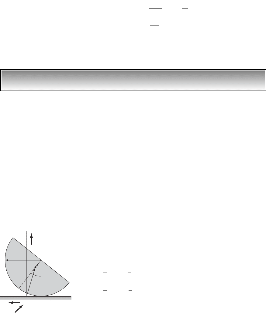
EXAMPLE 3.12
Governing equation for motion of a disk segment
For the half-disk shown in Figure 3.11, we will choose the coordinate u as the
generalized coordinate and establish the governing equation for the disc.
Through this example, we illustrate how the system kinetic energy and the sys-
tem potential energy can be approximated for “small” amplitude angular oscil-
lations, so that the final form of the governing equation is linear. During the
course of obtaining the governing equation, we determine the equivalent mass
and equivalent stiffness of this system. The natural frequency of the disc is
determined and it is shown that disc can be treated as a pendulum with a certain
effective length. After determining the equivalent system properties, we deter-
mine the governing equation of motion based on the last of Eqs. (3.47).
As shown in Figure 3.11, the half-disk has a mass m and a mass moment
of inertia J
G
about the center of mass G. The system is assumed to oscillate
without slipping. The point O is a fixed point, and the point of contact C is a
distance Ru from the fixed point for an angular motion u. The orthogonal unit
vectors i, j, and k are fixed in an inertial reference frame. The position vector
from the fixed point O to the center of mass G is given by
(a)
and the absolute velocity of the center of mass is determined from Eq. (a) to be
(b)
Then, using Eq. (1.24) and selecting the generalized coordinate q
1
u, the
system kinetic energy takes the form
(c)
Choosing the fixed ground as the datum, the system potential energy takes the
form
1
2
J
G
u
#
2
1
2
m3R
2
b
2
2bR cos u4u
#
2
1
2
J
G
u
#
2
1
2
m31R b cos u 2
2
b
2
sin
2
u4u
#
2
T
1
2
J
G
u
#
2
1
2
m1r
#
#
r
#
2
r
#
1R b cos u2u
#
i b sin uu
#
j
r 1Ru b sin u 2i 1R b cos u 2j
v
n
b
m
1
gL
1
a1
m
2
L
2
m
1
L
1
b
m
1
L
2
1
a1
2r
2
5L
1
2
b
씮
B
g
L
1
3.6 Lagrange’s Equations 101
OC
G
r
m, J
G
R
b
i
j
k
FIGURE 3.11
Half-disk rocking on a surface.

(d)
Note that the system kinetic energy and the system potential energy, which
are given by Eqs. (c) and (d), respectively, are not in the form of Eqs. (3.46a).
Small Oscillations about the Upright Position
If we use the expressions for the system kinetic energy and system potential
energy in Eq. (3.44), then the resulting equation of motion will be a nonlinear
equation. Since our final objective is to have a linear equation that can be used
to describe “small” amplitude angular oscillations about the upright position
of the disk (i.e., u
o
0), we express the angular displacement as
(e)
and expand the trigonometric terms sin u and cos u as the following Taylor-
series expansions:
(f)
Since u
o
0, Eqs. (f) become
(g)
In the expansions given by Eqs. (g), we have kept up to the quadratic terms
in , since quadratic terms in the expressions for kinetic energy and potential
energy lead to linear terms in the governing equations. On substituting Eqs.
(e) and (f) into the expressions (c) and (d), noting that , and retaining up
to quadratic terms in and in these expressions, we arrive at
(h)
On comparing Eqs. (h) with Eqs. (3.46), we see that while the kinetic en-
ergy is in the standard form, the potential energy is not in standard form be-
cause of the constant term. However, since the datum for the potential energy
is not unique, we can shift the datum for the potential energy from the fixed
ground of Figure 3.11 to a distance (R-b) above the ground. When this is done,
this constant term does not appear and, from Eqs. (h) and (3.46), we identify
that the equivalent inertia and stiffness properties of the system are
(i)k
e
mgb
m
e
J
G
m1R b2
2
V mg1R b2
1
2
mgbu
ˆ
2
T
1
2
3J
G
m1R b2
2
4u
ˆ
#
2
u
ˆ
#
u
ˆ
u
ˆ
#
u
#
u
ˆ
sin u u
ˆ
cos u 1
1
2
u
ˆ
2
sin u sin1u
o
u
ˆ
2 sin u
o
u
ˆ
cos u
o
1
2
u
ˆ
2
sin u
o
. . .
cos u cos1u
o
u
ˆ
2 cos u
o
u
ˆ
sin u
o
1
2
u
ˆ
2
cos u
o
. . .
u1t 2 u
o
u
ˆ
1t 2
V mg1R b cos u2
102 CHAPTER 3 Single Degree-of-Freedom Systems
Since the gravity loading has already been taken into account, the gener-
alized force is zero. Furthermore, since there is no damping, the equivalent
damping coefficient c
e
is zero. Hence, from Eqs. (3.47) and (i), we arrive at
the governing equation
(j)
Natural Frequency
From Eq. ( j), we find that the natural frequency is
(k)
On comparing the form of Eq. (k) to the form of the equation for the natural
frequency of a planar pendulum of length L
1
given by Eq. (m) of Exam-
ple 3.11, we note that Eq. (k) is similar in form to the natural frequency of a
pendulum with an effective length
(l)
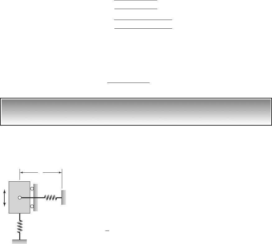
EXAMPLE 3.13
Governing equation for a translating system with a
pretensioned or precompressed spring
We revisit Example 2.8, and use Lagrange’s equations to derive the govern-
ing equation of motion for vertical translations x of the mass about the static-
equilibrium position of the system. Through this process, we will examine
how the horizontal spring with linear stiffness k
1
affects the vibrations. The
natural frequency of this system is also determined. The equation of motion
will be derived for “small” amplitude vertical oscillations; that is, |x/L| 1.
In the initial position, the horizontal spring is pretensioned with a tension
T
1
as shown in Figure 3.12, which is produced by an initial extension of the
spring by an amount d
o
; that is,
(a)
The kinetic energy of the system is
(b)
Next, we note that the potential energy is given by
(c)
where V
i
, i 1, 2, is the potential energy associated with the spring of stiff-
ness k
i
. Note that gravitational loading is not taken into account because we
V V
1
V
2
T
1
2
mx
#
2
T
1
k
1
d
o
L
e
J
G
m1R b2
2
mb
B
g
3J
G
m1R b2
2
4/mb
v
n
B
mgb
J
G
m1R b2
2
3J
G
m1R b2
2
4u
ˆ
$
mgbu
ˆ
0
3.6 Lagrange’s Equations 103
k
2
k
1
, T
1
L
x
m
FIGURE 3.12
Single degree-of-freedom system
with the horizontal spring under an
initial tension T
1
.
are considering oscillations about the static-equilibrium position. On substi-
tuting for V
1
and V
2
in Eq. (c), we arrive at
(d)
where is the change in the length of the spring with stiffness k
1
due to the
motion x of the mass. For |x/L| 1, as discussed in Example 2.8, this
change is
(e)
From Eqs. (d) and (e), the system potential energy is
(f)
The expression for potential energy contains terms up to the fourth
power of the displacement x, whereas the standard form given in Eqs. (3.46)
contains only a quadratic term. However, the kinetic energy is of the form
given in Eqs. (3.46). Hence, we will need to use Eq. (3.44) directly to obtain
the governing equation. To this end, we recognize that and find that
(g)
where we have made use of Eq. (a) and we have dropped the cubic term in x
since we have assumed that |x/L| 1.
Noting that the dissipation function D 0 and that the generalized force
Q
1
0, we substitute Eqs. (b) and (g) into Eq. (3.44) to obtain the following
governing equation of motion
(h)
From Eq. (h), we recognize the natural frequency to be
(i)
It is seen that the effect of a spring under tension, which is initially normal to
the direction of motion, is to increase the natural frequency of the system.
If the spring of constant k
1
is compressed instead of being in tension, then
we can replace T
1
by T
1
and Eq. (i) becomes
v
n
B
k
2
T
1
/L
m
mx
$
ak
2
T
1
L
bx 0
ak
2
T
1
L
bx
ak
2
k
1
d
o
L
bx
k
1
2
x
3
L
2
0V
0x
k
1
ad
o
L
2
a
x
L
b
2
ba
x
L
b k
2
x
q
1
x
V1x 2
1
2
k
1
ad
o
L
2
a
x
L
b
2
b
2
1
2
k
2
x
2
L a1
1
2
a
x
L
b
2
b L
L
2
a
x
L
b
2
¢L 2L
2
x
2
L L 21 1x/L 2
2
L
¢L
V1x 2
1
2
k
1
1d
o
¢L2
2
1
2
k
2
x
2
104 CHAPTER 3 Single Degree-of-Freedom Systems
(j)
From Eq. (j), it is seen that the natural frequency can be made very low by ad-
justing the compression of the spring with stiffness k
1
. At the same time, the
spring with stiffness k
2
can be made stiff enough so that the static displace-
ment of the system is not excessive. This type of system is the basis of at least
one commercial product.
14
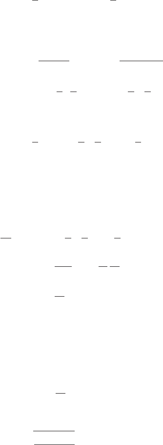
EXAMPLE 3.14 Equation of motion for a disk with an extended mass
We shall determine the governing equation of motion and the natural fre-
quency for the system shown in Figure 3.13, for “small” angular motions of
the pendulum. The system shown in Figure 3.13 is similar to the system
shown in Figure 3.9, except that there is an additional pendulum of length L
and rigid mass m that is attached to the disk. The disk rolls without slipping.
The position of fixed point O is chosen to coincide with the unstretched length
of the spring, the coordinate u is chosen as the generalized coordinate, and the
translation .
The kinetic energy of the system is given by
(a)
where the kinetic energy of the disk is given by Eq. (e) of Example 3.10. The
kinetic energy of the pendulum mass m is given by
(b)
where, based on the particle kinematics discussed in Section 1.2 and the first
of Eqs. (f) of Example 1.1, we have
(c)
On substituting for the velocity vector from Eq. (c) into Eq. (b) and executing
the scalar dot product, we obtain
(d)
1
2
m 31R
2
L
2
2LR cos u24u
#
2
1
2
m 3R
2
u
#
2
L
2
u
#
2
2LRu
#
2
cos u4
T
pendulum
1
2
m 31Ru
#
Lu
#
cos u2
2
L
2
u
#
2
sin
2
u4
V
m
1Ru
#
L u
#
cos u2i L u
#
sin uj
V
m
dr
m
dt
d
dt
31x L sin u2i 1L L cos u 2j4
T
pendulum
1
2
m 1V
m
#
V
m
2
T T
disk
T
pendulum
x Ru
v
n
B
k
2
T
1
/L
m
3.6 Lagrange’s Equations 105
14
Minus K Technology, 420 S. Hindry Ave., Unit E, Inglewood, CA, 90301 (www.minusk.com).
X
i
j
k
Y
Z
O
G
m
L
k
c
x
m
D
, J
G
2R
FIGURE 3.13
Disk that is rolling and translating and
has a rigidly attached extended mass.

Since the objective is to obtain the governing equation for “small” angular os-
cillations of the pendulum about the position , we retain up to quadratic
terms in Eq. (d). To this end, we expand the cos u term as
(e)
substitute Eq. (e) into Eq. (d), and retain up to quadratic terms to obtain
(f)
Making use of Eq. (e) of Example (3.10) and Eq. (f), we construct the system
kinetic energy from Eq. (a) as
(g)
The potential energy of the system is constructed as
(h)
where the datum for the potential energy of the pendulum is located at the bot-
tom position and we have used Eq. (2.36) with L/2 replaced by L. To describe
small oscillations of the pendulum, we use the expansion for the cos u term
given by Eq. (e) and retain up to quadratic terms in Eq. (h) to obtain
(i)
In this case, the dissipation function is given by
(j)
Comparing Eqs. (g), (i), and (j) to Eqs. (3.46), we find that the equivalent
system properties are given by
(k)
Thus, making use of the last of Eqs. (3.47) and Eqs. (k) and noting that the
generalized force Q
1
0, we arrive at the governing equation
(l)m
e
u
$
c
e
u
#
k
e
u 0
c
e
cR
2
k
e
kR
2
mgL
m
e
m1L R2
2
m
D
R
2
J
G
D
1
2
cx
#
2
1
2
cR
2
u
#
2
1
2
1kR
2
mgL2u
2
V
1
2
kR
2
u
2
1
2
mgLu
2
V
1
2
kx
2
mg1L L cos u2
1
2
kR
2
u
2
mgL11 cos u2
1
2
3m1L R 2
2
m
D
R
2
J
G
4u
#
2
T
1
2
m1L R 2
2
u
#
2
1
2
m
D
x
#
2
1
2
J
G
u
#
2
T
pendulum
1
2
m 3L
2
R
2
2LR4u
#
2
1
2
m1L R 2
2
u
#
2
cos u 1
1
2
u
2
###
u 0
106 CHAPTER 3 Single Degree-of-Freedom Systems
From Eqs. (k) and the first of Eqs. (3.48), we determine that the system natu-
ral frequency is
(m)
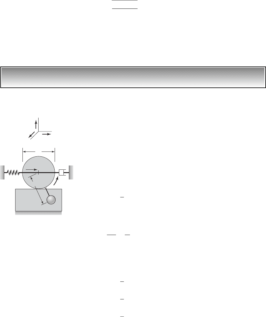
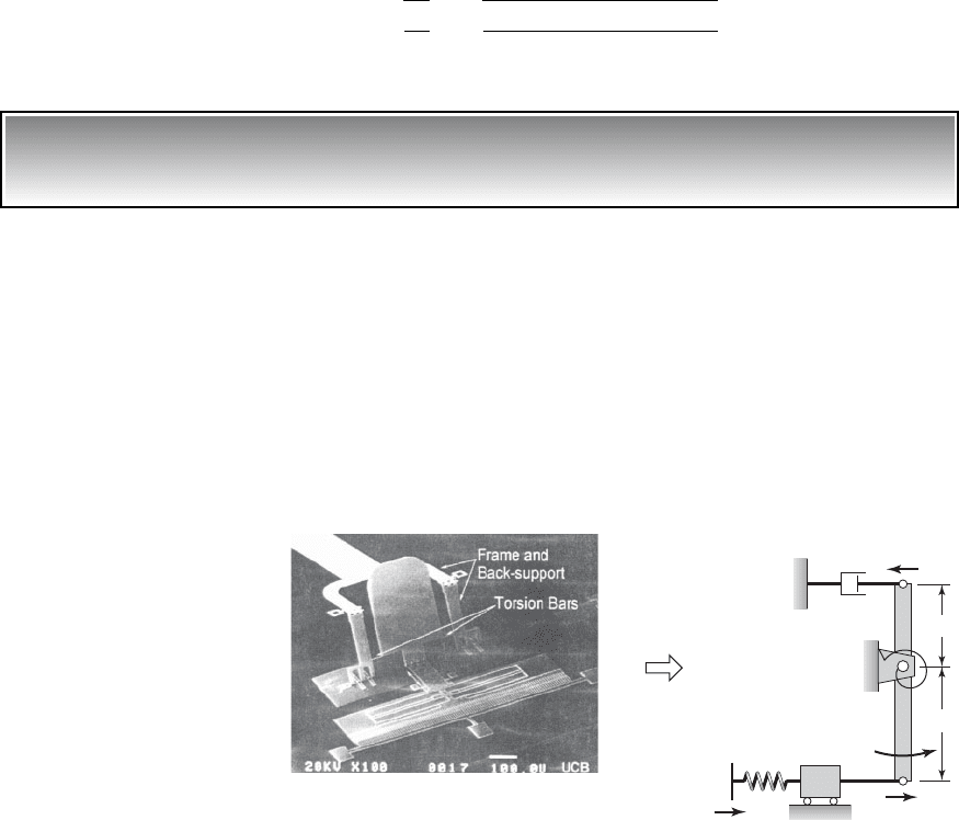
EXAMPLE 3.15
Lagrange formulation for a microelectromechanical system
(MEMS) device
We shall determine the governing equation of motion and the natural frequency
for the microelectromechanical system
15
shown in Figure 3.14. The mass m
2
is
the scanning micro mirror whose typical dimensions are 300 mm 400 mm.
This mass is modeled as a rigid bar. The torsion springs are rods that are 50 mm
in length and 4 mm
2
in area and are collectively modeled by an equivalent tor-
sion spring of stiffness k
t
in the figure. Mass m
1
is the mass of the electrostatic
comb drive, which is comprised of 100 interlaced “fingers.” The comb fingers
are 2 mm wide and 40 mm long. The comb drive is connected to the displace-
ment drive through an elastic member that has a spring constant k. The mass m
1
is connected to the bar m
2
by a rigid, weightless rod.
v
n
B
k
e
m
e
B
kR
2
mgL
m1L R 2
2
m
D
R
2
J
G
3.6 Lagrange’s Equations 107
L
1
k
c
J
o
, m
2
L
2
x
1
x
o
(t)
x
2
k
t
(b)(a)
MEMs device
O
m
1
FIGURE 3.14
(a) MEMS device and (b) single degree-of-freedom model. Source: From M.H.Kiang,
O.Solgaard, K.Y.Lau, and R.S.Muller, "Electrostatic Comb-Drive-Actuated Micromirrors for
Laser-Beam Scanning and Positioning", Journal of Microelectromechanical System, Vol. 7,
No.1, pp. 27–37 (March 1998). Copyright © 1998 IEEE. Reprinted with permission.
15
M.-H. Kiang, O. Solgaard, K. Y. Lau, and R. S. Muller, “Electrostatic Comb-Drive-Actuated
Micromirrors for Laser-Beam Scanning and Positioning,” J. Microelectromechanical Systems,
Vol. 7, No. 1, pp. 27–37 (March 1998).

We will use the angular coordinate f as the generalized coordinate, and
derive the equation of motion for “small” angular oscillations. The translation
x
o
(t) is prescribed, and the translations x
1
and x
2
are approximated as
(a)
The system potential energy is constructed as
(b)
where V
1
is the potential energy of the torsion spring, V
2
is the potential en-
ergy of the translation spring, and V
3
is the gravitational potential energy of
the bar. For “small” angular oscillations of the bar, Eq. (c) of Example 2.9 is
used to describe the bar’s potential energy. Thus, we arrive at
(c)
where we have made use of Eqs. (a). When L
2
L
1
, the effects of the increase
and decrease in the potential energy of each portion of the bar of mass m
2
cancel.
Next, the system’s kinetic energy is determined as
(d)
The system dissipation function is given by
(e)
where we have again made use of Eqs. (a). Comparing the forms of Eqs. (c),
(d), and (e) to Eqs. (3.46), we find that the potential energy is not in the stan-
dard form. Thus, we will make use of Eq. (3.44) to determine the governing
equation of motion. To this end, we find from Eq. (c) that
f
V
(f)
To obtain the governing equation of motion, we recognize that q
1
f,
substitute for the system kinetic energy and the dissipation function from
ck
t
kL
2
2
1
2
m
2
g 1L
2
L
1
2df kL
2
x
o
1t 2
k
t
f kL
2
1x
o
1t 2 L
2
f2
1
2
m
2
g 1L
2
L
1
2f
0V
0f
0
0f
c
1
2
k
t
f
2
1
2
k 1x
o
1t 2 L
2
f2
2
1
4
m
2
g1L
2
L
1
2f
2
d
D
1
2
cx
#
2
2
1
2
cL
1
2
f
#
2
1
2
1J
o
m
1
L
2
2
2f
#
2
T
1
2
J
o
f
#
2
1
2
m
1
x
#
1
2
1
2
J
o
f
#
2
1
2
m
1
L
2
2
f
#
2
1
2
k
t
f
2
1
2
k1x
o
1t 2 L
2
f2
2
1
4
m
2
g1L
2
L
1
2f
2
V
1
2
k
t
f
2
1
2
k1x
o
1t 2 x
1
2
2
1
4
m
2
g1L
2
L
1
2f
2
V V
1
V
2
V
3
x
2
L
1
f
x
1
L
2
f
108 CHAPTER 3 Single Degree-of-Freedom Systems

Eqs. (d) and (e), respectively, into Eq. (3.44), make use of Eq. (f), and note
that the generalized force Q
1
0. Thus,
(g)
where
From the inertia and stiffness terms of Eq. (g), we find that the system
natural frequency is given by
(h)
An experimentally determined value for the natural frequency of a typical
system is 2,400 Hz. If the rod connecting the mass m
1
to the bar were not as-
sumed rigid and weightless, one would need to consider additional coordi-
nates to describe the system of Figure 3.14. Systems with more than one de-
gree of freedom are treated in Chapters 7 to 9.
EXAMPLE 3.16
Equation of motion of a slider mechanism
16
We revisit the slider mechanism system of Example 2.2 and obtain the equa-
tion of motion of this system by using Lagrange’s equation. Gravity loading
is assumed to act normal to the plane of the system shown in Figure 3.15. The
mass m
s
slides along a uniform bar of mass m
l
that is pivoted at the point O.
A linear spring of stiffness k restrains the motions of the mass m
s
. Another
uniform bar of mass (m
b
m
e
) is pivoted at O, which is attached to a linear
spring of stiffness k
d
at one end and attached to the mass m
s
at the other end.
An excitation d(t) is imposed at one end of the spring with stiffness k
d
.
We choose the angular coordinate w as the generalized coordinate, and
we will determine the equation of motion in terms of this coordinate. The
geometry imposes the following constraints on the motion of the system:
(a)
At a first glance, although the slider mechanism appears to be a system that
would need more than one coordinate for its description, due to the con-
straints given by Eqs. (a), the system is single degree-of-freedom system that
can be described by the independent coordinate w.
a r1w2 cos b b cos w
r 1w2 sin b b sin w
r
2
1w 2 a
2
b
2
2ab cos w
v
n
B
k
e
m
e
B
k
t
kL
2
2
m
2
g 1L
2
L
1
2/2
J
o
m
1
L
2
2
k
e
k
t
kL
2
2
m
2
g1L
2
L
1
2/2
m
e
J
o
m
1
L
2
2
m
e
f
$
cL
1
2
f
#
k
e
f kL
2
x
o
1t 2
3.6 Lagrange’s Equations 109
16
J. Pedurach and B. H. Tongue, “Chaotic Response of a Slider Crank Mechanism,” J. Vibration
Acoustics, Vol. 113, pp. 69–73 (January 1991).
a
O
r
l
O'
e
m
e
m
l
Spring end
fixed to m
l
m
b
m
s
b
k
k
d
d(t)
FIGURE 3.15
Slider mechanism.