Balakumar Balachandran, Magrab E.B. Vibrations
Подождите немного. Документ загружается.


Critically Damped System: z 1
When z 1, we denote the system as critically damped; that is, c c
c
. The
solution to Eq. (4.2) in this case is given by Eq. (D.19); that is,
(4.7)
Overdamped System: z 1
When the damping factor z 1, the system is overdamped; that is, the damp-
ing coefficient c is larger than the critical damping coefficient c
c
. In this re-
gion, the solution to Eq. (4.2) is given by Eq. (D.9) with f(t) 0; that is,
(4.8)
where
(4.9)
Undamped System: z 0
When the damping factor z 0, the system is undamped; that is, the damp-
ing coefficient c 0. In this case, the solution to Eq. (4.2) is given by either
Eq. (D.24) or Eq. (D.25); that is,
(4.10)
and
(4.11)
respectively, where
(4.12)
We are now in a position to study the differences in the response of the
mass for the three different damping levels and to determine the effects of
the damping ratio on the rate of decay. To simplify matters, we shall assume
that the initial displacement X
o
0 and that the initial velocity V
o
0. Then,
after introducing the nondimensional time variable t v
n
t, we simplify
Eqs. (4.10), (4.3), (4.7), and (4.8) to, respectively,
z 0
x1t 2
V
o
/v
n
sin1t 2
w
d
¿ tan
1
v
n
X
o
V
o
A
o
¿
B
X
o
2
a
V
o
v
n
b
2
x1t 2 A
o
¿ sin1v
n
t w
d
¿ 2
x1t 2 X
o
cos1v
n
t2
V
o
v
n
sin1v
n
t2
v
d
¿ v
n
2z
2
1
x1t 2 X
o
e
zv
n
t
v
d
¿
3zv
n
sinh v
d
¿ t v
d
¿ cosh v
d
¿ t4 V
o
e
zv
n
t
v
d
¿
sinh v
d
¿ t
x1t 2 X
o
e
v
n
t
3V
o
v
n
X
o
4te
v
n
t
130 CHAPTER 4 Single Degree-of-Freedom System
0 z 1
z 1
z 1
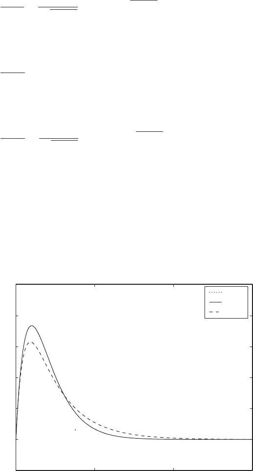
The time histories for the three damped cases are plotted in Figure 4.1, where
it is seen that when z 1, the displacement decays to its equilibrium position
in the shortest time. This characteristic is made use of, for example, in the de-
sign of dampers for doors. In addition, it is seen that for z 1 the response is
oscillatory, whereas for z 1 the response is not oscillatory. However, as z
increases, the magnitude of the peak amplitude decreases.
x1t 2
V
o
/v
n
1
2z
2
1
e
zt
sinh1t 2z
2
12
x1t 2
V
o
/v
n
te
t
x1t 2
V
o
/v
n
1
21 z
2
e
zt
sin1t 21 z
2
2
4.2 Free Responses of Undamped and Damped Systems 131
FIGURE 4.1
Response of a single degree-of-freedom system to an initial velocity for three different
values of z.
0 5 10 15
0.1
0
0.1
0.2
0.3
0.4
0.5
t
x(t)/(V
o
/
ω
n
)
ζ
1
ζ
1
ζ
1

In the absence of forcing, when z 0, the displacement response always
decays to the equilibrium position x(t) 0. However, this is not true when
z 0; the response of the system will grow with respect to time. This is an
example of an unstable response, which is discussed in Section 4.3.
Next, we present three examples that explore the free responses of under-
damped and critically damped systems in detail.
EXAMPLE 4.1
Free response of a microelectromechanical system
A microelectromechanical system has a mass of 0.40 mg, a stiffness of
0.08 N/m, and a negligible damping coefficient. The gravity loading is nor-
mal to the direction of motion of this mass. We shall determine and discuss
the displacement response of this system when there is no forcing acting on
this system and when the initial displacement is 2 mm and the initial velocity
is zero.
Since V
o
f(t) z 0, we see from Eq. (4.10) that the displacement
response has the form
(a)
where
(b)
From Eq. (b), the natural frequency is
rad/s
or
Substituting this value and the given value of initial displacement 2 mm into
Eq. (a) results in
(c)
Equation (c) is the displacement response. Based on the form of Eq. (a)
or Eq. (c), it is clear that the displacement is a cosine harmonic function that
varies periodically with time and has the period
x1t 2 2 cos114142.14t 2mm
f
n
v
n
2p
14142.14
2p
2250.8 Hz
v
n
B
0.08 N/m
0.40 10
9
kg
14142.14
v
n
B
k
m
x1t 2 X
o
cos1v
n
t2
132 CHAPTER 4 Single Degree-of-Freedom System
Design Guideline: The free response of a critically damped system
reaches its equilibrium or rest position in the shortest possible time.

From the form of Eq. (c), it is clear that the response does not decay, and
hence, the response does not settle down to the static-equilibrium position.
The system, instead, oscillates harmonically about this equilibrium position
with an amplitude of 2 mm.
EXAMPLE 4.2
Free response of a car tire
A wide-base truck tire is characterized with a stiffness of 1.23 10
6
N/m,
an undamped natural frequency of 30 Hz, and a damping coefficient of
4400 Ns/m. In the absence of forcing, we shall determine the response of the
system assuming non-zero initial conditions, evaluate the damped natural
frequency of the system, and discuss the nature of the response.
Let the mass of the tire be represented by m. Based on the equation of
motion derived in Chapter 3 for the system shown in Figure 3.1, the govern-
ing equation of motion of the tire system from the static equilibrium position
is given by Eq. (4.2); that is,
(a)
For this case,
rad/s
(b)
Since the damping factor is less than 1, the system is underdamped. Hence,
the solution for Eq. (a) is given by Eq. (4.4); that is, the displacement response
of the tire system about the static-equilibrium position is
(c)
where the constants A
o
and w
d
are determined by the initial displacement and
initial velocity as indicated by Eqs. (4.6). The damping factor z and the natu-
ral frequency v
n
are given by Eqs. (b), and the damped natural frequency v
d
is determined from Eq. (4.5) as
rad/s
The response given by Eq. (c) has the form of a damped sinusoid with a
period
T
d
2p
v
d
2p
177.5
0.0354 s
v
d
v
n
21 z
2
188.5021 0.337
2
177.5
x1t 2 A
o
e
zv
n
t
sin1v
d
t w
d
2
z
c
2mv
n
cv
n
2k
4400 N
#
s/m 188.50 rad/s
2 1.23 10
6
N/m
0.337
v
n
2p 30 188.50
d
2
x
dt
2
2zv
n
dx
dt
v
n
2
x 0
T
2p
v
n
1
f
n
1
2250.8
444.29 ms
4.2 Free Responses of Undamped and Damped Systems 133
Thus, the tire oscillates back and forth about the static-equilibrium position
with a period of 35.4 ms. As time unfolds, the amplitude of the displacement
response decreases exponentially with time, and in the limit,
because of the exponential term. Thus, after a fast decay, the tire system set-
tles down to the static-equilibrium position.
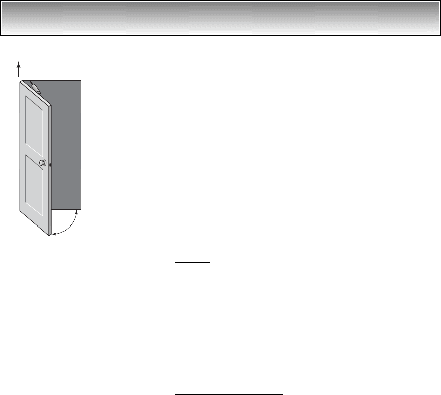
EXAMPLE 4.3
Free response of a door
A door shown in Figure 4.2 undergoes rotational motions about the vertical
axis pointing in the k direction. From Eq. (3.13), the governing equation of
motion of this system is
(a)
where the mass moment of inertia J
door
20 kgm
2
, the viscous damping pro-
vided by the door damper is 48 Nms/rad, and the rotational stiffness of the
door hinge is 28.8 Nm/rad. We shall determine the response of this system
when the door is opened with an initial velocity of 4 rad/s from the initial po-
sition u 0. We shall then plot this response as a function of time and discuss
its motion.
Equation (a) is written in the form of Eq. (4.2) by dividing through by the
inertia J
door
to obtain
(b)
where
(c)
For the given values of the parameters, the damping factor and the natural fre-
quency are, from Eqs. (c),
(d)
Hence, the system is critically damped. The displacement response is given
by Eq. (4.7); that is,
z
48 N m
#
s/rad
2 20 kg
#
m
2
1.2 rad/s
1.0
v
n
B
28.8 N
#
m/rad
20 kg
#
m
2
1.2 rad/s
v
n
B
k
t
J
door
z
c
t
2J
door
v
n
u
$
2zv
n
u
#
v
n
2
u 0
J
door
u
$
c
t
u
#
k
t
u 0
lim
t씮 q
x1t 2 lim
t씮 q
3A
o
e
zv
n
t
sin1v
d
t w
d
24 0
134 CHAPTER 4 Single Degree-of-Freedom System
FIGURE 4.2
Door motions.
k
Door
(e)
Upon substituting the given initial conditions, and rad/s
and the value of the natural frequency from Eq. (d) in Eq. (e), we arrive at the
displacement response of the door
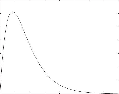
(f)
This response is plotted as a function of time in Figure 4.3. From this
figure, it is evident the free-response of this critically damped system quickly
reaches the static-equilibrium position u 0 after the time exceeds about one
period of the undamped oscillation of the system; that is, when T 2p/v
n
5.24 s. The peak displacement amplitude occurs at (t
peak
) 0, or t
peak
1/1.2
0.833 s. As expected of a critically damped system, the motion is not peri-
odic and does not oscillate about the equilibrium position.
In the rest of the section, the responses of underdamped single degree-of-
freedom systems to certain prescribed initial displacements, initial velocities,
or both simultaneously are addressed in detail; that is, systems for which
0 z 1.
From the general form of the solution for 0 z 1, we know that non-
zero initial conditions will result in oscillations that decay exponentially with
time. This solution is examined for several situations that occur in the design
u
#
u1t 2 4te
1.2t
rad
u
#
10 2 4u10 2 0
u1t 2 u10 2e
v
n
t
3u
#
10 2 v
n
u10 24te
v
n
t
4.2 Free Responses of Undamped and Damped Systems 135
FIGURE 4.3
Displacement time history of the door in Figure 4.2.
0 1 2 3 4 5 6 7 8
0
0.2
0.4
0.6
0.8
1
1.2
1.4
t (s)
u (rad)

of single degree-of-freedom systems with a prescribed initial velocity and a
prescribed initial displacement.
4.2.2 Initial Velocity
We now examine the free response of a single degree-of-freedom system with
a prescribed initial velocity. When a system is subjected to an initial velocity
only, we set X
o
0 in Eqs. (4.6). This leads to the following amplitude and
phase
and, therefore, Eq. (4.4) becomes
(4.13)
The velocity and acceleration of the mass are, respectively,
(4.14)
where
(4.15)
and Eq. (D.12) has been used.
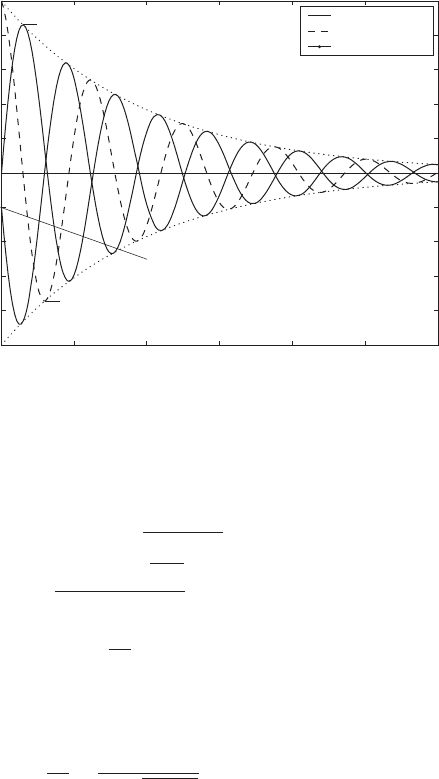
The displacement, velocity, and acceleration responses given by Eqs.
(4.13) and (4.14) are plotted in Figure 4.4. The location of the displacement
extrema and the velocity extrema seen in this figure are determined as dis-
cussed next.
Extrema of Displacement Response
The displacement has an extremum (maximum or minimum) at those times
t
dm
for which
(4.16)
The solution to Eq. (4.16) is
(4.17)
Therefore, from Eq. (4.13), it follows that
v
d
t
dm
w pp
p 0, 1, 2, . . .
x
#
1t
dm
2
V
o
e
zv
n
t
dm
21 z
2
sin1v
d
t
dm
w2 0
w tan
1
21 z
2
z
or
w sin
1
21 z
2
x
$
1t 2 a1t2
V
o
v
n
e
zv
n
t
21 z
2
sin1v
d
t 2w2
x
#
1t 2 v1t2
V
o
e
zv
n
t
21 z
2
sin1v
d
t w2
x1t 2
V
o
e
zv
n
t
v
d
sin1v
d
t2
w
d
0
A
o
V
o
v
d
136 CHAPTER 4 Single Degree-of-Freedom System
4.2 Free Responses of Undamped and Damped Systems 137
(4.18)
where we have used Eq. (4.15).
The largest displacement occurs when p 0, or at
(4.19)
Extrema of Velocity Response
In a similar manner, we find the times t
vm
at which the velocity is a maximum/
minimum, which are determined from the condition that the acceleration is
zero; that is, a(t
vm
) 0. Making use of the second of Eqs. (4.14), these times
are found to be
(4.20)
and, from the first of Eqs. (4.14), the corresponding velocities are determined
as
(4.21)
The use of Eq. (4.21) is illustrated in Example 4.4.
x
#
1t
vm
2 11 2
p1
V
o
e
12wpp2/tan w
p 0, 1, 2, . . .
v
d
t
vm
2w pp
p 0, 1, 2, . . .
t
d,max
w
v
d
w
v
n
21 z
2
112
p
V
o
v
n
e
1wpp2/tan w
p 0, 1, 2, . . .
V
o
e
zv
d
t
dm
/1
1 z
2
v
d
sin1w pp 2
x1t
dm
2 x
max/min
V
o
e
zv
n
t
dm
v
d
sin1v
d
t
dm
2
FIGURE 4.4
Time histories of displacement, velocity, and acceleration of a system with prescribed initial
velocity V
o
.
0 5 10 15 20 25 30
–
1
–
0.8
–
0.6
–
0.4
–
0.2
0
0.2
0.4
0.6
0.8
1
v
n
t
dm
=
f/(1
–
z
2
)
1/2
v
n
t
vm
=
2f/(1
–
z
2
)
1/2
v
n
t
–
sin(2
f
)/(1
–
z
2
)
1/2
x(t)v
n
/V
o
, v(t)/V
o
, a(t)/(v
n
V
o
)
e
–
zv
n
t
Displacement
Velocity
Acceleration

Force Transmitted to Fixed Surface
We shall now determine the dynamic component of the force transmitted to
the base of a single degree-of-freedom system such as that shown in Fig-
ure 3.1. This force is given by Eq. (3.10); that is,
(4.22)
Upon substituting Eqs. (4.13) and (4.14) into Eq. (4.22), we obtain
(4.23)
At t 0, the reaction force acting on the base is determined from Eq. (4.23)
to be
(4.24)
Thus, when the mass of a single degree-of-freedom system is subjected to an
initial velocity, the force is instantaneously transmitted to the base. This un-
realistic characteristic is a property of modeling the system with a spring and
viscous damper combination in parallel. The viscous damper essentially
“locks” with the sudden application of the velocity and is thereby momentar-
ily rigid. This temporary rigidity shorts the spring and instantaneously trans-
mits the force to the base. Representing a support by a combination of a lin-
ear spring and linear viscous damper in parallel is called the Kelvin-Voigt
model, which is one type of elementary viscoelastic model. A second type of
elementary viscoelastic model, called the Maxwell model, consists of a linear
spring and a linear viscous damper in series, and this model is discussed in
Example 4.7.
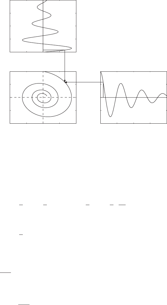
State-Space Plot and Energy Dissipation
The values of the displacements and velocities corresponding to these max-
ima and minima can also be visualized in a state-space plot, which is a graph
of the displacement versus the velocity at each instant of time. This graph for
the system considered here is shown in Figure 4.5. As time unfolds, the tra-
jectory initiated from a set of initial conditions is attracted to the equilibrium
position located at the origin (0, 0). When 0, the state-space plot in terms
of the nondimensional displacement and nondimensional velocity is a circle.
If this plot is made in terms of dimensional quantities, it will be an ellipse.
We now show how the energy dissipated by the system in the time interval
0 t t
d,max
can be determined. The system of interest is a spring-mass-
damper system, as shown in Figure 3.2, which is translating back and forth
along the x-axis. The energy dissipated by the system is equal to the difference
between the sum of the kinetic energy and the potential energy in the final state
and the sum of the kinetic energy and the potential energy in the initial state.
Noting that the potential energy in the initial state is zero, and the kinetic en-
ergy in the final state is zero, the energy that is dissipated is the difference be-
tween the initial kinetic energy and the potential energy that is stored in the
F
R
10 2
2zkV
o
v
d
sin1w 2
2zkV
o
v
n
F
R
1t 2
kV
o
e
zv
n
t
v
d
32z sin1v
d
t w2 sin1v
d
t24
F
R
cx
#
kx
138 CHAPTER 4 Single Degree-of-Freedom System
4.2 Free Responses of Undamped and Damped Systems 139
spring at t
d,max
. The initial energy is the kinetic energy of the mass, which has
been imparted a velocity V
o
. The energy stored in the spring is a function of the
displacement x(t
d,max
). Thus, the energy E
diss
that is dissipated is
(4.25)
where we have used Eqs. (4.18). Thus, the fraction of the total energy that has
been dissipated is
(4.26)
where the initial energy E
init
is given by
(4.27)
From Eq. (4.26), it is seen that the fraction of the total energy dissipated is
only a function of the system’s damping factor z, since the angle w is deter-
mined only by the damping factor.
E
init
mV
o
2
2
E
diss
E
init
31 e
2w/tan w
4
1
2
mV
o
2
31 e
2w/tan w
4
Final potential energy
Initial kinetic
energy
E
diss
1
2
mV
o
2
1
2
k3x1t
d,max
24
2
1
2
mV
o
2
1
2
k
V
o
2
v
n
2
e
2w/tan w
FIGURE 4.5
State-space plot of a single degree-of-freedom system with a prescribed
initial velocity V
o
.
0 5 10 15 20
t
1
v
n
t
v(t)/V
o
1
0.5 0 0.5 1
0
5
10
15
20
t
1
x(t)v
n
/V
o
v
n
t
1
0.5 0 0.5 1
1
0.5
0
0.5
1
1
0.5
0
0.5
1
x(t)v
n
/V
o
v(t)/V
o
(x(0),v(0))
⎫
⎬
⎭
⎫
⎪
⎬
⎪
⎭