Balakumar Balachandran, Magrab E.B. Vibrations
Подождите немного. Документ загружается.

520 CHAPTER 8 Multiple Degree-of-Freedom Systems
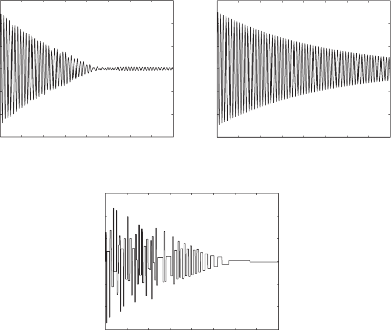
FIGURE 8.32
Pulse response of a particle damper for z 0.004, m
21
0.05, k
21
100, c
21
20, and f
o
50: (a) displacement response of m
1
with particle damper; (b) displacement response of m
1
without particle damper; and (c) velocity response of m
2
.
0 50 100 150
(a)
200 250 300 350 400
1.5
1
0.5
0
0.5
1
1.5
y
1
()
(b)
0 50 100 150 200 250 300 350 400
1.5
1
0.5
0
0.5
1
1.5
y
1
()
(c)
0 50 100 150 200 250 300 350 400
3
2
1
0
1
2
3
dy
2
/d
Response to Harmonic Forcing with and without Particle Damper:
Frequency-Domain Results
Next, we shift our attention to the response of the particle-damped system to
a harmonic forcing. We let p(t) cos(t) in Eqs. (8.157) and study the re-
sponse in the following manner. For different values of the forcing amplitude
f
o
, we numerically obtain a solution of Eqs. (8.157) over a range of excitation
frequency and obtain the solution for 0 t t
max
, where t
max
is the cho-
sen time range. This numerically obtained solution is denoted as y
1
(, t, f
o
).
The transient portion of the solution, which in all of the cases considered oc-
curs over the interval t 0.25 t
max
, is ignored. The remaining portion of the
solution is considered to be the steady-state solution. By using this steady-
state solution, we obtain the root-mean-square (rms) value from the relation
(8.159)
Then, for a given value of f
o
, we plot y
rms
(⍀, f
o
) as a function of ⍀ to obtain
the results shown in Figure 8.33. To generate the results, we have selected a
value of t
max
⫽ 2000, which gives about 315 periods of oscillations when
⍀⫽1 over the range 0 ⱕ t ⱕ t
max
.
y
rms
1⍀, f
o
2⫽
G
1
0.75t
max
冮
t
max
0.25t
max
y
2
1
1⍀, t, f
o
2dt
8.6 Vibration Absorbers 521
0.7 0.8 0.9 1 1.1 1.2
5
10
15
20
25
30
35
40
45
Ω
Amplitude response
y
rms
(Ω,f
o
)/f
o
y
lin(rms)
(Ω)/f
o
(a)
y
rms
(Ω,f
o
)/f
o
y
lin(rms)
(Ω)/f
o
(b)
0.7 0.8 0.9 1 1.1 1.2
5
10
15
20
25
30
35
40
45
Ω
Amplitude response
y
rms
(Ω,f
o
)/f
o
y
lin(rms)
(Ω)/f
o
0.7 0.8 0.9 1
(c)
1.1 1.2
5
10
15
20
25
30
35
40
45
Ω
Amplitude response
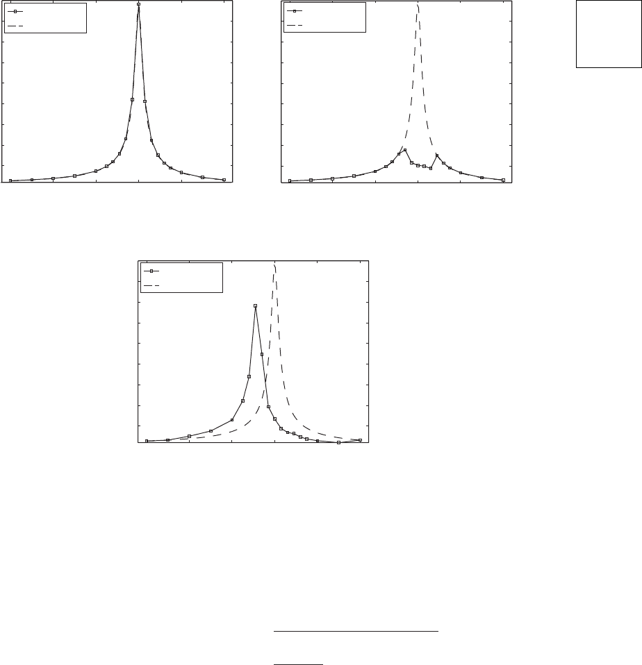
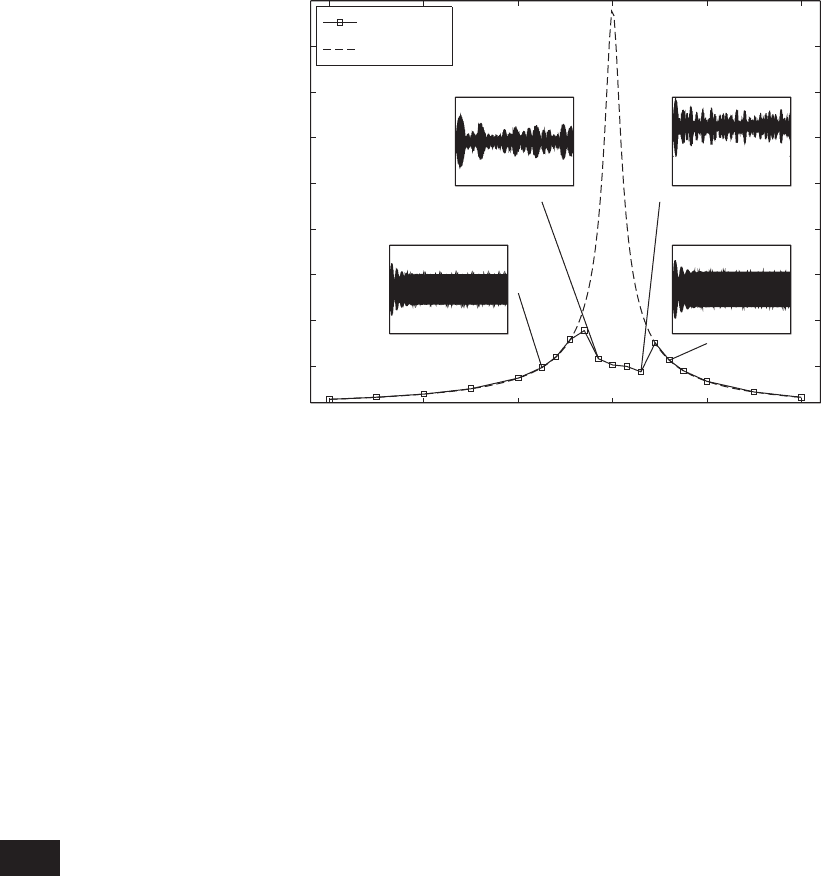
FIGURE 8.33
Amplitude response of a particle damper for z ⫽ 0.008, m
21
⫽ 0.08, k
21
⫽ 100, and c
21
⫽ 20: (a) f
o
⫽ 0.01; (b) f
o
⫽ 0.05; and
(c) f
o
⫽ 0.2. For comparison, the values of y
lin(rms)
(⍀) also are given.
Au: We have not
made any correc-
tions in this page,
as the scanned pdf
does not contain
this page.

For comparison purposes, we also have plotted in Figure 8.33 the rms
value of the system without the particle damper (i.e., h g 0 in Eq.
(8.157)), which is given by
where
(8.160)
Without taking recourse to nonlinear analysis, we shall try to understand
these results on the basis of the understanding gained for a harmonically
forced single degree-of-freedom system considered in Chapter 5.
Insights Based on Steady-State Response of Harmonically
Forced System without Damper
We first consider the linear case where h g 0; that is, the case where the host
system is not damped by the particle damper. Then, the solution to Eq. (8.157)
is given by Eq. (5.17) with the sine forcing replaced by the cosine forcing. The
magnitude of the steady-state displacement amplitude of m
1
is given by
(8.161)
From Figure 8.30, we see that m
1
must move at least an amount (or
equivalently, an amount such that ) for m
2
to come in contact
with the spring k
2
. In nondimensional terms, this means that f
o
must have a
magnitude such that f
o
H() 1. In addition, H() 1 for
provided that 0 z 0.7071. Hence, in this frequency region, the particle
damper is not effective until f
o
H() 1, and one can expect the response of
the host system to be close to that of the system without the damper when
f
o
H() 1. Noting that the maximum value of H() is about 1/2z, it can be
stated that the particle damper is not activated when f
o
/(2z) 1 for all . In
addition, it is always activated when f
o
1 for and for 0
z 0.7071. Noting that the total mass of the system with the particle damper
is m
1
+ m
2
, the nondimensional (linear) natural frequency of this combined
system is , which is lower than that the natural frequency
of the system without the particle damper. Hence, when the nonlinear effects
of the particle damper are activated and the nonlinear effects are not pro-
nounced, the system’s maximum response occurs at a frequency location
lower than the natural frequency of the single degree-of-freedom system.
For the system corresponding to Figure 8.33a, f
o
H() 1 for all values
of , and, therefore, the particle damper is not activated and the response of
the host system without the damper matches that of the system with the
damper. The two amplitude response functions are virtually identical. For the
system corresponding to Figure 8.33c, we have the opposite situation; that is,
f
o
H() 1 for almost all . In this case, the nondimensional natural
frequency of the system is shifted lower to a value of
. For the system corresponding to Figure 8.33c, the1/ 21 0.08
0.962
1/ 21 m
21
1/ 21 m
21
22 4z
2
22 4z
2
0y
1
1 20 1
0x
1
0 d
0y
1
1 20 f
o
H12
H12
1
211
2
2
2
12z2
2
y
lin1rms2
1 2 f
o
H12/ 12
522 CHAPTER 8 Multiple Degree-of-Freedom Systems
particle damper is activated, and we find that the maximum magnitude of the
amplitude response function is decreased by about 22%. However, the re-
sponse of the system with the damper exceeds the response of the system
without the damper in the low-frequency region. For the system correspon-
ding to Figure 8.33b, we see that the particle damper is activated only in the
range 0.96 1.04. When is outside this region, the responses of the
system with and without the particle damper are virtually identical.
Insights Based on Transient Response of Harmonically
Forced System without the Particle Damper
The results shown in Figures 8.33b and 8.33c cannot be explained entirely by
the magnitude of f
o
H(), which corresponds to the steady-state response. One
also needs to consider the transient response of the system. In order to look into
this, we return again to the linear case. The solution to Eq. (8.157) for the lin-
ear case with p(t) cos(t) is given by Eqs. (5.14) and (5.15) and plotted in
Figures 5.3 and 5.4. From these results, we see that it takes a finite period of
time for the transient portion of the response to decay, after which the steady-
state response is attained. It was found from Figures 5.3 and 5.4 that for certain
combinations of system parameters the peak amplitudes of the transient por-
tion of the response exceeded the steady-state amplitude. A similar effect oc-
curs in the nonlinear case, except that the consequences are very different. We
first examine the responses in the time domain of the system to a forcing with
frequency 0.9 and amplitude f
o
0.2; the corresponding results are shown
in Figure 8.34. These time-domain results correspond to one data point in Fig-
ure 8.33c. According to the results shown in Figure 8.33c and our earlier dis-
cussion, the particle damper should not have been activated, since f
o
H()
0.2H(0.9) 1. However, from Figure 8.34a, we find that the earliest time t
1
8.6 Vibration Absorbers 523
FIGURE 8.34
Response of the system with particle damper for z 0.008, m
21
0.08, k
21
100, c
21
20, 0.9, and f
o
0.2:
(a) displacement of mass m
1
and (b) velocity of mass m
2
.
0 100 200 300
(a) (b)
400 500
3
2
1
0
1
2
3
y
1
()
0 100 200 300 400 500
4
3
2
1
0
1
2
3
dy
2
/d
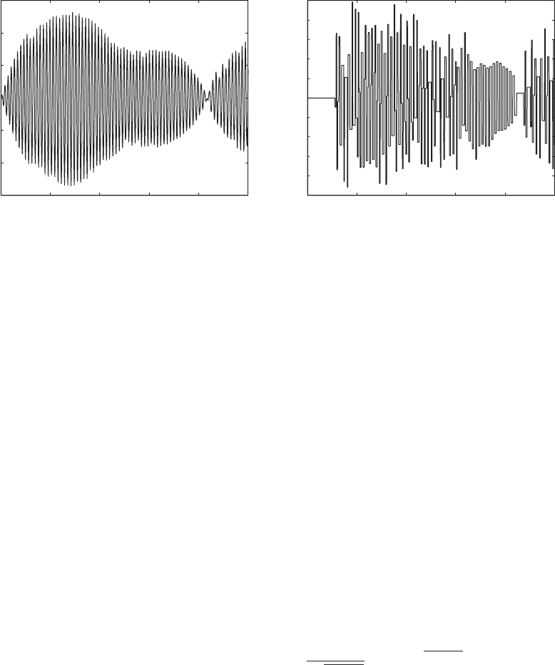
that the peak amplitude of exceeds unity is at t
1
11.198, where y
1
(t
1
)
1.000; therefore, the particle damper is activated as indicated by the
sudden jump in velocity at t t
1
11.198 and remains activated for
all time thereafter. The same activation mechanism applies when 0.97
and f
o
0.05, which corresponds to one data point in Figure 8.33b. Again,
for this combination of parameters, f
o
H() 0.05H(0.97) 1 and the
particle damper should not have been activated. These results are shown in
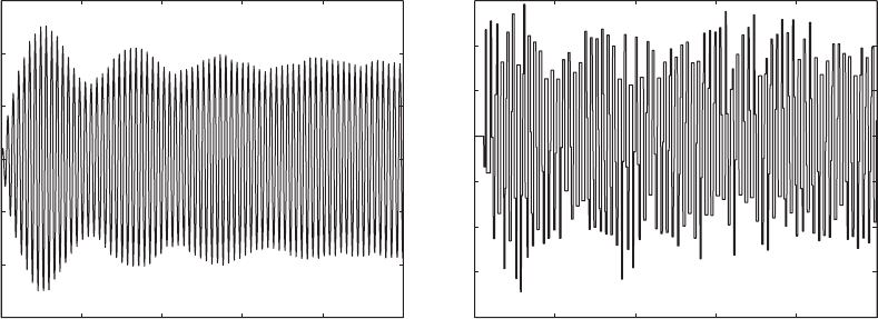
Figure 8.35, where we find that the earliest time that the peak amplitude of
exceeds unity is at t
1
55.708, where y
1
(t
1
) 1.000. It is seen that
the time response is entirely different than that obtained for the previous case.
In this case, no steady-state condition is reached; the results suggest aperiodic
motions.
In both of these cases, the overshoot from the transient response of the
system is the reason why the system response exceeds unity. Since the system
acts as a single degree-of-freedom system until t t
1
is reached, one can use
Eqs. (5.14) and (5.15) to determine the time at which the magnitude of the re-
sponse exceeds one; that is, the earliest time t
1
when
Need for Nonlinear Analysis
In Figure 8.36, we show the time-domain results superimposed at different
frequency locations for the system corresponding to Figure 8.33b. The mo-
tions corresponding to 0.925 and 1.06 are periodic as in the
case without the damper. In both of these cases, the particle damper is not
f
o
H12`cos 1t
1
u1 22
e
zt
1
21 z
2
cos At
1
21 z
2
u
ct
1 2B`1 0
0y
1
1t 20
y
#
2
1t 2
0y
1
1t 20
524 CHAPTER 8 Multiple Degree-of-Freedom Systems
0 100 200 300
(a) (b)
400 500
1.5
1
0.5
0
0.5
1
1.5
y
1
()
0 100 200 300 400 500
2.5
2
1.5
1
0.5
0
0.5
1
1.5
2
2.5
dy
2
/d
FIGURE 8.35
Response of the system with particle damper for z 0.008, m
21
0.08, k
21
100, c
21
20, 0.97, and f
o
0.05:
(a) displacement of mass m
1
and (b) velocity of mass m
2
.
effective in attenuating the motions of the host system. However, at
0.985 and 1.03, where the particle damper is effective in damping the
host system, the motions are aperiodic. The aperiodic motions, which proba-
bly occur due to aperiodic impacts between the particle damper and the host
system, could be a key reason for the effectiveness of the particle damper. To
understand the characteristics of these motions as well as to determine when
and how they will occur, one would need to consider stability of motions.
40
It
is possible that the system may have more than one response for a chosen set
of excitation parameter values, and each response may have associated sets of
initial conditions that take one to it.
8.7 VIBRATION ISOLATION: TRANSMISSIBILITY RATIO
In many machinery-mounting situations, the single degree-of-freedom model
given in Section 5.7 is inadequate because the formulation does not take into
account the stiffness of the flooring. To have a more realistic model, let us
suppose that m
1
is the mass of the flooring and m
2
is the mass of the machin-
ery as shown in Figure 8.37. In some instances, the machinery is connected to
a seismic mass, which in turn is connected via springs to the structure, usu-
ally the ground.
8.7 Vibration Isolation: Transmissibility Ratio 525
FIGURE 8.36
Amplitude response of a particle damper for z 0.008, m
21
0.08, k
21
100, c
21
20,
and f
o
0.05 along with time-domain responses at different excitation frequencies.
0.7 0.8 0.9 1 1.1
1.2
5
10
15
20
25
30
35
40
45
Ω
Amplitude response
0 1000 2000
1
0
1
0 1000 2000
2
0
2
y
1
2
1
0
2
y
1
y
1
1
0
1
y
1
0 1000 2000
0 1000 2000
y
rms
(Ω,f
o
)/f
o
y
lin(rms)
(Ω)/f
o
40
See, for example, Nayfeh and Balachandran, 1995, ibid.
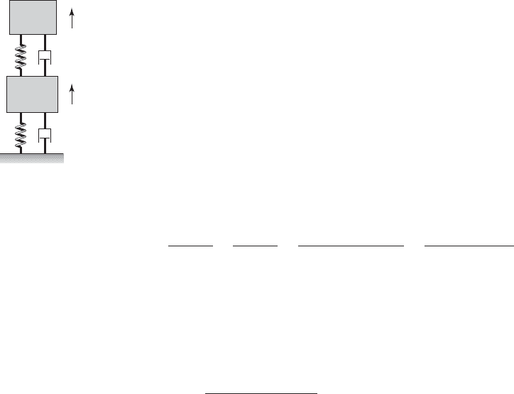
The objective is to determine the various parameters of the system so
that the force transmitted to the ground or the structure that is supporting the
flooring
41
is as small as practical. To do this, we need to examine the ratio of
the magnitude of the force transmitted to the ground f
base
(t) to the magnitude
of the force applied to the machinery f
2
(t). If motions about the static-
equilibrium position are considered, then the equations governing the system
shown in Figure 8.37 are represented by Eqs. (8.60) when we set the spring
constant k
3
, the damping coefficient c
3
, and the force f
1
(t) to zero. Then, the
force transmitted to the ground is given by Eq. (8.89b).
The required transfer function is F
base
(s)/F
2
(s). To obtain this transfer
function, we set all initial conditions to zero and assume that the force applied
to m
2
is an impulse; that is, f
2
(t) F
o
d(t). Then, using Eqs. (8.90), (8.71), and
(8.75), we obtain
(8.162)
where D
2
(s) is given by Eq. (8.74). The transmissibility ratio is defined as
(8.163)
To obtain this ratio TR, we set s j in Eq. (8.162) and substitute the result
into Eq. (8.163) to obtain
(8.164)
where D
2
( j) and B( j) are given by Eqs. (8.102).
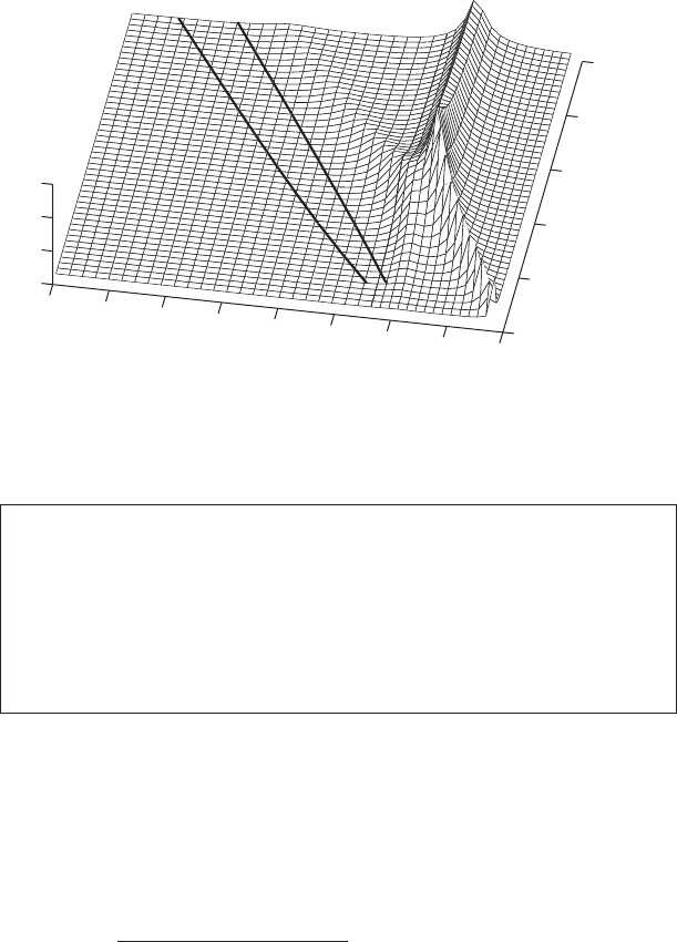
The results obtained from Eq. (8.164) are plotted in Figure 8.38 for the
case where z
1
z
2
0.08 and the mass ratio m
r
0.1. The transmissibility
ratio TR is shown as a function of the frequency ratio v
r
and the nondimen-
sional excitation frequency ratio . A point on this graph is interpreted as the
magnitude of the transmissibility ratio for flooring represented by the m
1
-k
1
-c
1
system in Figure 8.37 and harmonic excitation acting on the mass m
2
at the
nondimensional frequency . The transmissibility ratio then provides the
magnitude of the harmonic force transmitted to the ground. In addition, solid
lines have been drawn to delineate the regions where TR is less than or equal
to a certain fraction of the force applied to m
2
that reaches the ground or floor-
ing supports. Consider the case where TR 0.1. Comparing these results with
the TR value of a single degree-of-freedom system given in Figure 5.34 we see
thattogetaTR of 10% we need to have 3.32 in a single degree-of-
freedom system. On the other hand, in the case of a two degree-of-freedom
system, we see that for 1.5 and v
r
0.5 we will attain the same levels. In
other words, the natural frequency of m
2
by itself has to be less than half of
the support/flooring. We also note from Figure 8.38 that for a given TR, the
operating frequency of the machinery is almost linearly proportional to v
r
.
TR `
12z
1
j12B1j2
m
r
D
2
1j2
`
TR 0T
R
1j20
T
R
1s 2
F
base
1s 2
F
2
1s 2
F
base
1s 2
F
o
k
1
12z
1
s 12X
1
1s 2
F
o
12z
1
s 12B1s 2
m
r
D
2
1s 2
526 CHAPTER 8 Multiple Degree-of-Freedom Systems
x
1
x
2
, f
2
(t)
k
2
c
2
k
1
c
1
m
2
m
1
Machinery
Floor
Ground
FIGURE 8.37
Representative two degree-of-
freedom system for vibration
transmission model.
41
J. A. Macinante, Seismic Mountings for Vibration Isolation, John Wiley & Sons, NY, Chapter 8
(1984).
We now examine how the system parameters can be selected to attenuate
the peak magnitude of the force transmitted to the ground when an impulsive
force is applied to the mass m
2
. This situation arises, for example, in factories
where it is necessary to isolate forges and punch presses. To determine this,
we take the inverse Laplace transform of Eq. (8.162). Before doing so, how-
ever, we rewrite Eq. (8.162) using Eq. (8.64) as follows:
(8.165)
We see from Eq. (8.165) and an examination of D
2
(s) that when m
r
1, m
r
has a very small effect on T
R
. Again using available numerical procedures,
42
representative numerically obtained results for the inverse of Eq. (8.165) are
given in Figure 8.39. For small values of the frequency ratio v
r
, it is seen that
the transient oscillations have a high-frequency component, which appears to
“ride” on top of a low-frequency oscillation. However, as v
r
increases, this
characteristic diminishes. In addition, we see that the nondimensional peak
T
R
1s 2
v
r
12z
1
s 1212z
2
s v
r
2
D
2
1s 2
8.7 Vibration Isolation: Transmissibility Ratio 527
Design Guideline: For the transmissibility of a dynamic force
through a flexible flooring system, which is modeled as a two degree-
of-freedom system with m
r
0.1, to be less than 10%, the nondimen-
sional excitation frequency of the disturbing force should be greater
than 1.2 v
r
, where v
r
is the ratio of the system uncoupled natural
frequencies.
42
The MATLAB function ilaplace from the Symbolic Math Toolbox was used.
0
0.5
1
1.5
2
2.5
0
0.5
1
1.5
2
2.5
3
3.5
4
0
5
10
15
v
r
Ω
TR
0.3
TR
0.1
TR
FIGURE 8.38
Transmissibility ratio for two degree-of-freedom system with m
r
0.1 and z
1
z
2
0.08.
[Solid lines represent constant values of TR.]
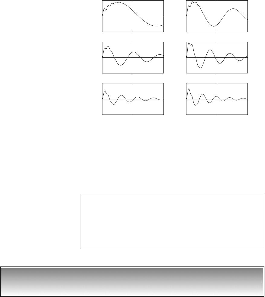
amplitude is nearly equal to v
r
. Furthermore, we see that the introduction of the
seismic mass m
1
can provide a much larger attenuation of the peak magnitude
of the force applied to m
2
, when compared to that of a single degree-of-freedom
system. Recall from Section 6.2 that for a single degree-of-freedom system, the
most attenuation that we could attain was about 18% for z 0.25.
EXAMPLE 8.18
Design of machinery mounting to meet transmissibility
ratio requirement
A 150 kg machine is to be operated at 500 rpm on a platform that is modeled
as a single degree-of-freedom system with the following mass, stiffness, and
damper values: m
1
3000 kg, k
1
2 10
6
N/m, and c
1
7500 N/(m/s). The
machinery mounting is to be determined so that the transmissibility ratio does
not exceed 0.1.
528 CHAPTER 8 Multiple Degree-of-Freedom Systems
0 50 100
0.05
0
0.05
v
r
0.05
v
r
0.15
v
r
0.25 v
r
0.3
v
r
0.2
v
r
0.1
0 50 100
0.1
0
0.1
0 50 100
0.2
0
0.2
0 50 100
0.2
0
0.2
0 50 100
0.5
0
0.5
0 50 100
0.5
0
0.5
T
R
(
)T
R
(
)T
R
(
)
T
R
(
)T
R
(
)T
R
(
)
FIGURE 8.39
Magnitude of an impulse force
transmitted to the base of a two
degree-of-freedom system:
z
1
z
2
0.1.
Design Guideline: The peak transmissibility of a shock loading
through a lightly damped flooring system to the ground is approxi-
mately equal to the ratio v
r
. Therefore, the ratio should be as small as
possible, which is equivalent to having the uncoupled natural frequency
of the system attached to the flooring be much greater than the natural
frequency of the flooring by itself.

From the given values, we have that
(a)
We pick a mounting with negligible damping factor; that is, one for
which
(b)
We now use Eq. (8.164) to determine the value of v
r
that provides a trans-
missibility ratio that is less than 0.1 at 2.03. For the choice of mounting
with negligible damping factor, we find from Eqs. (8.102) that
(c)
On substituting Eqs. (c) into Eq. (8.164), we arrive at
(d)
Making use of Eqs. (a) by substituting the values for , z
1
, and m
r
into
Eq. (d), we arrive at
(e)
Equation (e) is solved numerically
43
for the value of v
r
that gives a value of
TR 0.1; this value is v
r
0.9741. Thus, since
(f)
the largest value of k
2
is
(g) 94.9 10
3
N/m
k
2
m
2
v
2
n2
m
2
1v
r
v
n1
2
2
1150 kg2 10.9741 25.82 rad/s 2
2
v
n2
v
r
v
n1
TR `
10.05 0.00982 j2v
2
r
0.64 0.0404 j 10.166 0.00982 j2v
2
r
`
TR `
12z
1
j12m
r
v
2
r
m
r
1
4
j2z
1
3
31 m
r
v
2
r
v
2
r
4
2
j2z
1
v
2
r
v
2
r
2
`
4
j2z
1
3
31 m
r
v
2
r
v
2
r
4
2
j2z
1
v
2
r
v
2
r
31 m
r
v
2
r
v
2
r
4z
1
z
2
v
r
4
2
j32z
2
v
r
2z
1
v
r
4v
2
r
D
2
1j2
4
j32z
1
2z
2
v
r
m
r
2z
2
v
r
4
3
m
r
v
2
r
B1j2 2z
2
m
r
v
r
jm
r
v
2
r
z
2
0
v
v
n1
1500 rev/min 2112p rad/rev2/160 s/min22
25.82 rad/s
2.03
z
1
c
1
2m
1
v
n1
7500 N/1m/s2
2 3000 kg 25.82 rad/s
0.048
v
n1
B
k
1
m
1
B
2 10
6
N/m
3000 kg
25.82 rad/s
m
r
m
2
m
1
150 kg
3000 kg
0.05
8.7 Vibration Isolation: Transmissibility Ratio 529
43
The MATLAB function fzero was used.