Balakumar Balachandran, Magrab E.B. Vibrations
Подождите немного. Документ загружается.

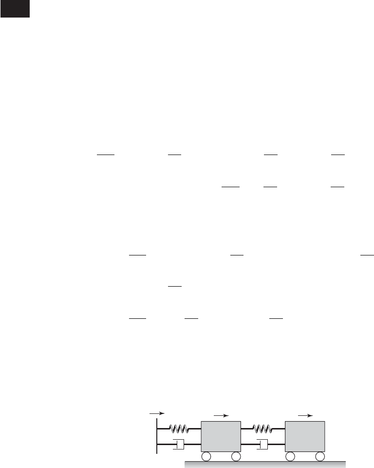
8.8 SYSTEMS WITH MOVING BASE
Another way to determine the efficacy of a two degree-of-freedom isolation
system is to compare the magnitude of the peak (maximum) displacement of
m
2
to the magnitude of the peak displacement of the ground.
44
To analyze this
type of situation, we consider the base supporting the two degree-of-freedom
system to be a moving base as shown in Figure 8.40. In analyses of such sys-
tems, one usually assumes that the masses are initially at rest and that there
are no applied forces directly on the inertial elements, and x
3
(t) is given. We
return to Eqs. (8.60) and modify them to account for the moving base. Thus,
Eqs. (8.60) become
(8.166)
After using the nondimensional quantities of Eqs. (7.41) and (8.61), Eqs.
(8.166) are rewritten as
(8.167)
Then, taking the Laplace transform of Eqs. (8.167) and solving for X
1
(s)
and X
2
(s), which are the transforms of x
1
(t) and x
2
(t), respectively, we find
that
d
2
x
2
dt
2
2z
2
v
r
dx
2
dt
v
2
r
x
2
2z
2
v
r
dx
1
dt
v
2
r
x
1
0
2z
1
dx
3
dt
x
3
0
d
2
x
1
dt
2
12z
1
2z
2
m
r
v
r
2
dx
1
dt
11 m
r
v
2
r
2x
1
2z
2
m
r
v
r
dx
2
dt
m
r
v
2
r
x
2
m
2
d
2
x
2
dt
2
c
2
dx
2
dt
k
2
x
2
c
2
dx
1
dt
k
2
x
1
0
m
1
d
2
x
1
dt
2
1c
1
c
2
2
dx
1
dt
1k
1
k
2
2x
1
c
2
dx
2
dt
2
k
2
x
2
c
1
dx
3
dt
k
1
x
3
0
530 CHAPTER 8 Multiple Degree-of-Freedom Systems
44
This analysis also has application in determining the dynamic response of seated humans. See
for example, X. Wu, S. Rakheja, and P.-E. Boileau, “Analysis of Relationships between Bio-
dynamic Response Functions,” J. Sound Vibration, Vol. 226, No. 3, pp. 585–606, 1999.
k
2
c
2
x
1
(t)
x
3
(t)
x
2
(t)
k
1
c
1
m
1
m
2
Moving
base
FIGURE 8.40
Two degree-of-freedom system with moving base.

(8.168)
where D
2
(s) is given by Eq. (8.74), C(s) is given by Eqs. (8.64), E
2
(s) is given
by Eq. (8.82), and
(8.169)
Comparing Eqs. (8.169) and (8.90), we see that k
1
K
3
(s) is the Laplace trans-
form of the total force generated by the moving base.
To compare the responses of the single degree-of-freedom system with a
moving base to that of a two degree-of-freedom system with a moving base,
we assume that the displacement of the base is a half-sine wave as shown in
Figure 6.25 and given by Eq. (b) of Example 6.8; that is,
(8.170)
where
o
v
o
/v
n1
, t
o
v
n1
t
o
, and t
o
p/v
o
. We shall determine the re-
sponse of m
2
. Assuming that x
3
(0) 0 for convenience, and using transform
pair 10 in Table A of Appendix A to obtain the Laplace transform of Eq.
(8.170), it is found that
(8.171)
Then K
3
(s), which is given by Eq. (8.169), becomes
(8.172)
After substituting Eq. (8.172) in Eq. (8.168), the response of the mass m
2
is
(8.173)
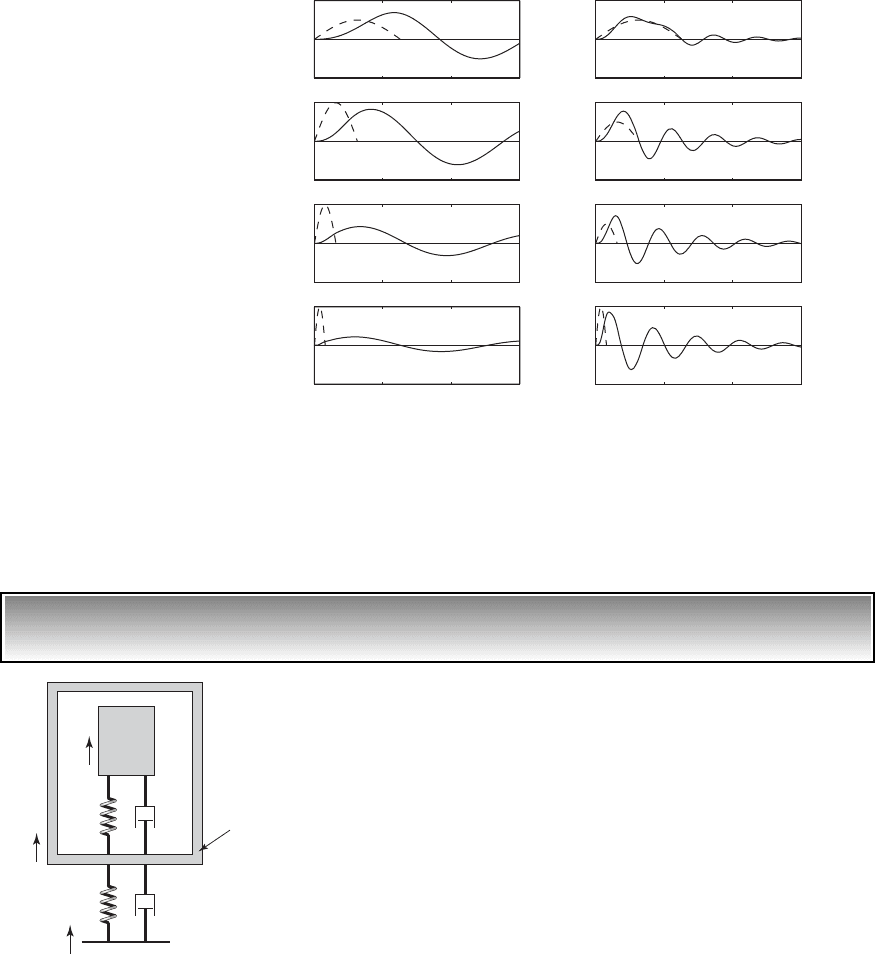
The numerically obtained inverse Laplace transform
45
of Eq. (8.173) is
shown in Figure 8.41. We see that as the duration of the half-sine wave pulse
decreases, the amplitude of m
2
decreases. This behavior is opposite to what
takes place during the base excitation of a single degree-of-freedom system,
where as the pulse duration decreased the peak displacement of the mass in-
creased. (Recall Figure 6.22.) We see, then, that the interposition of m
1
and its
spring and damper act as a mechanical filter, decreasing the amount of rela-
tively high frequency energy generated by the half-sine wave pulse from be-
ing transferred to m
2
. Thus, a two degree-of-freedom system with appropri-
ately chosen parameters can be an effective isolator of ground vibrations
compared to a single degree-of-freedom system.
X
2
1s 2
o
X
o
C1s 212z
1
s 1211 e
ps/
o
2
1s
2
2
o
2D
2
1s 2
K
3
1s 2
X
o
o
12z
1
s 1211 e
ps/
o
2
s
2
2
o
X
3
1s 2
X
o
o
11 e
ps/
o
2
s
2
2
o
x
3
1t 2 X
o
sin 1
o
t23u1t2 u1t t
o
24
K
3
1s 2 12z
1
s 12X
3
1s 2 2z
1
x
3
10 2
X
2
1s 2
K
3
1s 2C1s2
D
2
1s 2
X
1
1s 2
K
3
1s 2E
2
1s 2
D
2
1s 2
8.8 Systems with Moving Base 531
45
The MATLAB function ilaplace from the Symbolic Math Toolbox was used.
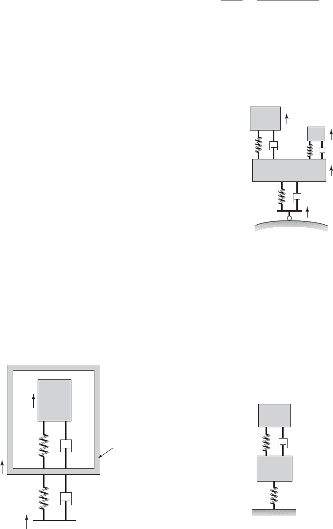
EXAMPLE 8.19 Isolation of an electronic assembly
We shall now consider the isolation of electronic components.
46
In this two
degree-of-freedom system, m
1
is the outer casing of an electronic assembly as
shown in Figure 8.42. Inside the casing, there is a flexibly supported elec-
tronic component modeled as a system with a mass m
2
, stiffness k
2
, and
viscous damping c
2
. The outer casing is elastically mounted as shown in Fig-
ure 8.42, usually to a base that is a relatively stiff structural member. The
movement of the structural member subjects the entire system to a displace-
ment. Typically, the mass ratio m
r
is much less than one and the uncoupled
natural frequencies of the systems are such that v
r
3.
Let the relative displacement between masses m
1
and m
2
be defined by
(a)
Then, for a given value d that specifies the maximum amplitude ratio,
z
2
1t 2 x
2
1t 2 x
1
1t 2
532 CHAPTER 8 Multiple Degree-of-Freedom Systems
0 50 100 150
2
0
2
x
2
()/X
o
x
2
()/X
o
x
2
()/X
o
x
2
()/X
o
x
2
()/X
o
x
2
()/X
o
x
2
()/X
o
x
2
()/X
o
Ω
o
0.05
Ω
o
0.1
Ω
o
0.2
0 50 100 150
1
0
1
0 50 100 150
1
0
1
0 50 100 150
1
0
1
0 50 100 150
2
0
2
0 50 100 150
2
0
2
0 50 100 150
2
0
2
0 50 100 150
1
0
1
(a)
(b)
Ω
o
0.4
Ω
o
0.05
Ω
o
0.1
Ω
o
0.2
Ω
o
0.4
FIGURE 8.41
Displacement response of m
2
when a half-sine wave displacement is applied to the
system base for m
r
0.1 and z
1
z
2
0.1: (a) v
r
0.05 and (b) v
r
0.2.
k
1
x
3
x
1
(t)
x
2
(t)
c
1
k
2
c
2
m
2
m
1
Base
FIGURE 8.42
Model of an electronic system con-
tained in a package that is subjected
to a base disturbance.
46
A. M. Veprik and V. I. Babitsky, “Vibration Protection of Sensitive Electronic Equipment from
Harsh Harmonic Vibration,” J. Sound Vibration, Vol. 238, No. 1, pp. 19–30 (2000).

8.8 Systems with Moving Base 533
(b)
we shall find the value of the damping factor z
1
so that the ratio
(c)
is a minimum. We assume that v
r
, m
r
, and z
2
are given. In practical cases,
z
2
1. Then, from Eqs. (8.168) and (8.169) we have that
(d)
The respective amplitude-response functions are obtained by setting s j
in Eq. (d) and then taking the absolute values. Thus, we obtain
(e)
We shall again use the optimization approach mentioned in Section 8.6.
If the maximum value of the X
13
occurs at
1
and that of Z
23
at
2
, then the
objective is to find the value of z
1
that makes the maximum value Z
23
(
2
) a
minimum value subject to the requirement that X
13
(
1
) d, when the values
of d, z
2
, v
r
, and m
r
are given. This is stated as follows:
(f)
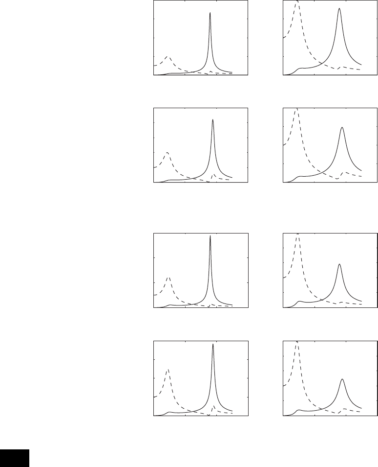
The results for several combinations of d, z
2
, v
r
, and m
r
are shown in Fig-
ures 8.43 and 8.44. We see that we get large attenuation of the maximum rel-
ative amplitude when we compare these results to those obtained for a single
degree-of-system given by Eq. (5.82) for the same damping ratio z
2
. For the
small values of z
2
used in these numerical examples, 0.05 and 0.01, we see
that the maximum values are approximately proportional to 1/(2z
2
). There-
fore, the maximum amplitudes would be 10 and 50, respectively. Also, the
values of j
1
that are required to obtain these reductions are attainable in
practice.
X
13
1
1
2 d
Subjectto: z
1
0
min
z
1
max
Z
23
12
5Z
23
1 26
0Z
23
1 20 `
12z
1
j 12
D
2
1j2
1C1j2 E
2
1j22`
0X
13
1 20 d `
12z
1
j 12E
2
1j2
D
2
1j2
`
Z
23
1s 2
X
2
1s 2
X
3
1s 2
X
1
1s 2
X
3
1s 2
12z
1
s 12
D
2
1s 2
1C1s2 E
2
1s 22
X
13
1s 2
X
1
1s 2
X
3
1s 2
12z
1
s 12E
2
1s 2
D
2
1s 2
0Z
23
1 20 `
Z
2
1j2
X
3
1j2
`
d 0X
13
1 20 `
X
1
1j2
X
3
1j2
`
534 CHAPTER 8 Multiple Degree-of-Freedom Systems
0 2 4 6
0
2
4
6
8
m
r
0.05
2
0.01 m
r
0.05
2
0.05
m
r
0.15
2
0.01 m
r
0.15
2
0.05
1,opt
0.307
1,opt
0.322
1,opt
0.322
1,opt
0.307
X
13
, Z
23
X
13
Z
23
0 2 4 6
0
0.5
1
1.5
2
X
13
, Z
23
X
13
Z
23
0 2 4 6
0
1
2
3
4
5
Ω
X
13
, Z
23
X
13
Z
23
0 2 4 6
0
0.5
1
1.5
2
Ω
X
13
, Z
23
X
13
Z
23
FIGURE 8.43
Optimum value of z
1
for several
combinations of m
r
and z
2
when
v
r
3.5 and 0X
13
(
1
) 0 d 2.0.
FIGURE 8.44
Optimum value of z
1
for several
combinations of m
r
and z
2
when
v
r
3.5 and 0X
13
(
1
) 0 d 2.5.
0 2 4 6
0
2
4
6
X
13
, Z
23
X
13
Z
23
0 2 4 6
0
0.5
1
1.5
2
2.5
X
13
, Z
23
X
13
Z
23
0 2 4 6
0
1
2
3
4
Ω
X
13
, Z
23
X
13
Z
23
0 2 4 6
0
0.5
1
1.5
2
2.5
Ω
X
13
, Z
23
X
13
Z
23
m
r
0.05
2
0.01
m
r
0.15
2
0.01 m
r
0.15
2
0.05
m
r
0.05
2
0.05
1,opt
0.229
1,opt
0.24
1,opt
0.24
1,opt
0.229
8.9 SUMMARY
In this chapter, we illustrated how the responses of linear multiple degree-of-
freedom systems could be determined by using the normal-mode approach,
Laplace transforms, and the state-space formulation. For the nonlinear multi-
ple degree-of-freedom systems treated in this chapter, the solutions were nu-
merically determined. The responses of multiple degree-of-freedom systems
to harmonic, step, and impulse excitations were also examined. The notions
of resonance, frequency-response functions, and transfer functions intro-
duced in the earlier chapters for single degree-of-freedom systems were re-
visited and discussed for multiple degree-of-freedom systems. For linear vi-
bratory systems, it was shown how the frequency-response functions can be
used to design vibration absorbers, mechanical filters, and address issues such
as base isolation and transmission ratio. A brief introduction to the design of
vibration absorbers based on nonlinear-system behavior was also presented.
Exercises 535
EXERCISES
Section 8.2.1
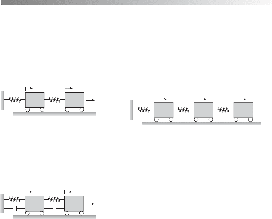
8.1 Consider the twodegree-of-freedomsystem shown
in Figure E8.1, where a forcing f
2
is imposed on the
mass m
2
.Form
1
m
2
1 kg, k
1
2 N/m, k
2
1 N/m,
and f
2
F
2
sinvt N, use the normal-mode approach to
determine the solution of the system.Assume that all of
the initial conditions are zero.
8.2 Consider the twodegree-of-freedomsystem shown
in Figure E8.2, where m
1
m
2
1 kg, k
1
2 N/m, k
2
1 N/m, c
1
0.4 N/m/s, c
2
0.2 N/m/s, and f
2
f
2
(t).
Starting with Eq. (7.1b), uncouple these equations by
using the modal matrix and present the uncoupled sys-
tem of equations.
conditions are zero and ignore the transient portion of
the response.
8.4 Use the normal-mode approach to determine a
solution for the response of the three degree-of-
freedom system shown in Figure 8.4 when an impulse
f
2
F
2
d(t) is imposed on mass m
2
. Assume that all
of the initial conditions are zero and that m
1
m
2
m
3
m and that k
1
k
2
k
3
k.
k
2
f
2
x
1
x
2
k
1
m
1
m
2
FIGURE E8.1
FIGURE E8.4
FIGURE E8.2
k
2
f
2
x
1
x
2
k
1
c
1
c
2
m
1
m
2
k
2
x
1
x
2
k
1
m
1
m
2
k
3
x
3
m
3
8.3 Use the normal-mode approach to determine a so-
lution for the response of system discussed in Exer-
cise 8.2 when an harmonic forcing f
2
10 sin(20t) N
is imposed on mass m
2
. Assume that all of the initial
8.5 Repeat Exercise 8.4 with an impulse f
1
F
1
d(t)
imposed on mass m
1
instead of mass m
2
.
Section 8.2.2
8.6 Consider the three degree-of-freedom system
shown in Figure E8.6. The different system parameter
values are as follows: J
o1
1 kg m
2
, J
o2
4 kg m
2
,
J
o3
1 kg m
2
, k
t1
k
t2
10 N m/rad, and k
t3
5 N m/rad. Assume that the damping matrix is pro-
portional to the inertia matrix; that is,
where a 0.5. When the external moment M
o
(t) is
absent, determine the response of this system by using
the normal-mode approach for each of the following
C
c
t1
00
0 c
t2
0
00c
t3
S aC
J
O1
00
0 J
O2
0
00J
O3
S
#
##
##
sets of initial conditions and discuss the participation
of different modes in each case.
a) f
1
(0) f
2
(0) f
3
(0) 1 rad
b) f
1
(0) f
3
(0) 1 rad, f
2
(0) 0.5 rad
f
#
1
10 2 f
#
2
10 2 f
#
3
10 2 0 rad/s.
f
#
3
10 2 0 rad/s,f
#
1
10 2 f
#
2
10 2
and then solve for the response amplitudes X
1
( jv) and
X
2
( jv) from the governing equations of motion.
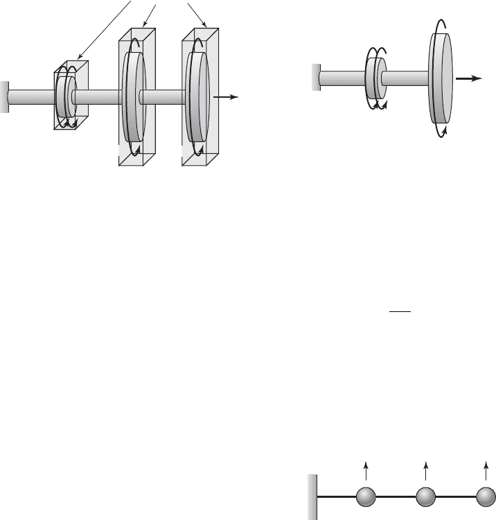
8.9 Consider the system of flywheels shown in Fig-
ure E8.9. For an applied moment M
o
(t) M
1
cosvt,
determine a solution for the response of the system by
using the direct approach presented in Section 8.2.3.
536 CHAPTER 8 Multiple Degree-of-Freedom Systems
k
t2
k
t1
1
2
c
t2
c
t3
c
t1
J
o1
J
o2
J
o3
M
o
(t)
Oil housing
k
t3
k
3
8.7 Consider the damped system of Exercise 8.2 and
set the forcing amplitude to zero. Examine the free
oscillations of this system by using the normal mode
for the following sets of initial conditions and discuss
the participation of different modes in each case:
a)
b) and
Section 8.2.3
8.8 Consider the twodegree-of-freedomsystem shown
in Figure E8.2 where m
1
m
2
1 kg, k
1
2 N/m,
k
2
1 N/m, c
1
0.4 Ns/m, and c
2
0.2 Ns/m. To
determine the response of this damped system to a
harmonic excitation, one can assume the excitation to
be of the form
which is referred to as a complex-valued excitation
because of the e
jvt
term. To determine the steady-state
solution for the response of this system, assume a so-
lution of the form
e
x
1
1t 2
x
2
1t 2
f e
X
1
1jv2
X
2
1jv2
fe
jvt
f
2
1t 2 F
2
e
jvt
x
#
2
10 2 0 m/s.x
#
1
10 2
x
1
10 20.2 m, x
2
10 2 0.2 m,
x
#
1
10 2 x
#
2
10 2 0 m/sx
1
10 2 x
2
10 2 0.2 m,
FIGURE E8.6
FIGURE E8.9
FIGURE E8.10
k
t1
1
2
k
t2
k
J
o1
J
o2
M
o
(t)
Flywheel 1
Flywheel 2
8.10 Consider the system shown in Figure E8.10 in
which the three masses m
1
, m
2
, and m
3
are located on
a uniform cantilever beam with flexural rigidity EI.
The inverse of the stiffness matrix for this system
, which is called the flexibility matrix, is given by
If the masses of the system are all identical; that is,
m
1
m
2
m
3
m, then determine the response of
this system when it is forced sinusoidally at the loca-
tion of mass m
2
with a forcing amplitude F
2
and an ex-
citation frequency v.
3K 4
1
L
3
3EI
C
27 14 4
14 8 2.5
4 2.5 1
S
3K 4
m
1
LL L
m
2
m
3
y
3
y
2
y
1
8.11 Consider the three degree-of-freedom system
shown in Figure E8.4. Assume that a harmonic forc-
ing f
2
F
2
cosvt is imposed on the mass m
2
. Deter-
mine if the mass m
1
can have a zero response at any of
the excitation frequencies.
8.12 For the system given in Exercise 8.1, carry out the
following: (a) determine a solution for the response of
this system by using the direct approach discussed in
Section 8.2.3 and (b) construct the frequency-response
functions H
12
() and H
22
() and plot these functions
as a function of the nondimensional excitation fre-
quency .
8.13 For the system given in Exercise 8.2, carry out
the following: (a) determine a solution for the re-
sponse of this system by using the direct approach
discussed in Section 8.2.3 and (b) construct the
frequency-response functions H
11
() and H
21
() and
plot these functions as a function of the nondimen-
sional excitation frequency .
8.14 Based on the response amplitudes determined
in Exercise 8.8, construct the frequency-response
functions
where is the nondimensional excitation frequency.
Plot graphs of the amplitudes and phases of the each
of these functions as a function of , compare them
to the plots of frequency-response functions deter-
mined in Exercise 8.1, and discuss their differences
and similarities.
Section 8.3
8.15 Put the linearized system governing “small”
amplitude motions of the pendulum-absorber system
of Exercise 7.1 in state-space form.
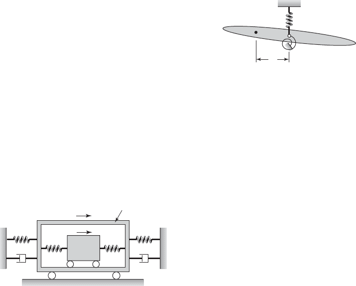
8.16 Derive the governing equations of motion for the
system shown in Figure E8.16 and present them in
state-space form.
G
22
1j2 X
2
1j2/F
2
G
12
1j2 X
1
1j2/F
2
8.17 Obtain a state-space form of the equations of
motion governing “small” amplitude motions of the
pendulum-absorber system shown in Figure E7.10.
Assume that oscillations about the static-equilibrium
position corresponding to the bottom position of the
pendulum are of interest.
8.18 Present the governing equations of motion for
“small” oscillations of the airfoil system shown in
Figure E8.18 in state-space form. In this system, the
stiffness of the translation spring is k, the stiffness of
the torsion spring is k
t
, G is the center of the mass of
the airfoil located a distance l from the attachment
point, m is the mass of the airfoil, and J
G
is the mass
moment of inertia of the airfoil about the center of
mass. Use the generalized coordinates y and u to
obtain the equations of motion, where y is the verti-
cal translation of the point O and u is the angular
oscillation about an axis normal to the airfoil plane.
Exercises 537
FIGURE E8.16
FIGURE E8.18
x
1
x
2
k
2
k
3
k
4
k
1
c
1
c
4
m
1
m
2
8.19 The damping matrix given in Exercise 8.6 is al-
tered so that the damping matrix now has the follow-
ing structure
Determine the responses of the flywheels for the iner-
tia and stiffness parameters given in Exercise 8.6 and
the initial conditions in case (a) of Exercise 8.6.
8.20 Consider the two degree-of-freedom system
with two different damping models treated in Exam-
ple 8.9 and obtain the state matrix for this system.
Study the eigenvalues and eigenvectors of this state
matrix for the systems with constant modal damping
and arbitrary damping models. Also, compare these
C
c
t1
00
0 c
t2
0
00c
t3
S C
0.2J
O1
00
0 0.6J
O2
0
0 0 0.2J
O3
S
l
m, J
G
G
k
O'
O
k
t
eigenvalues and eigenvectors with those for the un-
damped system and discuss them.
Section 8.5
8.21 Study the micromechanical filter of Example 8.13
and graph the amplitude response of the microme-
chanical filter similar to that shown in Figure 8.16 for
k
21
0.1 and z
1
0.0015.
8.22 For the system of Exercise 8.12, verify that the
frequency-response functions determined by using
the unit impulse excitation f
2
(t) d(t) agree with
those determined in that problem.
Section 8.6.1
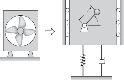
8.23 An industrial-fan system, a model of which is
shown in Figure E8.23, is found to experience unde-
sirable vibrations when operated at 600 rpm. It is as-
sessed that these undesirable vibrations are due to a
mass unbalance in the fan, and it is estimated the mass
unbalance m
o
2 kg is located at a distance e 0.5 m
from the point O shown in Figure E8.23. Design a vi-
bration absorber for this industrial-fan system with the
restriction that the mass of the absorber cannot exceed
75 kg.
575 rpm to 625 rpm and (b) the response amplitude of
the absorber mass should not exceed 25 mm.
8.25 A machine has a mass of 150 kg and a natural fre-
quency of 150 rad/s. An absorber mass of 30 kg and a
spring-damper combination is to be attached to this
machine, so that the machine can be operated in as
wide a frequency range as possible around the ma-
chine’s natural frequency. Determine the optimal pa-
rameters for the absorber.
8.26 In order to attenuate oscillations of telecommu-
nication towers, tuned vibration absorbers are typi-
cally used. The second natural frequency of a repre-
sentative telecommunication tower is 0.6 Hz and the
third natural frequency of this tower is 1.5 Hz. Design
two optimal absorbers; one to be effective in a fre-
quency range that includes 0.6 Hz and another to be
effective in a frequency range that includes 1.5 Hz.
The mass ratio for each absorber can be picked to lie
in the range 0.02 to 0.05.
8.27 An optical platform is found to be experience un-
desirable vibrations at a frequency of 100 Hz. The as-
sociated magnitude of the disturbance acting on the
platform is estimated to be 100 N. Design a spring-
mass system as an absorber for this system with the
constraint that the absorber response amplitude can-
not exceed 5 mm.
Section 8.6.2
8.28 A rotary engine experiences disturbances at the
sixth harmonic of the rotating speed of the system.
Determine the pendulum length of a centrifugal ab-
sorber for this system.
Section 8.6.3
8.29 Determine the free responses of the bar-slider
system described by Eqs. (8.144) for the following
parameter values: m 0.5, z 0.20, and v
c
0.5,
1.5, 2, and 2.5. Assume that in each case, the motions
are initiated from u(0) 0.5 rad with all of the other
initial conditions being zero. Graph the time histories
for the radial displacements of the slider and the an-
gular motions of the bar. Discuss the effectiveness of
the nonlinear vibration absorber in suppressing the
angular motions of the bar.
538 CHAPTER 8 Multiple Degree-of-Freedom Systems
t
M
O
m
o
k
c
Industrial fan
FIGURE E8.23
8.24 For the industrial-fan system of Exercise 8.23, if
the original restriction on the absorber mass is
removed, design the absorber with the following
new restrictions: (a) the natural frequencies of the sys-
tem with the absorber should lie outside the range of
Section 8.6.4
8.30 Determine the free responses of the pendulum-
absorber system described by Eqs. (8.153) for the fol-
lowing parameter values: 1, v
r
0.5, z 0.10,
z
t
0.05, m
r
0.10 and f
o
0.4. Assume that in each
case, the motions are initiated from w(0) 0.2 rad
with all of the other initial conditions being zero.
Graph the time histories for the vertical motions of the
system and the angular motions of the pendulum. Dis-
cuss the effectiveness of the nonlinear vibration ab-
sorber in suppressing the vertical translations.
Section 8.7
8.31 A 200 kg machine is to be operated at 500 rpm
on a flexible platform that can be modeled as a single
degree-of-freedom system with the following mass,
stiffness, and damper values: m
1
3000 kg, k
1
2 10
6
N/m, and c
1
7500 N/(m/s). Determine the
properties of the machinery mounting so that the
transmissibility ratio does not exceed 0.1.
8.32 Construct the transmissibility ratio plot of Fig-
ure 8.32 for the following parameters of a two degree-
of-freedom system: m
r
0.2 and z
1
z
2
0.1.
Section 8.8
8.33 A model of an electronic system m
2
contained in
a package m
1
is shown Figure E8.33. Determine the
transfer function X
2
(s)/X
3
(s) and show that it has the
following form
where the polynomials C(s) and D
2
(s) are given by
Eqs. (8.64) and (8.74), respectively.
8.34 Obtain the transfer function between the ab-
sorber response and the base excitation for the vehicle
system shown in Figure E8.34.
X
2
1s 2
X
3
1s 2
12z
1
s 12C1s 2
D
2
1s 2
8.35 The vertical motions of an automobile are de-
scribed by using the quarter-car model shown in Fig-
ure E8.35. The different system parameters in this two
degree-of-freedom model are as follows: m
1
80 kg,
m
2
1100 kg, k
2
30 kN/m, k
1
300 kN/m, and
c
2
5000 N/(m/s). When this vehicle is traveling with
a constant speed on a flat road, it hits a bump, which
produces a base displacement of the form x
3
(t)
0.2[u(t) u(t 0.5)] m. Determine the ensuing re-
sponse of this system.
Exercises 539
k
1
x
3
x
1
(t)
x
2
(t)
c
1
k
2
c
2
m
2
m
1
y
1
y
3
y
2
y
e
c
3
c
1
c
2
k
3
k
1
k
2
m
1
m
3
m
2
Automobile
body
Suspension
Axle and
wheel mass
Tire stiffness
and damping
Absorbe
r
k
1
k
2
c
2
m
2
m
1
Automobile
body (sprung
mass)
Suspension
Axle and wheel
mass (unsprung
mass)
Tire stiffness
FIGURE E8.33
FIGURE E8.35
FIGURE E8.34