Bhushan B. Handbook of Micro/Nano Tribology, Second Edition
Подождите немного. Документ загружается.

© 1999 by CRC Press LLC
determined solely by its bulk properties; the size and shape of its molecules begin to play an important
role in determining the overall interaction. In addition, the surfaces themselves can no longer be treated
as inert and structureless walls (i.e., mathematically flat) — their physical and chemical properties at the
atomic scale must also now be taken into account. Thus, the force laws will now depend on whether the
surface lattices are crystallographically matched or not, whether the surfaces are amorphous or crystalline,
rough or smooth, rigid or soft (fluidlike), hydrophobic or hydrophilic.
In practice, it is also important to distinguish between
static
(i.e., equilibrium) forces and
dynamic
(i.e., nonequilibrium) forces such as viscous and friction forces. For example, certain liquid films confined
between two contacting surfaces may take a surprisingly long time to equilibrate, as may the surfaces
themselves, so that the short-range and adhesion forces appear to be time dependent, resulting in “aging”
effects.
9.2 Methods for Measuring Static and Dynamic
Surface Forces
9.2.1 Adhesion Forces
The simplest and most direct way to measure the adhesion of two solid surfaces, such as two spheres or
a sphere on a flat surface, is to suspend one on a spring and measure — from the deflection of that
spring — the adhesion or “pull-off” force needed to separate the two bodies. Figure 9.1 illustrates the
principle of this method when applied to the interaction of two magnets. However, the method is
applicable even at the microscopic or molecular level, and it forms the basis of all direct force-measuring
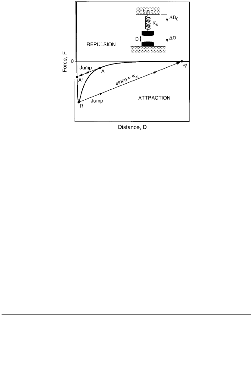
FIGURE 9.1
Schematic attractive force law between two macroscopic objects, such as two magnets, or between two
microscopic objects such as the van der Waals force between a metal tip and a surface. On lowering the base supporting
the spring, the latter will expand or contract such that at any equilibrium separation
D
the attractive force balances
the elastic spring restoring force. However, once the gradient of the attractive force between the surfaces
dF
/
dD
exceeds the gradient of the spring restoring force, defined by the spring constant
K
S
, the upper surface will jump
from
A
into contact at
A
′
(
A
for advancing). On separating the surfaces by raising the base, the two surfaces will
jump apart from
R
to
R
′
(
R
for receding). The distance
R
–
R
′
multiplied by
K
S
gives the adhesion force, i.e., the value
of
F
at
R
.

© 1999 by CRC Press LLC
apparatuses such as the surface forces apparatus (SFA) (Israelachvili, 1989, 1991) or the atomic force
microscope (AFM) (Ducker et al., 1991).
If
K
S
is the stiffness of the force-measuring spring and
∆
D
the distance the two surfaces jump apart
when they separate, then the adhesion force
F
S
is given by
(9.1)
where we note that in liquids the maximum or minimum in the force may occur at some nonzero surface
separation (see Figures 9.3 and 9.4 below).
From
F
S
one may also calculate the surface or interfacial energy
γ
. However, this depends on the
geometry of the two bodies. For a sphere of radius
R
on a flat surface, or for two crossed cylinders of
radius
R
, we have (Israelachvili, 1991)
(9.2)
while for two spheres of radii
R
1
and
R
2
(9.3)
where
γ
is in units of J/m
2
.
9.2.2 Force Law
The full force law
F
(
D
) between two surfaces, that is, the force
F
as a function of surface separation
D
,
can be measured in a number of ways. The simplest is to move the base of the spring (see Figure 9.1) by
a known amount, say,
∆
D
0
. If there is a detectable force between the two surfaces, this will cause the
force-measuring spring to deflect by, say,
∆
D
S
, while the surface separation changes by
∆
D
. These three
displacements are related by
(9.
4)
The force difference
∆
F
between the initial and final separations is given by
(9.5)
The above equations provide the basis for measuring the force difference between any two surface
separations. For example, if a particular force-measuring apparatus can measure
∆
D
0
,
∆
D
S
, and
K
S
, then
by starting at some large initial separation where the force is zero (
F
= 0) and measuring the force
difference
∆
F
between this initial or reference separation
D
and (
D
–
∆
D
), then working one’s way in
increasing increments of
∆
D
= (
∆
D
0
–
∆
D
S
), the full force law
F
(
D
) can be constructed over any desired
distance regime.
Whenever an equilibrium force law is required, it is essential to establish that the two surfaces have
stopped moving before the “equilibrium” displacements are measured. When displacements are measured
while two surfaces are still in relative motion, one also measures a viscous or frictional contribution to
the total force. Such dynamic force measurements have enabled the viscosities of liquids near surfaces
and in thin films to be accurately measured (Israelachvili, 1989).
FF K D
SS
==⋅
max
,∆
γ= πFR
s
3,
γ=
π
+
F
RR
s
3
11
12
,
∆∆∆DDD
S
==
0
.
∆∆FK D
SS
= .

© 1999 by CRC Press LLC
In practice, it is difficult to measure the forces between two perfectly flat surfaces because of the
stringent requirement of perfect alignment for making reliable measurements at the angstrom level. It
is far easier to measure the forces between curved surfaces, for example, two spheres, a sphere and a flat,
or two crossed cylinders. As an added convenience, the force
F
(
D
) measured between two curved surfaces
can be directly related to the energy per unit area
E
(
D
) between two flat surfaces at the same separation,
D
. This is given by the so-called “Derjaguin” approximation:
(9.6)
where
R
is the radius of the sphere (for a sphere and a flat) or the radii of the cylinders (for two crossed
cylinders).
9.2.3 The Surface Force Apparatus and the Atomic Force Microscope
In a typical force-measuring experiment, two or more of the above displacement parameters:
∆
D
0
,
∆
D
S
,
∆
D
, and
K
S
, are directly or indirectly measured, from which the third displacement and resulting force
law
F
(
D
) are deduced using Equations 9.4 and 9.5. For example, in SFA experiments,
∆
D
0
is changed by
expanding a piezoelectric crystal by a known amount and the resulting change in surface separation
∆
D
is measured optically, from which the spring deflection ∆D
S
is obtained. In contrast, in AFM experiments,
∆D
0
and ∆D
S
are measured using a combination of piezoelectric, optical, capacitance, or magnetic
techniques, from which the surface separation ∆D is deduced. Once a force law is established, the geometry
of the two surfaces must also be known (e.g., the radii R of the surfaces) before one can use Equation 9.6
or some other equation that enables the results to be compared with theory or with other experiments.
Israelachvili (1989, 1991), Horn (1990), and Ducker et al. (1991) have described various types of SFAs
suitable for making adhesion and force law measurements between two curved molecularly smooth
surfaces immersed in liquids or controlled vapors. The optical technique used in these measurements
employs multiple beam interference fringes which allows for surface separations D to be measured to
±1 Å. From the shapes of the interference fringes, one also obtains the radii of the surfaces, R, and any
surface deformation that arises during an interaction (Israelachvili and Adams, 1978; Chen et al., 1992).
The distance between the two surfaces can also be independently controlled to within 1 Å, and the force
sensitivity is about 10
–8
N (10
–6
g). For the typical surface radii of R ≈ 1 cm used in these experiments, γ
values can be measured to an accuracy of about ±10
–3
mJ/m
2
(±10
–3
erg/m
2
).
Various surface materials have been successfully used in SFA force measurements including mica
(Pashley, 1981, 1982, 1985), silica (Horn et al., 1989b), and sapphire (Horn et al., 1988).
It is also possible
to measure the forces between adsorbed polymer layers (Klein, 1983, 1986; Patel and Tirrell, 1989; Ploehn
and Russel, 1990), surfactant monolayers and bilayers (Israelachvili, 1987, 1991; Christenson, 1988a;
Israelachvili and McGuiggan, 1988), and metal and metal oxide layers deposited on mica (Coakley and
Tabor, 1978; Parker and Christenson, 1988; Smith et al., 1988; Homola et al., 1993; Steinberg et al., 1993).
The range of liquids and vapors that can be used is almost endless, and so far these have included aqueous
solutions, organic liquids and solvents, polymer melts, various petroleum oils and lubricant liquids, and
liquid crystals.
Recently, new friction attachments were developed suitable for use with the SFA (Homola et al., 1989;
Van Alsten and Granick, 1988, 1990b; Klein et al., 1994; Luengo et al., 1997). These attachments allow
for the two surfaces to be sheared past each other at varying sliding speeds or oscillating frequencies
while simultaneously measuring both the transverse (frictional or shear) force and the normal force or
load between them. The externally applied load, L, can be varied continuously, and both positive and
negative loads can be applied. Finally, the distance between the surfaces D, their true molecular contact
area A, their elastic (or viscoelastic or elastohydrodynamic) deformation, and their lateral motion can
all be monitored simultaneously by recording the moving interference fringe pattern using a video
camera–recorder system.
ED
FD
R
()
=
()
π2
,
© 1999 by CRC Press LLC
9.3 van der Waals and Electrostatic Forces
between Surfaces in Liquids
9.3.1 van der Waals Forces
Table 9.2 lists the van der Waals force laws for some common geometries. The van der Waals interaction
between macroscopic bodies is usually given in terms of the Hamaker constant, A, which can either be
measured or calculated in terms of the dielectric properties of the materials (Israelachvili, 1991). The
Lifshitz theory of van der Waals forces provides an accurate and simple approximate expression for the
Hamaker constant for two bodies 1 interacting across a medium 2:
(9.7)
where ε
1
, ε
2
, and n
1
, n
2
are the static dielectric constants and refractive indexes of the two phases and
where I is their ionization potential which is close to 10 eV or 2 × 10
–18
J for most materials. For
nonconducting liquids and solids interacting in vacuum or air (ε
2
= n
2
= 1), their Hamaker constants are
typically in the range (5 to 10) × 10
–20
J, rising to about 4 × 10
–19
J for metals, while for interactions in
a liquid medium, the Hamaker constants are usually about an order of magnitude smaller.
For inert nonpolar surfaces, e.g., of hydrocarbons or van der Waals solids and liquids, the Lifshitz
theory has been found to apply even at molecular contact, where it can predict the surface energies (or
tensions) of solids and liquids. Thus, for hydrocarbon surfaces the Hamaker constant is typically A = 5 ×
10
–20
J. Inserting this value into the appropriate equation for two flat surfaces (Table 9.2) and using a
“cut-off” distance of D = D
0
≈ 0.15 nm when the two surfaces are in contact, we obtain for the surface
energy γ (which is conventionally defined as half the interaction energy):
(9.8)
a value that is typical for hydrocarbon solids and liquids (for liquids, γ is sometimes referred to as the
surface tension and is expressed in units of mN/m).
TABLE 9.2 van der Waals Interaction Energy and Force Between Macroscopic Bodies
of Different Geometries
Geometry of Bodies With Surfaces D Apart
van der Waals Interaction
(D R) Energy Force
Two flat surfaces (per unit area) E = A/12pD
2
F = A/6pD
3
Sphere of radius R near flat surface E = AR/6DF = AR/6D
2
Two identical spheres of radius RE = AR/12DF = AR/12D
2
Cylinder of radius R near flat surface
(per unit length)
E = F =
Two identical parallel cylinders of radius R
(per unit length)
E = F =
Two identical cylinders of radius R crossed at 90° E = AR/6DF = AR/6D
2
AR
D12 2
32/
AR
D82
52/
AR
D24
32/
AR
D16
52/
AkT
I
nn
nn
=
−
+
+
−
()
+
()
3
4
16 2
12
12
2
1
2
2
2
2
1
2
2
2
32
εε
εε
,
γ= =
π
≈
1
2
0
2
24
30E
A
D
mJ m
2
,
© 1999 by CRC Press LLC
If the adhesion force is measured between a spherical surface of radius R = 1 cm and a flat surface
using an SFA, we expect the following value for the adhesion force (see Table 9.2):
(9.9)
Using the SFA with a spring constant of K
S
= 100 N/m, such an adhesive force will cause the two
surfaces to jump apart by ∆D = F/K
S
= 3.7 × 10
–5
m = 37 µm, which can be accurately measured (actually,
for elastic bodies that deform on coming into adhesive contact, their radius R changes during the
interaction and the measured adhesion force is 25% lower — see Equation 9.21). The above example
shows how the surface energies of solids can be directly measured with the SFA and, in principle, with
the AFM (if the geometry of the tip and surface at the contact zone can be quantified). The measured
values are generally in good agreement with calculated values based on the known surface energies γ of
the materials and, for nonpolar low-energy solids, are well accounted for by the Lifshitz theory (Israelach-
vili, 1991).
For adhesion measurements in vacuum or inert atmosphere to be meaningful, the surfaces must be
both atomically smooth and clean. This is not always easy to achieve, and for this reason only inert, low-
energy surfaces, such as hydrocarbon and certain polymeric surfaces, have had their true adhesion forces
and surface energies directly measured so far. Other smooth surfaces have also been studied, such as bare
mica, metal, metal oxide, and silica surfaces but these are high-energy surfaces, so that it is difficult to
prevent them from physisorbing a monolayer of organic matter or water from the atmosphere or from
getting an oxide monolayer chemisorbed on them, all of which affects their adhesion.
Many contaminants that physisorb onto solid surfaces from the ambient atmosphere usually dissolve
away once the surfaces are immersed in a liquid, so that the short-range forces between such surfaces
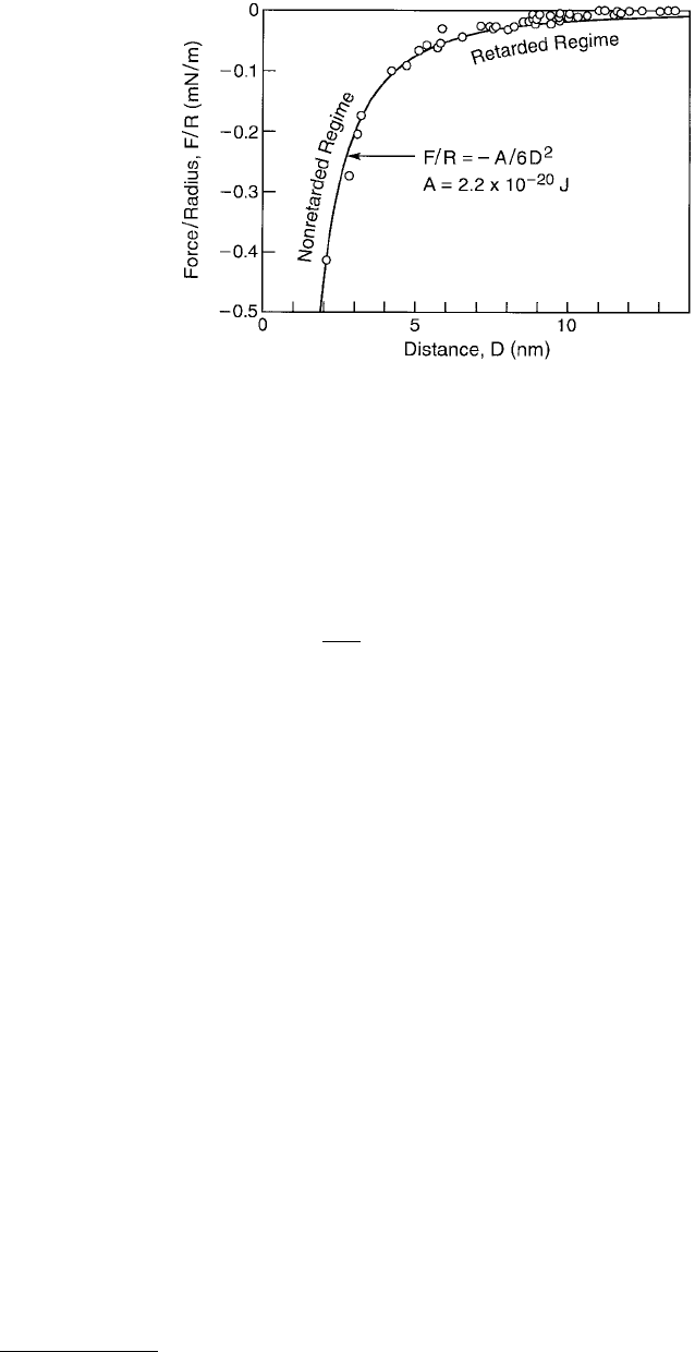
can usually be measured with great reliability. Figure 9.2 shows results of measurements of the van der
Waals forces between two crossed cylindrical mica surfaces in water and various salt solutions, showing
the good agreement obtained between experiment and theory (compare the solid curve, corresponding
to F = AR/6D
2
, where A = 2.2 × 10
–20
J is the fitted value, which is within about 15% of the theoretical
FIGURE 9.2 Attractive van der Waals force F between two curved mica surfaces of radius R ≈ 1 cm measured in
water and various aqueous electrolyte solutions. The measured nonretarded Hamaker constant is A = 2.2 × 10
–20
J.
Retardation effects are apparent at distances above 5 nm, as expected theoretically. Agreement with the continuum
Lifshitz theory of van der Waals forces is generally good at all separations down to five to ten solvent molecular
diameters (e.g., D ≈ 2 nm in water) or down to molecular contact (D = D
0
) in the absence of a solvent (in vacuum).
F
AR
D
R==π
≈×
()
−
6
4
37 10
0
2
3
γ
..N about 0.4 grams

© 1999 by CRC Press LLC
nonretarded Hamaker constant for the mica–water–mica system). Note how at larger surface separations,
above about 5 nm, the measured forces fall off faster than given by the inverse-square law. This, too, is
predicted by Lifshitz theory and is known as the “retardation effect.”
From Figure 9.2 we may conclude that at separations above about 2 nm, or 8 molecular diameters of
water, the continuum Lifshitz theory is valid. This can be expected to mean that water films as thin as
2 nm may be expected to have bulklike properties, at least as far as their interaction forces are concerned.
Similar results have been obtained with other liquids, where in general for films thicker than 5 to
10 molecular diameters their continuum properties, both as regards their interactions and other prop-
erties such as viscosity, are already manifest.
9.3.2 Electrostatic Forces
Most surfaces in contact with a highly polar liquid such as water acquire a surface charge, either by the
dissociation of ions from the surfaces into the solution or the preferential adsorption of certain ions from
the solution. The surface charge is balanced by an equal but opposite layer of oppositely charged ions
(counterions) in the solution at some small distance away from the surface. This distance is known as
the Debye length which is purely a property of the electrolyte solution. The Debye length falls with
increasing ionic strength and valency of the ions in the solution, and for aqueous electrolyte (salt)
solutions at 25°C the Debye length is
(9.10)
where the salt concentration M is in moles. The Debye length also relates the surface charge density σ
of a surface to the electrostatic surface potentials ψ
0
via the Grahame equation:
(9.11)
where the concentrations [M
1:1
] and [M
2:2
] are again in M, ψ
0
in mV, and σ in C m
–2
(1 C m
–2
corresponds
to one electronic charge per 0.16 nm
2
or 16 Å
2
). For example, for NaCl solutions, 1/κ ≈ 10 nm at 1 mM,
and 0.3 nm at 1 M. In totally pure water at pH 7, where [M
1:1
] = 10
–7
M, the Debye length is 960 nm, or
about 1 µm.
The Debye length, being a measure of the thickness of the diffuse atmosphere of counterions near a
charged surface, also determines the range of the electrostatic “double-layer” interaction between two
charged surfaces. The repulsive energy E per unit area between two similarly charged planar surfaces is
given by the following approximate expressions, known as the “weak overlap approximations”:
(9.12)
where the concentration [M
1:1
] and [M
2:2
] are again in moles.
Using the Derjaguin approximation, Equation 9.6, we may immediately write the expression for the
force F between two spheres of radius R as F = πRE, from which the interaction free energy is obtained
by a further integration as
κ
−
=
=
=
1
11
12
22
0 304
0 174
0 152
.
.
. ,
:
:
:
M
M
M
for 1:1 electrolytes such as NaCl
for 1:2 or 2:1 electrolytes such as CaCl
for 2:2 electrolytes such as MgSO
2
4
σψ
ψ
=
()
++
()
−
0 117 51 4 2
01122
25 7
12
0
. sinh . ,
::
.
MM e
E mV J m for monovalent salts
= 0.0211 M mV J m for divalent salts
-2
2:2
-2
=
[]
()
[]
[]
()
[]
−
−
0 0482 103
2 103
11
12
2
0
12
2
0
. tanh
tanh ,
:
Me
e
D
D
ψ
ψ
κ
κ

© 1999 by CRC Press LLC
(9.13)
The above approximate expressions are accurate only for surface separations beyond about one Debye
length. At smaller separations one must resort to numerical solutions of the Poisson–Boltzmann equation
to obtain the exact interaction potential for which there are no simple expressions (Hunter, 1987).
In the
limit of small D, it can be shown that the interaction energy depends on whether the surfaces remain at
constant potential ψ
0
(as assumed in the above equations) or at constant charge σ (when the repulsion
exceeds that predicted by the above equations), or somewhere in between these two limits. In the “constant
charge limit,” since the total number of counterions between the two surfaces does not change as D falls,
the number density of ions is given by 2σ/eD, so that the limiting pressure P (or force per unit area, F)
in this case is the osmotic pressure of the confined ions, given by
(9.14)
that is, as D → 0 the double-layer pressure becomes infinitely repulsive and independent of the salt
concentration. However, the van der Waals attraction, which goes as 1/D
2
between two spheres or as 1/D
3
between two planar surfaces (see Table 9.2) actually wins out over the double-layer repulsion as D → 0.
At least this is the theoretical prediction, which forms the basis of the so-called Derjaguin–Landau–Ver-
wey–Overbeek (DLVO) theory, illustrated in Figure 9.3. In practice, other forces (described below) often
come in at small separations, so that the full force law between two surfaces or colloidal particles in
solution can be more complex than might be expected from the DLVO theory.
9.4 Solvation and Structural Forces: Forces Due to Liquid
and Surface Structure
When a liquid is confined within a restricted space, for example, a very thin film between two surfaces,
it ceases to behave as a structureless continuum. Likewise, the forces between two surfaces close together
in liquids can no longer be described by simple continuum theories. Thus, at small surface separations —
below about 10 molecular diameters — the van der Waals force between two surfaces or even two solute
molecules in a liquid (solvent) is no longer a smoothly varying attraction. Instead, there now arises an
additional “solvation” force that generally oscillates with distance, varying between attraction and repul-
sion, with a periodicity equal to some mean dimension σ of the liquid molecules (Horn and Israelachvili,
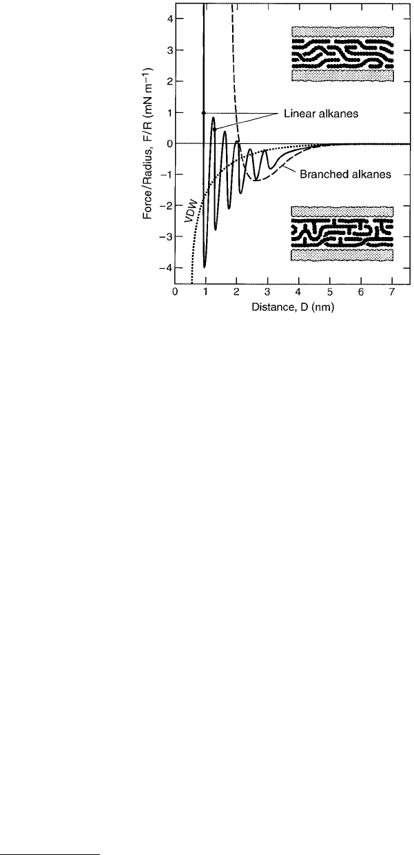
1981). Figure 9.4 shows the force law between two smooth mica surfaces across the hydrocarbon liquid
tetradecane whose inert chainlike molecules have a width of σ ≈ 0.4 nm.
The short-range oscillatory force law, varying between attraction and repulsion with a molecular-scale
periodicity, is related to the “density distribution function” and “potential of mean force” characteristic
of intermolecular interactions in liquids. These forces arise from the confining effect that two surfaces
have on the liquid molecules between them, forcing them to order into quasi-discrete layers which are
energetically or entropically favored (and correspond to the free energy minima) while fractional layers
are disfavored (energy maxima). The effect is quite general and arises with all simple liquids when they
are confined between two smooth surfaces, both flat and curved.
Oscillatory forces do not require that there be any attractive liquid–liquid or liquid–wall interaction.
All one needs is two hard walls confining molecules whose shapes are not too irregular and that are free
to exchange with molecules in the bulk liquid reservoir. In the absence of any attractive forces between
the molecules, the bulk liquid density may be maintained by an external hydrostatic pressure. In real
liquids, attractive van der Waals forces play the role of the external pressure, but the oscillatory forces
are much the same.
Oscillatory forces are now well understood theoretically, at least for simple liquids, and a number of
theoretical studies and computer simulations of various confined liquids, including water, which interact
WR e
D
=×
()
[]
−−
4 61 10 103
11 2
0
. tanh .ψ
κ
mV J for 1:1 electrolytes
F kT kT zeD D=× =
−
ion number density for2
1
σκ ,
© 1999 by CRC Press LLC
via some form of the Lennard–Jones potentials have invariably led to an oscillatory solvation force at
surface separations below a few molecular diameters (Snook and van Megan, 1979, 1980, 1981; van
Megan and Snook, 1979, 1981; Kjellander and Marcelja, 1985a,b; Tarazona and Vincente, 1985; Hend-
erson and Lozada-Cassou, 1986; Evans and Parry, 1990).
In a first approximation the oscillatory force laws may be described by an exponentially decaying
cosine function of the form
(9.15)
where both theory and experiments show that the oscillatory period and the characteristic decay length
of the envelope are close to σ (Tarazona and Vincent, 1985).
It is important to note that once the solvation zones of two surfaces overlap, the mean liquid density
in the gap is no longer the same as that of the bulk liquid. And since the van der Waals interaction
depends on the optical properties of the liquid, which in turn depend on the density, one can see why
the van der Waals and oscillatory solvation forces are not strictly additive. Indeed, it is more correct to
think of the solvation force as the van der Waals force at small separations with the molecular properties
and density variations of the medium taken into account.
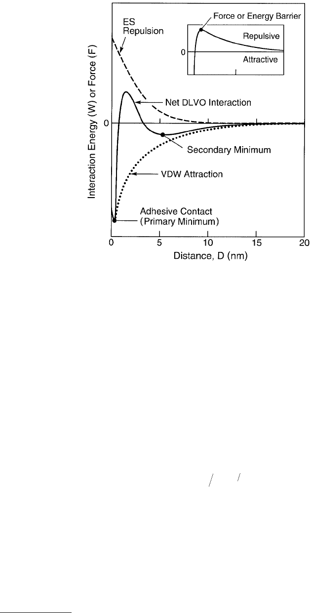
FIGURE 9.3 Classical DLVO interaction potential energy as a function of surface separation between two flat
surfaces interacting in an aqueous electrolyte (salt) solution via an attractive van der Waals (VDW) force and a
repulsive screened electrostatic (ES) double-layer force. The double-layer potential (or force) is repulsive and roughly
exponential in distance dependence. The attractive van der Waals potential has an inverse power law distance
dependence (see Table 9.2) and it therefore “wins out” at small separations, resulting in strong adhesion in a “primary
minimum”. The inset shows a typical interaction potential between surfaces of high surface charge density in dilute
electrolyte solution. All curves are schematic. Note that the force F between two curved surfaces of radius R is directly
proportional to the interaction energy E or W between two flat surfaces according to the Derjaguin approximation,
Equation 9.6.
EE D e
D
≈π
()
−
0
2cos ,σ
σ
© 1999 by CRC Press LLC
It is also important to appreciate that solvation forces do not arise simply because liquid molecules
tend to structure into semiordered layers at surfaces. They arise because of the disruption or change of
this ordering during the approach of a second surface. If there were no change, there would be no solvation
force. The two effects are, of course, related: the greater the tendency toward structuring at an isolated
surface, the greater the solvation force between two such surfaces, but there is a real distinction between
the two phenomena that should always be borne in mind.
Concerning the adhesion energy or force of two smooth surfaces in simple liquids, a glance at Figure 9.4
and Equation 9.15 shows that oscillatory forces lead to multivalued, or “quantized,” adhesion values,
depending on which energy minimum two surfaces are being separated from. For an interaction energy
that varies as described by Equation 9.15, the quantized adhesion energies will be E
0
at D = 0 (primary
minimum), E
0
/e at D = σ (second minimum), E
0
/e
2
at D = 2σ, etc. Such multivalued adhesion forces
have been observed in a number of systems, including the interactions of fibers. Most interesting, the
depth of the potential energy well at contact (–E
0
at D = 0) is generally deeper but of similar magnitude
to the value expected from the continuum Lifshitz theory of van der Waals forces (at a cutoff separation
of D
0
≈ 0.15 – 0.20 nm), even though the continuum theory fails to describe the shape of the force law
at intermediate separations.
There is a rapidly growing literature on experimental measurements and other phenomena associated
with short-range oscillatory solvation forces. The simplest systems so far investigated have involved
measurements of these forces between molecularly smooth surfaces in organic liquids. Subsequent mea-
surements of oscillatory forces between different surfaces across both aqueous and nonaqueous liquids
have revealed their subtle nature and richness of properties (Christenson, 1985, 1988a; Christenson and
Horn, 1985; Israelachvili, 1987; Israelachvili and McGuiggan, 1988), for example, their great sensitivity
FIGURE 9.4 Solid curve: Forces between two mica surfaces across saturated linear-chain alkanes such as n-tetrade-
cane (Christenson et al., 1987; Horn and Israelachvili, 1988; Israelachvili and Kott, 1988; Horn et al., 1989a). The
0.4-nm periodicity of the oscillations indicates that the molecules align with their long axis preferentially parallel to
the surfaces, as shown schematically in the upper insert. The theoretical continuum van der Waals force is shown
by the dotted line. Dashed line: Smooth, nonoscillatory force law exhibited by irregularly shaped alkanes, such as
branched isoparaffins, that cannot order into well-defined layers (lower insert) (Christenson et al., 1987). Similar
nonoscillatory forces are also observed between rough surfaces, even when these interact across a saturated linear
chain liquid. This is because the irregularly shaped surfaces (rather than the liquid) now prevent the liquid molecules
from ordering in the gap.
© 1999 by CRC Press LLC
to the shape and rigidity of the solvent molecules, to the presence of other components, and to the
structure of the confining surfaces. In particular, the oscillations can be smeared out if the molecules are
irregularly shaped (e.g., branched) and therefore unable to pack into ordered layers, or when the inter-
acting surfaces are rough or fluidlike (e.g., surfactant micelles or lipid bilayers in water) even at the
angstrom level (Gee and Israelachvili, 1990).
9.4.1 Effects of Surface Structure
It has recently been appreciated that the structure of the confining surfaces is just as important as the
nature of the liquid for determining the solvation forces (Rhykerd et al., 1987; Schoen et al., 1987, 1989;
Landman et al., 1990; Thompson and Robbins, 1990; Han et al., 1993).
Between two surfaces that are
completely smooth or “unstructured,” the liquid molecules will be induced to order into layers, but there
will be no lateral ordering within the layers. In other words, there will be positional ordering normal but
not parallel to the surfaces. However, if the surfaces have a crystalline (periodic) lattice, this will induce
ordering parallel to the surfaces as well, and the oscillatory force then also depends on the structure of
the surface lattices. Further, if the two lattices have different dimensions (“mismatched” or “incommen-
surate” lattices), or if the lattices are similar but are not in register but are at some “twist angle” relative
to each other, the oscillatory force law is further modified.
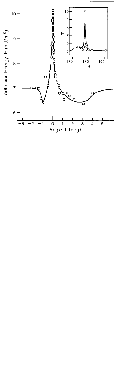
McGuiggan and Israelachvili (1990) measured the adhesion forces and interaction potentials between
two mica surfaces as a function of the orientation (twist angle) of their surface lattices. The forces were
measured in air, in water, and in an aqueous salt solution where oscillatory structural forces were present.
In air, the adhesion was found to be relatively independent of the twist angle θ due to the adsorption of
a 0.4-nm-thick amorphous layer of organics and water at the interface. The adhesion in water is shown
in Figure 9.5. Apart from a relatively angle-independent “baseline” adhesion, sharp adhesion peaks
(energy minima) occurred at θ = 0°,
±60°, ±120°, and 180°, corresponding to the “coincidence” angles
of the surface lattices. As little as
±1° away from these peak, the energy decreases by 50%. In aqueous
salt (KCl) solution, due to potassium ion adsorption the water between the surfaces becomes ordered,
resulting in an oscillatory force profile where the adhesive minima occur at discrete separations of about
0.25 nm, corresponding to integral numbers of water layers. The whole interaction potential was now
found to depend on orientation of the surface lattices, and the effect extended at least four molecular layers.
Although oscillatory forces are predicted from Monte Carlo and molecular dynamic simulations, no theory
has yet taken into account the effect of surface structure, or atomic “corrugations,” on these forces, nor any
FIGURE 9.5 Adhesion energy for two mica surfaces
in a primary minimum contact in water as a function
of the mismatch angle θ about θ = 0° between the two
contacting surface lattices (McGuiggan and Israelach-
vili, 1990). Similar peaks are obtained at the other coin-
cidence angles: θ = ±60°, ±120°, and 180° (inset).