Bowker M., Davies P.R. (Eds.) Scanning Tunneling Microscopy in Surface Science, Nanoscience and Catalysis
Подождите немного. Документ загружается.

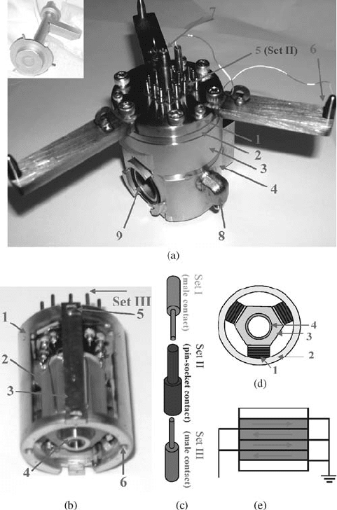
Figure 7.3 High-pressure reactor and
STM body. (a) A view of the whole reactor:
(1) cell lid, (2) cell neck, (3) middle stage,
(4) bottom stage, (5) pin-socket contacts
for wiring of STM body at the interface of
high-vacuum and high-pressure environment,
(6) a pin on the lever of the cell lid for
mounting, (7) Swagelok fitting welded on the
tube of the cell lid for gas introduction,
(8) Swagelok fitting welded on the button
stage of reactor for gas exit, (9) port of
reactor for sample and tip transfer. (b) Side
view of the STM body: (1) Wall of STM body
coated with a layer of gold, (2) hexagonal
sapphire, (3) CuBe spring plates, (4) receiver
of tip holder, (5) screw to adjust the pressure
applied to hexagonal sapphire, (6) hole to
assemble sample stage to STM body. (c)
Scheme of pin-socket alignment for wiring. Set
III is the contacts glued to the holes on top of
STM body; Set II is the contacts glued to the
holes on top of cell lid of the reactor; Set I is the
contacts glued to wires from docking scaffold.
(d) Scheme showing the assembly of three
packs of shear piezoelectric plates between the
hexagonal sapphire and the wall of the STM
body and the assembly of the scanning tube: (1)
a set of piezoelectric plates, (2) wall of STM
body, (3) hexagonalsapphire,(4) scanningtube.
(e) Scheme showing how the four shear piezo-
electric plates of one set work for coarse
approach.
194
j
7 Surface Mobility of Atoms and Molecules Studied with High-Pressure STM
a sample stage assembled at the end of the STM body, and wire connections to
these parts. The coarse approach is carried out by six sets of shear piezoelectric plates
(three of them are schematically shown in a bottom view of STM body in Figure 7.3d)
located between a hexagonal sapphire (Figure 7.3b2) and the wall of the STM body.
One side of each shear piezoelectric set is glued to the internal wall of the STM body
through an alumina plate for thermal isolation while the other side is glued to another
alumina plate that contacts the surface of the hexagonal sapphire (Figure 7.3d and e).
By applying negative or positive voltages to the first/third and the second/fourth
piezoelectric plates, the lateral force moves the hexagonal sapphire forward and
backward (Figure 7.3e). A single piezoelectric scanning tube is glued to an alumina
disk that is in turn glued to one end of the hexagonal sapphire. Five Kapton wires are
glued to the five components ( þx, x, þy, y, z) of the scanning tube through holes
on the alumina disk. Another alumina disk is glued to the other end of the scanning
tube onto which a bowl-shaped tip receiver is glued (Figure 7.3b4). The central part
of this tip receiver is a SmCo magnet. The tip change mechanism is described below.
A flexible coaxial wire is glued to this tip receiver for transmitting the tunneling
current.
A sample assembly stage is screwed to the end of the STM body (Figure 7.3b6),
which is thermally and electrically insulated from it by three precisely aligned
sapphire balls and insulating washers. For sample transfer and tip change, a port
is opened on the wall of the bottom stage of the high-pressure reactor (Figure 7.3a9).
A bayonet seal (inset of Figure 7.3a) was fabricated to seal the port on the reactor. This
sealing keeps the pressure in vacuum chamber lower than 5 10
7
Torr when the
high-pressure reactor is filled with 1000 Torr N
2
. The naturally leaked gases from the
sealing interface between different sections of the reactor can be analyzed in situ
with a mass spectrometer during reaction.
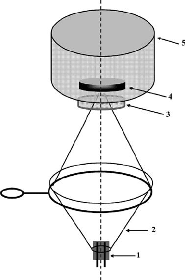
The in situ sample heating during reaction is carried out by a light source outside
the high-pressure reactor to avoid heating elements in the high-pressure environ-
ment. It consists of a halogen lamp with an elliptical reflector that focuses the
radiation onto the sample through a sapphire window welded at the bottom of the
reactor (Figure 7.4). The distance between the lamp and the reactor can be adjusted to
focus the light on the back of the sample for efficient heating. The heating rate can be
controlled by adjusting the power supplied to the lamp. A K-type thermocouple was
spot-welded to the sample stage for both sample bias and temperature measure-
ments. Another thermocouple was attached to the STM body to monitor the
temperature of the shear piezoelectric plates during sample heating. Thus, thermal
diffusion and possible increases in the temperature of the STM body can be
simultaneously monitored when the sample in the high-pressure reactor is heated.
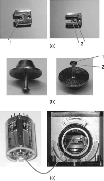
Replacement of the STM tip is accomplished using a magnetic tip exchanger with
the same geometry as the sample holder (Figure 7.5a) and a tip holder (Figure 7.5b).
The tip exchanger can be easily transferred to and from the high-pressure reactor
(Figure 7.5c), the storage disk, and the load-lock system.
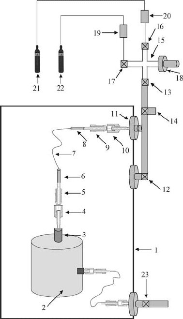
Figure 7.6 schematically shows the setup of gas introduction for the high-pressure
reactor. For gas introduction, the male part of a Swagelok fitting (4 in Figure 7.6)
is welded on a 1/8 in. tube of the cell lid (3 in Figure 7.6). A 1/32 in. PEEK tube
7.3 High-Pressure STM Technique and Instrumentation
j
195
(7 in Figure 7.6) capable of supporting high pressure was glued to a 1/16 in. stainless
steel tube (6 in Figure 7.6) assembled into a female part of the Swagelok fitting (5 in
Figure 7.6). Another end of the PEEK tube is also glued and assembled to another
Swagelok fitting welded to a hole in a double-sided CF flange. This design isolates the
reactant gases in the high-pressure reactor from the vacuum environment of the STM
chamber. The high-pressure gases in the reactor can be pumped down by a turbo
molecular pump to obtain a UHV environment after completion of a high-pressure
experiment,thereforequicklyrestoringa UHVenvironment.Thus,thishigh-pressure
reaction system can work under both UHV and high pressure, offering the capability
of studying catalysts over the entire pressure range from 1 10
10
to 5000 Torr.
In addition, the reactions can be carried out using batch or flow reactor mode.
Atomically resolved images of inert HOPG under 700 Torr N
2
and of hex-Pt(1 0 0)
prepared in UHV can be routinely obtained with this homebuilt high-pressure high-
temperature STM reactor/UHV system.
Figure 7.4 STM chamber in situ sample heating system.
(1) Halogen lamp, (2) elliptical reflector, (3) sapphire window
welded at the center of the bottom of the high-pressure reactor,
(4) the assembled sample, (5) high-pressure reactor. Turquoise
dashed line shows the alignment of light beam and sample center.
196
j
7 Surface Mobility of Atoms and Molecules Studied with High-Pressure STM
7.4
Mobility and Flexibility of Catalyst Surfaces at High-Pressure High-Temperature
Reaction Conditions
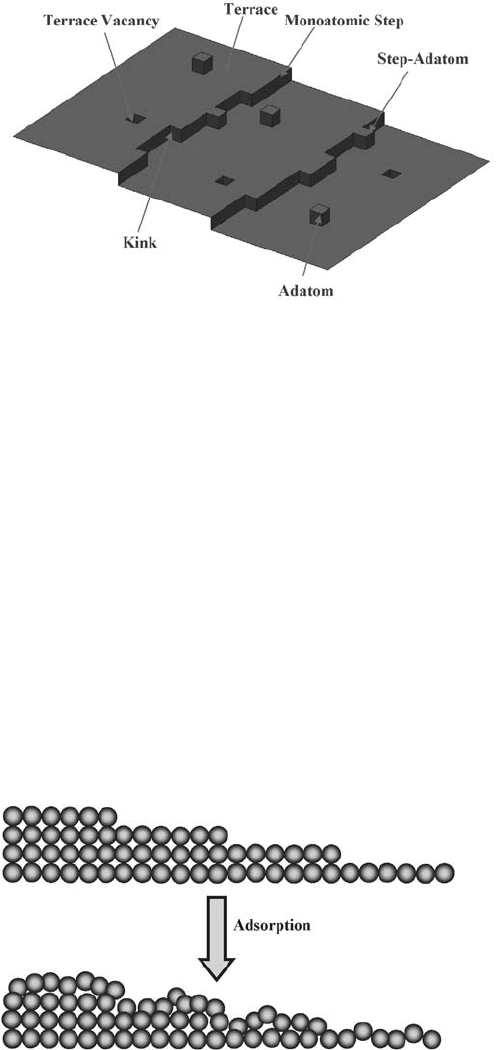
The exploration of the surface of single-crystal model catalysts has a long history.
Electron microscopy and field-emission microscopy developed in the 1950s revealed
the existence of surface steps and kinks, which led to the development of the
heterogeneous rigid surface model (Figure 7.7) proposed in 1960s [21]. In this
model, a surface is heterogeneous and the atoms of the surface layer are arranged at
the exactly same sites as those in the bulk. That is, the location of surface atoms can be
exactly provided by the structural parameters of a bulk layer. This model ignored
Figure 7.5 Parts used for a convenient tip
exchange. (a) Tip exchanger: (1) the central
slot that has a size between the stopping
disk and outer diameter of the tube of the
tip holder, (2) magnets. (b) Tip holder with
an empty tube for placing a tip: (1) empty
tube for placing a STM tip, (2) stopping disk.
(c) Magnetic bowl glued at the end of the
scanning tube. The arrow shows the hidden
bowl at the end of the scanning tube.
7.4 Mobility and Flexibility of Catalyst Surfaces
j
197
the surface effects of relaxation and reconstruction. But it was reasonable to some
extent at that time because it could rationalize the kinetics of crystal growth and the
site-dependent performance of chemisorption and charge distribution. The new
results obtained with the surface analytic techniques developed in 1980s showed that
this heterogeneous rigid model was not correct. We put forward the concept of the
flexible surface in 1991 [13, 22]. One structural evidence of the flexibility of surfaces is
the inward relaxation of the first layer of a clean metal surface to produce a short
Figure 7.6 Scheme showing the introduction of
high-pressure reactant gases to reactor when
the reactor is under UHV environment of the
STM chamber. (1) STM chamber, (2) high-
pressure reactor, (3) stainless steel tube
(ID ¼1/8 in.), (4) and (10) male part of a
Swagelok fitting, (5) and (9) female part of a
Swagelok fitting, (6) and (8) silica-coated
stainless steel tube (ID ¼1/16 in.), (7) PEEK
tubing (OD ¼1/16 in., ID ¼1/32 in.), (11)
double-sided CF flange, (12) and (13) angle
valves, (14) angle valve for pumping reactant
gases after completion of a batch mode high-
pressure experiments, (15) vessel for mixing
different reactant gases, (16) and (17) variable
leak valves, (18) Baratron capacitance mano-
meter for pressure measurements, (19) and
(20) gas filters, (21) and (22) gas cylinders,
and (23) angle valve.
198
j
7 Surface Mobility of Atoms and Molecules Studied with High-Pressure STM
interlayer distance in contrast to the distance between two adjacent bulk layers
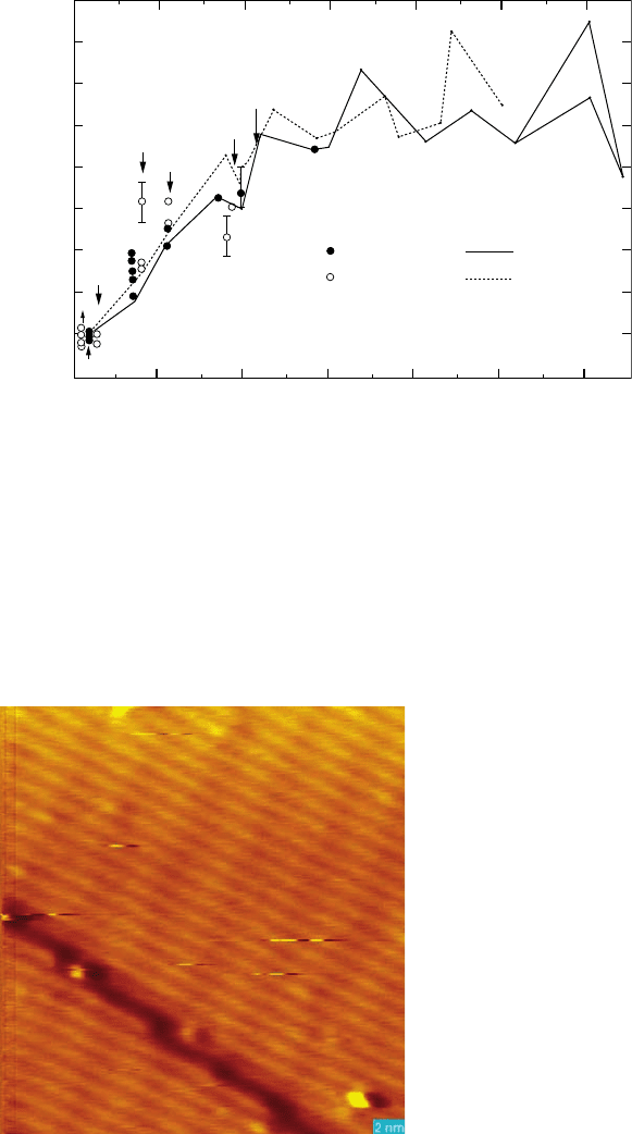
(Figure 7.8). In fact, extensive studies of surface structure confirm the general
phenomena of surface relaxation as shown in Figure 7.9. Moreover, we discovered
two rules that the flexibility of metal surfaces generally follow [22]: (a) the closer
packed and lower Miller index surfaces on which atoms have large coordination are
generally less flexible and (b) , more importantly, the flexibility of chemisorbed
surfaces results in possible surface reactions induced by several factors, including
adsorption and thermal-induced restructuring. This model gave a clearer picture of
the catalyst surface [13, 22].
The proposed flexibility of the surface on the basis of vacuum surface science
approach is definitely applicable to the catalyst surface under an environment of
high pressure of reactive gases. As mentioned above, entropy could significantly
contribute to the surface structure and flexibility at high-pressure conditions. Our
recent studies showed that the surface mobility of catalyst surfaces is significantly
increased at high pressures. Thus, catalyst surfaces under high pressures of reactant
gases could be considered as mobile surfaces in some cases. Here, we use the
Figure 7.7 Heterogeneous rigid surface model.
Figure 7.8 Restructuring of surface atoms at step sites of a clean surface.
7.4 Mobility and Flexibility of Catalyst Surfaces
j
199
pressure-dependent adsorption and surface structure of hex-Pt(1 0 0) under an
environment of CO as an example to illustrate the mobility of the metal atoms of
catalyst surfaces. Figure 7.10 is one image of the clean hex-Pt(1 0 0) surface prepared
in UHV. The surface structures and the nanoclusters formed at different pressures
of CO are shown in Figures 7.11 to 7.13. Overall, the surface of hex-Pt(1 0 0)
Figure 7.10 STM image of a clean hex-Pt(1 0 0) surface.
211
211
111
111
310
bcc
bcc
fcc fcc
expt. theory
1 2 3 4 5 6 7
ROUGHNESS
-40
-35
-30
-25
-20
-15
-10
-5
0
+5
Δ(d
z
)
12
/Δ(d
z
)
bulk
(%)
}}
110
511
221
210
332
321
321
110
221
322
320
510
311
332
320
322
331
410
411
210
001
001
331
311
Figure 7.9 Experimental and theoretical first-layer relaxation
(in percentage) as a function of roughness (¼ l/packing density)
for several bcc and fcc surfaces.
200
j
7 Surface Mobility of Atoms and Molecules Studied with High-Pressure STM
undergoes a phase change and forms nanoclusters under certain pressures of CO at
room temperature. More importantly, the size and shape of the nanoclusters
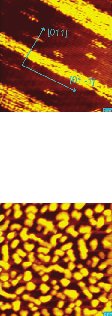
formed are pressure-dependent. At a low pressure of 5 10
9
Torr (Figure 7.11),
a portion of the surface is preferentially lifted along the [0 1 1] direction. However,
when a clean hex-Pt(1 0 0) surface is exposed to approximately 10
5
Torr CO, islands
with a rectangular shape and a size of 1.5–4.0 nm are formed (Figure 7.12). There is
no preferential growth along any direction. At a high pressure of 1 Torr CO,
Figure 7.12 STM image of a lifted Pt(1 0 0) surface at a condition of 5 10
7
Torr CO.
Figure 7.11 STM image of a lifted Pt(1 0 0) surface at a condition of 5 10
9
Torr CO.
7.4 Mobility and Flexibility of Catalyst Surfaces
j
201
nanoclusters with a round or ellipse shape are formed on the whole surface.
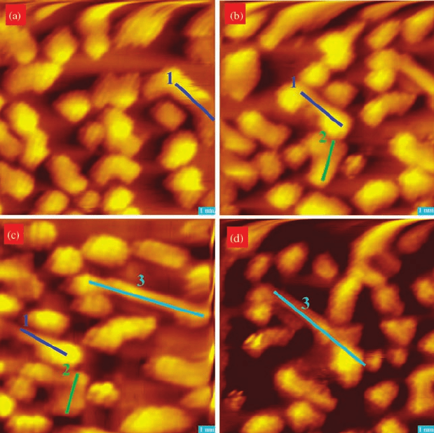
Figure 7.14 shows the evolution of the surface structure formed at approximately
5 10
7
Torr CO in a time interval of 28 min. The landmarks in Figure 7.14 are
used to identify the same location between two adjacent images since thermal drift
is present at 300 K. This figure clearly shows the shape and size of the formed
nanoclusters. During this time interval, the shape of islands changes quickly and a
portion of the atoms in adjacent nanoclusters move together and then form new
nanoclusters, indicating significant surface mobility for the lifted Pt atoms at this
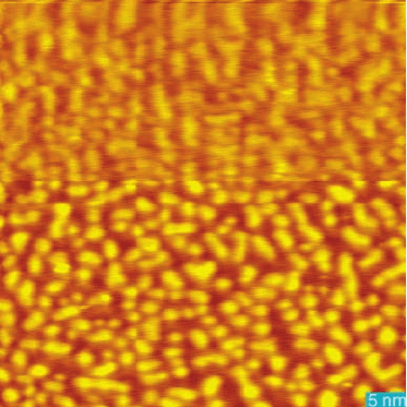
pressure. In fact, under 1 Torr CO, clean hex-Pt(1 0 0) is dramatically roughened and
forms highly dense nanoclusters with a size of 1–3 nm on the whole surface
(Figure 7.13). It suggests that a dramatic restructuring of the catalyst surface is
induced by the presence of a high pressure of reactant gas. Notably, no atomically
resolved image can be obtained from the catalyst surface in an environment with
CO pressure higher than 10
4
Torr, whereas atomically resolved images can be
obtained at a pressure of 10
10
–10
5
Torr CO. This suggests higher mobility of Pt
atoms on the catalyst surface under higher pressure of CO.
Temperature is another factor in surface mobility as evidenced by the aggregation
of surface islands when the lifted islands are heated from the original 25–150
C
(Figure 7.15). Figure 7.15a is the STM of hex-Pt(1 0 0) exposed to 1 Torr CO at room
temperature. Clearly, the surface formed at this pressure of CO consists of Pt
nanoclusters with a size of 2–3 nm. When this surface is heated in situ to 150
C,
the lifted surface structure significantly changes (Figure 7.15b). The clusters formed
at room temperature largely aggregate together at 150
C, forming clusters with a size
of 3–7 nm. This aggregation illustrates again the high flexibility and mobility of a
catalyst surface.
Surface mobility and flexibility were evidenced by dramatic reconstruction of the
Pt(1 0 0) surface upon annealing this surface at 150
C for 4–5 h in 1–1.6 atm of
Figure 7.13 STM image of Pt(1 0 0) surface at a condition of 1 Torr CO.
202
j
7 Surface Mobility of Atoms and Molecules Studied with High-Pressure STM
reactant gases (H
2
,O
2
, or CO) [13, 23]. After exposing a clean Pt(1 1 0) surface to
1.6 atm H
2
and annealing at 150
C for 5 h in this hydrogen environment, the
surface is dominated by parallel rows that are the formed (1 n) missing rows
randomly nested (Figure 7.16a). This clearly demonstrates reconstruction of a
catalyst surface induced by a reactant gas at high temperature and high pressure.
Compared to the restructuring driven by hydrogen, oxygen induces the faceting of
the Pt(1 1 0) surface. After heating in 1 atm O
2
for 5 h, this catalyst surface consists
of microfaceted (1 1 1) with a width of 30–60 Å separated by steps (Figure 7.16b).
The reconstruction of Pt(1 1 0) into numerous microfaceted Pt(1 1 1) surfaces
could be driven by selective adsorption of oxygen atom on face-centered cubic
threefold hollow sites [24]. Thus, the transformation from Pt(1 1 0) to small Pt(1 1 1)
surfaces is definitely energetically favorable. When a clean Pt(1 1 0) surface is
Figure 7.14 STM images of a lifted Pt(1 0 0)
surface at condition of 5 10
7
Torr CO:
(a) t ¼t
0
min, (b) t ¼t
0
þ 10 min, (c) t ¼t
0
þ
19 min, and (d) t ¼t
0
þ 28 min. All the images
have the same size of 14.1 nm 14.1 nm. They
were obtained with the same tunneling
condition and scanning speed. Landmarks 1, 2,
and 3 represent the same cluster between
(a) and (b), between (b) and (c), and between
(c) and (d), respectively.
7.4 Mobility and Flexibility of Catalyst Surfaces
j
203