Bowker M., Davies P.R. (Eds.) Scanning Tunneling Microscopy in Surface Science, Nanoscience and Catalysis
Подождите немного. Документ загружается.

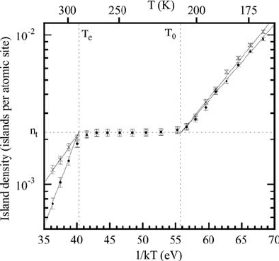
barrier may just be sufficient to control a growth process has been shown in several
cases [26, 27]. Indeed, this leads to a template-controlled growth without specific
interaction but by spatially confining the movement of the deposited particles. The
nucleation is then homogeneous but controlled by the template. This approach is
quite similar to the one used in lithography where the spatial confinement is provided
by the lithographically produced pattern on the surface. Since surface diffusion in
this case is the crucial parameter, the process will be subject to the same limitations in
terms of temperature as in the case of template-controlled heterogeneous nucleation.
Before we discuss the template-controlled growth of model catalysts in more detail,
we will have to consider a few aspects of STM imaging of these systems. This will be
crucial for the characterization of the model catalyst surfaces.
2.3
STM Imaging of Oxide Films
Even though scanning tunneling microscopy is nowadays a standard tool for surface
characterization, special care has to be taken when using it for the investigation of
thin oxide films. On clean metal surfaces, a simple metal–vacuum–metal tunneling
gap is usually found [28]. In this case, the tunneling current can be to a first
approximation described by the Tersoff–Hamann model [29], which postulates that
the main contribution to the tunneling current is due to electrons coming from the
Fermi edge. If we introduce a thin oxide film, the tunneling gap can be characterized
by a metal–oxide–vacuum–metal junction (Figure 2.5). As a consequence, the band
structure of the oxide film – in particular, the gap between the valence band (VB) and
Figure 2.4 Evolution of the island density with growth
temperature for Au/N/Cu(1 0 0). (Reproduced with permission
from Ref. [24].)
34
j
2 The Template Route to Nanostructured Model Catalysts
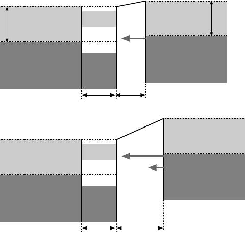
the conduction band (CB) – will play a crucial role in the tunneling process. If we
disregard local effects – such as a local variation of the barrier height – and take only
the average electronic structure of the film into account, we can distinguish two
limiting cases. For small bias voltages, the oxide film will only weakly perturb the
tunneling process. The current passes through the oxide film because no states for
the tunneling electrons are available (Figure 2.5a). It will thus act much like an
additional vacuum barrier. As a consequence, the distance from the tip to the sample
will be the sum of the film thickness d
f
and the distance between tip and film d
g
. This
does not necessarily imply that the oxide film is invisible in STM. If the lateral
structure of the oxide film is not homogeneous, the tunneling barrier will change as
a function of the lateral position of the tip and consequently the z-position of the tip
will also change, which will result in a contrast in the STM images. If, at small bias
voltage, the tunneling current is increased, the tip will touch and eventually penetrate
the film, leading to a direct overlap of the electronic states of the tip and the sample.
This will cause variations in the tunneling current as a function of the lateral tip
position, which can – in favorable cases – be used to image the surface of the oxide
film with atomic resolution [30]. Since at moderate tunneling currents (<1 nA) the
film behaves like an additional vacuum barrier, it is possible to image the substrate
tipsubstrate oxide
E
F
E
F
E
F
E
F
VB
VB
CB
CB
d
g
d
f
d
f
d
g
’
E
Vac
φ
s
φ
t
(a)
(b)
Figure 2.5 Schematic representation of the gap of a metal-
oxide–vacuum–metal tunneling junction in the case of a
low (a) and a high (b) sample bias voltage.
2.3 STM Imaging of Oxide Films
j
35
surface with atomic resolution through the oxide film with STM [31]. This can be very
helpful for the analysis of the structural relation (commensurability) of oxide film and
substrate.
In the case of the high bias voltages – depending on the sign of the bias voltage –
either the conduction band or the valence band of the oxide will participate in the
tunneling process (Figure 2.5b), and it is expected that the topography of the film in
the STM images is dramatically changed compared to the case of low bias voltages.
At positive sample bias, the main contribution to the tunneling current stems from
electrons tunneling into the conduction band of the oxide film, from which they are
further transported into the substrate. If the film is sufficiently thin, that is, thinner
than the mean free path of electrons (10 nm), a charging of the oxide film due to the
electron current is not expected [32]. It should also be mentioned that, as shown in
Figure 2.5, to a first approximation no bias voltage drop is encountered in the film
if its thickness is only around 0.5 nm.
The significant differences in the tunneling process at low and high bias voltage
will result in a strong bias dependence of the apparent topography of the oxide film.
Such a bias-dependent tunneling for thin Al
2
O
3
islands on NiAl(1 1 0) was first
observed by Bertrams et al. [33]. In this case, the islands were hardly visible at a
sample bias voltage of þ0.4 V, which corresponded to an energy in the bandgap of
the alumina islands. At a bias of þ4 V, however, the electrons tunnel into the
conduction band of the Al
2
O
3
islands and these are imaged with an apparent height
of 0.3 nm. For the similar system of Al
2
O
3
islands on Ni
3
Al(1 1 1), a systematic study
of the apparent height of the islands as a function of the bias voltage allowed the
estimation of the energetic position of the bottom of the Al
2
O
3
conduction band [34].
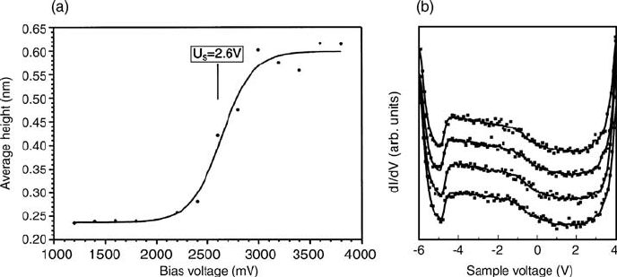
As can be seen in Figure 2.6a, the measured apparent height of the Al
2
O
3
islands
rapidly increases in the bias voltage ranging from 2.1 to 3.0 V from a value of 0.25 to
0.6 nm, which is close to the actual thickness of 0.5 nm [35]. This increase is due to
Figure 2.6 (a) Variation in the apparent height of alumina islands
on Ni
3
Al(1 1 1) as a function of sample bias voltage [34].
(b) STS dI/dV spectra taken at different points of the alumina
film surface [36].
36
j
2 The Template Route to Nanostructured Model Catalysts
the lowered tunneling resistance caused by the participation of the conduction band
of the oxide in the tunneling process. This situation is similar to the one shown in
Figure 2.5b. The determination of the band edge using this method is, however, not
very precise and based on the average properties (e.g., average height) of the islands.
However, it provides a first indication of the variations in the apparent topography of
alumina films as a function of the bias voltage encountered in STM. Furthermore,
a combination of measurements like the one shown in Figure 2.6a with UPS valence
band spectra of the respective oxide film provides a rough value of the bandgap of the
film [34]. The bandgap of the oxide film can be determined using tunneling
spectroscopy, which is shown in Figure 2.6b. These dI/dV spectra clearly show the
top of the valence band at a negative sample bias of about 5 V and the bottom of
conduction band at roughly þ3 V [36] indicating a bandgap of approximately 8 eV.
This variation in the electronic structure of the tunneling gap is reflected in the
pronounced variation in the apparent topography of Al
2
O
3
films on Ni
3
Al(1 1 1) as
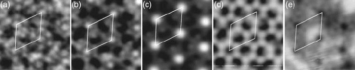
a function of bias voltage (Figure 2.7). Here, two effects are clearly visible: First, a
contrast reversal between images (c) and (d) can be seen. The formerly hexagonal
arrangement of bright dots (2.0 V) is imaged as holes at a bias voltage of 3.2 V.
This important bias dependence of the apparent topography of insulating films
has also been found in several other cases, for example, CaF
2
/Si(1 1 1) [32], CoO/
Ag(0 0 1) [37, 38], NiO/Ag(0 0 1) [39], and ZrO
2
/Pt(1 1 1) and can be attributed to the
band structure and more precisely to the bandgap of the insulating films. Second,
the apparent corrugation of the film changes drastically. For a low bias voltage of 0.5 V,
a corrugation on the order of only 0.02 nm is found, which roughly corresponds to
the corrugation found on metal surfaces, whereas at higher bias a corrugation of up to
0.2 nm is visible (Figure 2.8). It is obvious that the sharp increase in the measured
corrugation takes place in the same energy interval where the increase in the average
island height has been found for this type of oxide film (Figure 2.6a). It must,
therefore, be correlated with the electronic structure of the film in the region close to
the bottom of the conduction band.
Again a closer look at the STS spectra shown in Figure 2.9 reveals that the dots are,
indeed, closely related to the electronic structure of the film. They appear in an energy
range between 2.0 and 2.8 V, where a localized electronic state in the bandgap can be
found at the corners of the unit cell (points labeled A). This state, which is found
Figure 2.7 STM images of an alumina film on Ni
3
Al(1 1 1) at
different sample bias voltages. (a) U
b
¼0.5 V, (b) 1.5 V, (c) 2.0 V,
(d) 3.2 V, and (e) 4.2 V. The unit cell of the dot structure is marked
in the images.
2.3 STM Imaging of Oxide Films
j
37
0.4
0.3
0.2
0.1
0.0
height [nm]
1086420
distance [nm]
U
T
= +0.5 V
U
T
= +1.5 V
U
T
= +2.0 V
U
T
= +3.2 V
Figure 2.8 Line profiles of the alumina film on Ni
3
Al(1 1 1) for different sample bias voltages [36].
Figure 2.9 (a) STM image of Al
2
O
3
/Ni
3
Al(1 1 1). The
unit cell of the dot structure is shown as dashed line.
(b) STS spectra taken at the points indicated in the
STM image. The feedback loop was opened at a bias
voltage of þ3.5 and þ3.0 V (inset of b).
38
j
2 The Template Route to Nanostructured Model Catalysts
only at the corners of the unit cell, increases the tunneling probability at these
locations in the respective bias voltage range resulting in the observed contrast (see
Figure 2.7). STS spectra taken at the points labeled B do not show this state. It is,
thus, clearly localized at the corners of the unit cell.
This particular example shows that special care has to be taken when the
topography of thin oxide layers on metallic substrates is measured by STM. Electronic
effects at or near the band edges can dramatically influence the tunneling proba-
bilities and, thus, lead to rather large changes in the measured corrugation.
Obviously, this phenomenon can also influence the imaging of clusters on oxide
films, since corrugation changes of about 0.2 nm, which have been encountered
here, are on the order of the interlayer distance in metals and can considerably
influence the cluster height determination. However, other effects may also be
encountered when imaging clusters on oxide films, which will be discussed in the
following section.
2.4
STM Imaging of Metal Particles on Oxide Films
As we have seen in the previous chapter, the apparent topography and corrugation of
thin oxide films as imaged by STM may vary drastically as a function of the sample
bias. This will of course play an important role in the determination of cluster sizes
with STM, which will be discussed in the following section. The determination of the
size of the metallic nanoparticles on oxide films is a crucial issue in the investigation
of model catalysts since the reactivity of the particles may be closely related to their
size. Therefore, the investigation of reactions on model catalysts calls for a precise
determination of the particle size. If the sizes of the metal particles on an oxidic
support are measured by STM, two different effects, which distort the size mea-
surement, have to be taken into account.
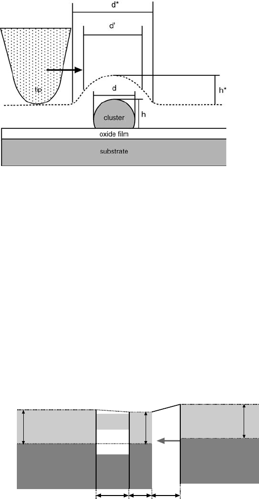
First, convolution effects between the tip and the cluster, both in general of
comparable size, must be considered. This has already been pointed out by Reis
et al. [40] in 1989 in the context of roughness measurement [40] and Barbet et al. in
1993 for imaging colloidal gold beads [41] using STM. The situation one encounters
for small metal particles on an oxide film is depicted in Figure 2.10. If we disregard
electronic effects, which will be discussed below, the trajectory of an STM tip above
a cluster will follow the dotted path depicted in Figure 2.10. Two consequences
become immediately obvious: (i) The apparent cluster height h
, which can be
derived, should be identical to the actual cluster height h. Thus, from this point of
view the cluster height can be correctly measured by STM. Since the height is in
general an integer multiple of a step height of the corresponding cluster material,
it is rather easy to judge on the number of atomic layers, which constitute the cluster.
(ii) The measured cluster diameter d
will be larger than the actual cluster diameter d.
Moreover, the actual value of d
will depend not only on the cluster diameter but also
on the morphology and radius of the tip. Even if we define the diameter of the cluster
at the FWHM in a line scan of the particle (d
0
), the measurement will still not reflect
2.4 STM Imaging of Metal Particles on Oxide Films
j
39
the actual diameter of the cluster. To account for this, a detailed analysis of the tip
shape is necessary, as it has been described in detail by Bowker et al. [5] as well as
Klyachko and Chen [42], for the case of C
60
molecules on Ge(1 0 0) and Si(1 0 0). But
even if we were able to overcome these geometric distortions by estimating the tip
shape and explicitly including it in the particle size calculations, a second and more
important problem will come into play.
The complex electronic structure of the tunneling contact in these systems, which
is schematically depicted in Figure 2.11, renders the tunneling process rather
difficult. We are now facing a junction of metal–oxide–metal–vacuum–metal type
and a number of effects have to be considered. First, the electronic structure of the
clusters will play an important role. Here, we have to consider again two cases: very
small particles, which still have – much like molecules – discrete electronic states [43],
and larger particles, which possess a band structure and can be regarded as metals.
We will confine our discussion to the latter case since most of the arguments found
there are also applicable to the former. For a metallic particle, the tunneling current
Figure 2.10 Trajectory of an STM tip above an oxide-supported metal particle.
tipsubstrate oxide
E
F
E
F
VB
CB
d
g
d
f
E
Vac
φ
s
φ
t
cluster
d
c
φ
c
Figure 2.11 Schematic representation of the tunneling gap for an oxide-supported metal particle.
40
j
2 The Template Route to Nanostructured Model Catalysts
from the tip can pass into the particle at all bias voltages much as it is the case on
extended metal surfaces because of the continuous band structure of the metal. As a
consequence, the tunneling resistivity will be to a first approximation related to the
electronic density of states of the cluster. However, once the tunneling electron has
passed the cluster, the further transport of the electron through the oxide film to the
substrate strongly depends on the band structure of the oxide film. If the bias voltage
is large, then the energy of the electron corresponds to that of the conduction band of
the oxide and tunneling is facilitated.
If, however, the bias voltage is low, the oxide film will act as an additional tunneling
barrier (see also Figure 2.5) and the electron may not as easily relax into the substrate.
In the latter case, charging effects of the particle may be encountered, which will
in turn influence the tunneling current and thus the apparent topography of the
particle. This will, however, depend on the thickness of the oxide film and thus the
second tunneling gap. We expect therefore that much like the apparent topography
of the oxide film, the apparent height and size of clusters on oxide films will show
strong bias dependence. This is shown in Figure 2.12 for a single Fe cluster on
Al
2
O
3
/Ni
3
Al(1 1 1).
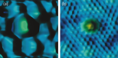
In Figure 2.12a, which was taken at a bias of 3.2 V, that is, in the range of the oxide
conduction band, the cluster appears rather large and the surrounding oxide film is
also imaged with large corrugation. At small bias voltage (Figure 2.12b), however,
the cluster appears to be much smaller and the oxide film is not visible any more.
The hexagonal pattern surrounding the cluster is due to the atomic structure of the
Ni
3
Al(1 1 1) substrate, which can be resolved in this case through the oxide film. By
comparing these images, the whole problem of particle size measurements on such
complex systems becomes very apparent.
To systematically investigate this phenomenon, a collection of 12 Fe clusters on
Al
2
O
3
/Ni
3
Al(1 1 1) has been imaged by STM in the bias voltage range from 0 to 5 V.
In Figure 2.13, it is clearly visible that not only the apparent structure of the oxide film
undergoes a strong bias dependence, as it has already been shown in the previous
section, but also the appearance of the clusters changes dramatically as a function of
bias voltage. A thorough analysis of the cluster heights and diameters as a function of
the bias voltages leads to the curves presented in Figure 2.14. It is visible at first glance
Figure 2.12 STM images of a single Fe cluster on Al
2
O
3
/
Ni
3
Al(1 1 1): (a) 3.2 V and (b) 0.19 V, 6.2 nm 6.2 nm [44].
2.4 STM Imaging of Metal Particles on Oxide Films
j
41
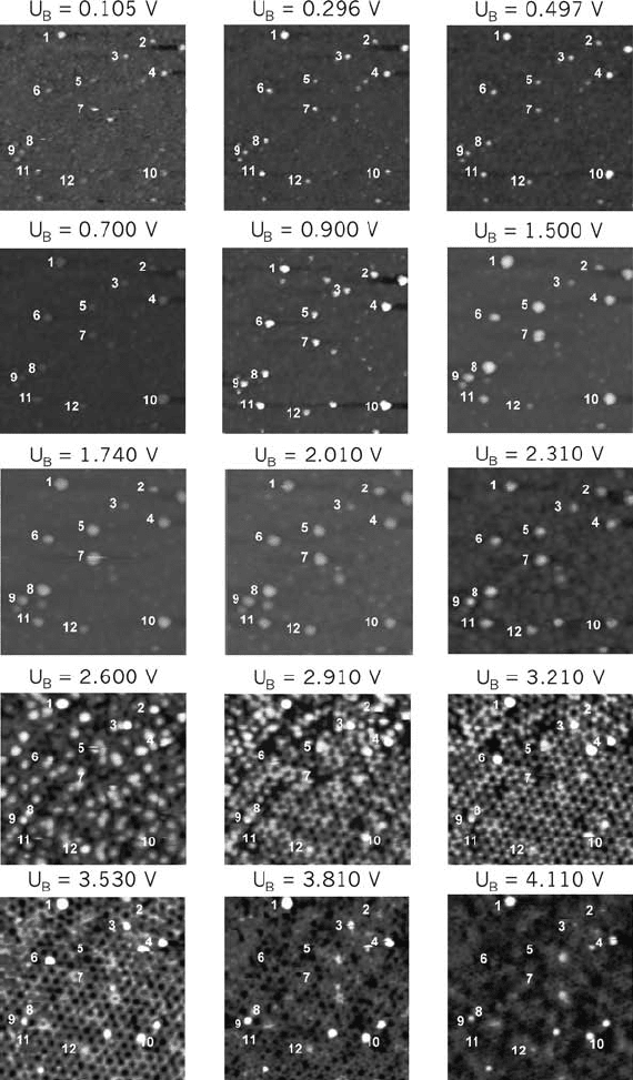
Figure 2.13 STM images of Fe clusters on Al
2
O
3
/Ni
3
Al(1 1 1)
taken for different sample bias voltages. The image size is
48 nm 48 nm. The labeled particles were used for the evaluation
of the particle height and diameter [44].
42
j
2 The Template Route to Nanostructured Model Catalysts
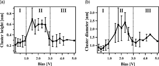
that the variations of cluster height and size are significant in the investigated range
of bias voltages. There are, however, three distinct regions, which show a particular
behavior. The range from 0 to 1 V is characterized only by a slight variation in the
cluster height and diameter. The same is true for the bias range above 3 V. However,
in between (1–3 V), an increase in the apparent height and diameter is encountered.
To explain this, we turn back to Figure 2.11. Region I is clearly in the bandgap of the
oxideso that aluminadoesnotcontributetothetunnelingprocess.RegionIIIisrelated
to the conduction band of the oxide so that the oxide is taking part in the tunneling
process, but the contribution of the oxide can be regarded as constant to a first
approximation. This implies that in these two regions theappearance of the clusters is
largely determined by the electronic structure of the cluster itself. Apparently, this
structure is not a strong function of the bias voltage in the present case. In region II,
however, we find a steep increase in both values. This must be due to the electronic
structureofthetunneling gap.Toexplainthisvariation,itisnecessarytohaveadetailed
look at electronic states, which participate in the tunneling process. Here, contribu-
tions of both the cluster and the oxide film have to be considered. First of all we note
that above 2 Va contrast reversal and an increase in the measured corrugation in the
STMimages of the pureoxidefilm was found,whichhas been discussedabove. This is
correlated with the appearance of the dots in the STM images exactly at the positions
where the clusters are located in the present case. This contrast reversal, which is due
to the electronic structure of the oxide film, can therefore explain the increased
values of the cluster height and diameter in the range from 2 to 3 V. For bias voltages
between 1 and 2 V, however, the increase in cluster height and diameter cannot be
attributed to thealumina band structure.Thus, itmustbe relatedto the bandstructure
of the Fe clusters themselves. Theoretical data from literature can shed some light on
the question whether or not the electronic structure of the clusters is responsible for
this sudden increase in Figure 2.14. The calculated density of states for an Fe cluster
containing 7 Fe atoms shows an intense empty sp-state that is localized in the range
from 1 to 2 eV [45]. This state will facilitate tunneling into the cluster and, thus, lead to
a decrease in the tunneling resistance. This in turn will, under constant current
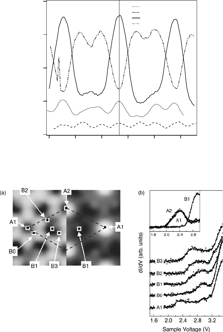
Figure 2.14 Apparent cluster height (a) and diameter (b) as a
function of bias voltage. Data were obtained from the Fe clusters
shown in Figure 2.13 [44].
2.4 STM Imaging of Metal Particles on Oxide Films
j
43