Dinc Ibrahim. Refrigeration systems and applications 2th edition
Подождите немного. Документ загружается.

Refrigeration System Components 131
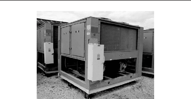
Figure 3.19 A typical air-cooled condenser (Courtesy of Trane Company).
On the other hand, they have some disadvantages as given below:
• high condensing temperatures,
• high refrigerant cost because of long piping runs,
• high power requirements per kW of cooling,
• high noise intensity, and
• multiple units required for large-capacity systems.
3.6.3 Evaporative Condensers
Evaporative condensers are apparently water-cooled designs and work on the principle of cooling
by evaporating water into a moving air stream. The effectiveness of this evaporative cooling process
depends upon the wet-bulb temperature of the air entering the unit, the volume of airflow, and the
efficiency of the air/water interface.
Evaporative condensers use water sprays and airflow to condense refrigerant vapors inside the
tubes. The condensed refrigerant drains into a tank called a liquid receiver. Refrigerant subcooling
can be accomplished by piping the liquid from the receiver back through the water sump where
additional cooling reduces the liquid temperature even further.
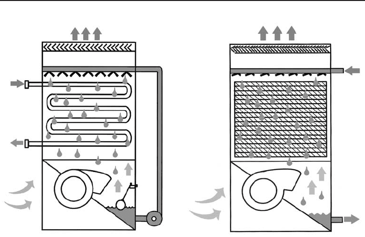
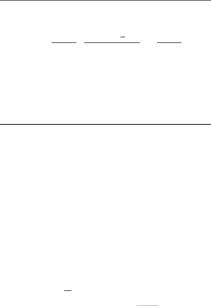
In an evaporative condenser (Figure 3.20a), the fluid to be cooled is circulated inside the tubes
of the unit’s heat exchanger. Heat flows from the process fluid through the coil tubes to the
water outside, which is cascading downward over the tubes. Air is forced upward through the
coil evaporating a small percentage of the water, absorbing the latent heat of vaporization, and
discharging the heat to the atmosphere. The remaining water falls to the sump to be recircu-
lated by the pump, while water entrained in the air stream is reclaimed and returned to the sump
by the mist eliminators at the unit discharge. The only water consumed is the amount evapo-
rated plus a small amount which is intentionally bled off to limit the concentration of impurities
in the pan. With the optional extended surface coil, the recirculating water pump can be shut-
off and the unit operated dry during periods of below-design ambient temperatures. Air is still
132 Refrigeration Systems and Applications
(a) (b)
Figure 3.20 (a) An evaporative condenser. (b) A counter-flow cooling tower (Courtesy of Baltimore Aircoil
International).
forced upward through the coil, but the heat is now dissipated to the atmosphere by sensible
cooling alone.
The following are some characteristics of these condensers:
• reduced circulating water for a given capacity,
• water treatment is necessary,
• reduced space requirement,
• small piping sizes and short overall lengths,
• small system pumps, and
• availability of large-capacity units and indoor configurations.
The volume of water used by evaporative condensers is significant. Not only does water evaporate
just to reject the heat, but water must be added to avoid the buildup of dissolved solids in the basins
of the evaporative condensers. If these solids build up to the point that they foul the condenser
surfaces, the performance of the unit can be greatly reduced.
3.6.4 Cooling Towers
Cooling towers (Figure 3.20b) are like evaporative condensers, working on the principle of cooling
by evaporating water into a moving air stream. The effectiveness of this evaporative cooling process
depends upon the wet-bulb temperature of the air entering the unit, the volume of airflow, and the
efficiency of the air or water interface.
As mentioned above, cooling towers are essentially large evaporative coolers where the cooled
water is circulated to a remote shell and tube refrigerant condenser. Note that the cooling water
Refrigeration System Components 133
is circulating through the tubes while refrigerant vapor condenses and gathers in the lower region
of the heat exchanger. Notice also that this area subcools the refrigerant below the temperature
of condensation by bringing the coldest cooling tower water into this area of the condenser. The
warmed cooling water is sprayed over a fill material in the tower. Some of it evaporates in the
moving air stream. The evaporative process cools the remaining water.
The volume of water used by cooling towers is significant. Not only does water evaporate just
to reject the heat but it must also be added to avoid the buildup of dissolved solids in the basins of
the cooling towers. If these solids build up to the point that they foul the condenser surfaces, the
performance of the unit can be greatly reduced.
3.6.5 Energy and Exergy Analyses of Condensers
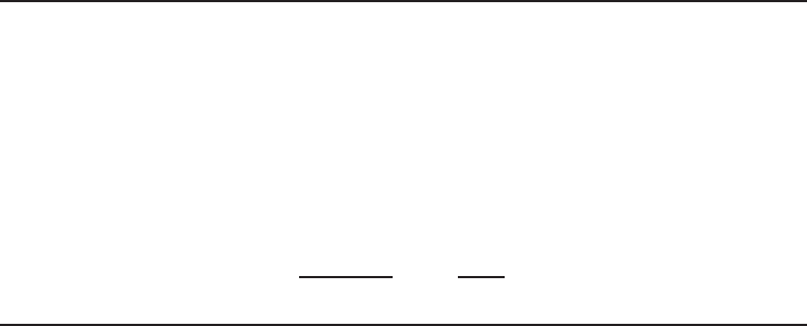
Condensers are used to reject heat from a refrigeration system. In a vapor-compression refrigeration
cycle, the refrigerant is cooled and condensed as it flows in the condenser coils as shown in
Figure 3.21a. The conservation of mass principle requires that
˙m
1
=˙m
2
(3.13)
Referring to Figure 3.21a, energy is entering and leaving by the refrigerant stream and heat is
rejected from the condenser, (
˙
Q
out
or
˙
Q
H
). The steady-flow energy balance can be written as (with
negligible kinetic and potential energies)
˙mh
1
=˙mh
2
+
˙
Q
out
(3.14)
˙
Q
out
=˙m(h
1
− h
2
)
In the condenser of a household refrigerator, heat is rejected from the refrigerant to the kitchen
air as it flows in the condenser coils. Figure 3.21a represents operation of such a compressor. In
some refrigeration applications (especially large ones), heat is rejected from the refrigerant into
water (water-cooled condenser) in a refrigerant-to-water heat exchanger as shown in Figure 3.21b.
Assuming that heat exchanger is insulated, the energy balance in this case becomes
˙m
R
h
1
+˙m
w
h
3
=˙m
R
h
2
+˙m
w
h
4
(3.15)
˙m
R
(h
1
− h
2
) =˙m
w
(h
4
− h
3
)
where ˙m
R
and ˙m
w
are the mass flow rates of the refrigerant and the water. The rate of heat rejected
to water is
˙
Q
out
=˙m
R
(h
1
− h
2
) =˙m
w
(h
4
− h
3
) (3.16)
Condenser
1
2
Refrigerant,
m
R
1
Water,
m
w
2
4
3
(
b
)(
a
)
Condenser
Q
H
·
·
·
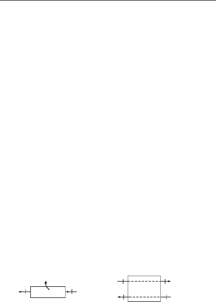
Figure 3.21 The schematic of condensers considered for mass and energy analysis. (a) Air-cooled condenser.
(b) Water-cooled condenser.
134 Refrigeration Systems and Applications
Referring to Figure 3.21a, an entropy balance on the condenser may be written as
˙
S
in
−
˙
S
out
+
˙
S
gen
=
˙
S
sys
= 0
˙
S
gen
=
˙
S
out
−
˙
S
in
(3.17)
˙
S
gen
=
˙
Q
H
T
H
+˙ms
2
−˙ms
1
=˙m
s
2
− s
1
+
q
H
T
H
Then the exergy destruction in the condenser becomes
˙
Ex
dest
= T
0
˙
S
gen
=˙mT
0
s
2
− s
1
+
q
H
T
H
(3.18)
The exergy destruction can also be determined by writing an exergy balance on the condenser:
˙
Ex
in
−
˙
Ex
out
−
˙
Ex
dest
= 0
˙
Ex
dest
=
˙
Ex
in
−
˙
Ex
out
(3.19)
˙
Ex
dest
= (
˙
Ex
1
−
˙
Ex
2
) −
˙
Ex
˙
Q
H
=˙m
[
h
1
− h
2
− T
0
(s
1
− s
2
)
]
−
˙
Q
H
1 −
T
0
T
H
The exergy efficiency of the condenser may be expressed as the ratio of the exergy of the heat
transferred to the high-temperature medium to the exergy decrease of the refrigerant across the
condenser:
η
ex,Cond
=
˙
Ex
˙
Q
H
˙
Ex
1
−
˙
Ex
2
=
˙
Q
H
1 −
T
0
T
H
˙m
[
h
1
− h
2
− T
0
(s
1
− s
2
)
]
= 1 −
˙
Ex
dest
˙
Ex
1
−
˙
Ex
2
(3.20)
If we consider Figure 3.21b for the operation of an evaporator, an entropy balance may be
written as
˙
S
gen
=
˙
S
out
−
˙
S
in
˙
S
gen
= ( ˙m
R
s
2
+˙m
w
s
4
) − ( ˙m
R
s
1
+˙m
w
s
3
) (3.21)
=˙m
R
(s
2
− s
1
) −˙m
w
(s
3
− s
4
)
Then the exergy destruction in the evaporator becomes
˙
Ex
dest
= T
0
˙
S
gen
= T
0
[
˙m
R
(s
2
− s
1
) −˙m
w
(s
3
− s
4
)
]
(3.22)
Example 3.2
Refrigerant-134a enters the condenser of a refrigeration cycle at 800 kPa and 60
◦
C with a flow rate
of 0.095 kg/s and leaves at the same pressure subcooled by 3.3
◦
C. The refrigerant is condensed by
rejecting its heat to water which experiences a temperature rise of 11
◦
C. Determine (a) the rate of
heat rejected in the condenser, (b) the mass flow rate of water, (c) the COP of this refrigeration
cycle if the cooling load at these conditions is 12 kW, and (d) the rate of exergy destruction in the
condenser. Take T
0
= 25
◦
C.
Refrigeration System Components 135
Solution
(a) We refer to Figure 3.21b for the schematic of the condenser. The properties of refrigerant at
the inlet and exit states of the condenser are (from Tables B.3, B.4, and B.5)
P
1
= 800 kPa
T
1
= 60
◦
C
h
1
= 296.81 kJ/kg
s
1
= 1.011 kJ/kg · K
P
2
= 800 kPa
T
2
= T
sat @ 800 kPa
− T
subcool
= 31.3 − 3.3 = 28
◦
C
h
2
∼
=
h
f @28
◦
C
= 90.69 kJ/kg
s
2
∼
=
s
f @28
◦
C
= 0.3383 kJ/kg · K
The rate of heat rejected in the condenser is
˙
Q
H
=˙m
R
(h
1
− h
2
) = (0.095 kg/s)(296.81 − 90.69) kJ/kg = 19.58 kW
(b) The mass flow rate of water can be determined from an energy balance on the condenser:
˙
Q
H
=˙m
R
(h
1
− h
2
) =˙m
w
c
p
T
w
19.58 kW =˙m
w
(4.18 kJ/kg ·
◦
C)(11
◦
C)
˙m
w
= 0.426 kg/s
The specific heat of water is taken to be 4.18 kJ/kg ·
◦
C.
(c) From the definition of COP for a refrigerator,
COP =
˙
Q
L
˙
W
in
=
˙
Q
L
˙
Q
H
−
˙
Q
L
=
12 kW
(19.58 − 12) kW
= 1.58
(d) The entropy generation and the exergy destruction in the condenser are
˙
S
gen
=˙m
R
(s
2
− s
1
) +
˙
Q
H
T
H
= (0.095 kg/s)(0.3383 − 1.011) kJ/kg · K +
19.58 kW
298 K
= 0.001794 kW/K
˙
Ex
dest
= T
0
˙
S
gen
= (298 K)(0.001794 kJ/kg · K) = 0.5345 kW
3.7 Evaporators
Evaporator can be considered as the point of heat capture in a refrigeration system and provides
the cooling effect required for any particular application. There are almost as many different types
of evaporators as there are applications of heat exchangers. However, evaporators are divided into
two categories such as (i) direct cooler evaporators that cool air that, in turn, cools the product
and (ii) indirect cooler evaporators that cool a liquid such as brine solution that, in turn, cools
the product. Normally, the proper evaporator comes with the system. However, there may be an
occasion when designing a system, that one will need to determine the requirements and select the
proper evaporator from a manufacturer’s catalog or manual.
In practice, the following evaporators are commonly used for cooling, refrigerating, freezing,
and air-conditioning applications:
• liquid coolers,
• air coolers, and/or gas coolers.
136 Refrigeration Systems and Applications
Shell
Baffle and
support plate
Shell
fluid
Tube
fluid
Head
Tie rod and
spacer
Tube
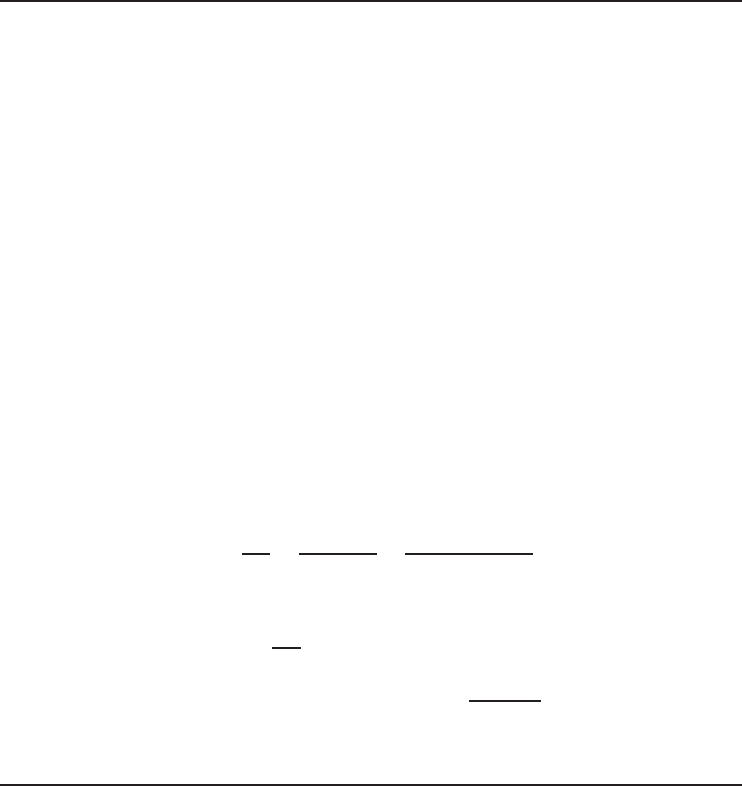
Figure 3.22 A shell-tube type evaporator (Bejan, 2004).
3.7.1 Liquid Coolers
Shell and tube type heat exchangers (Figure 3.22) are the more common form of evaporation units
for water cooling and chilling applications. These are utilized to cool liquids, which can be used
as the secondary refrigerant or to cool the final products directly. In practice, these types of heat
exchangers are known as liquid coolers or chillers.
Some example applications in food and refrigeration industry are
• chilling of drinkable water,
• chilling of water for air-conditioning coils,
• chilling of milk after pasteurization, and
• process cooling operations.
Chilled water systems can use either a flooded evaporator or a direct expansion evaporator which
are typically shell and tube type heat exchangers. In a flooded evaporator, refrigerant floods the
shell side of the heat exchanger and is controlled by a level valve. Water being chilled passes
through the tubes. Conversely, in a direct expansion evaporator, water is carried in the shell and
refrigerant is boiled inside the tubes. The rate of refrigerant flow is throttled to insure that only
refrigerant gas exits the evaporator. Copper tubes mounted within a carbon steel shell is the most
common construction used for chilled water evaporators.
It is important to note that if the refrigerant vaporizes on the outside surface of the tubes the
evaporator is a flooded cooler; if it vaporizes inside the tubes the evaporator is a dry cooler (note
that in this more common type, the mixture of liquid and vapor is evaporated completely), usu-
ally with some degree of superheating (Hewitt, Shires and Bott, 1994). In a flooded cooler the
water or brine is circulated through the tubes, which are usually finned to provide an incre-
ment in the heat-transfer rate and a decrease in the evaporator size. In a dry cooler the liq-
uid refrigerant is contained within the tubes, and water or brine is circulated through the shell
of the cooler, which serves as an evaporator. Flooded coolers are often specified for applica-
tions where shell-side vaporization of refrigerant of other liquids is desirable. Due to rapid boil-
ing in the shell, in order to obtain high purity vapors, a vapor disengagement vessel is often
welded to the main shell. Flooded coolers are particularly employed in multiple compressor
systems.
Refrigeration System Components 137
(a)
(
b
)
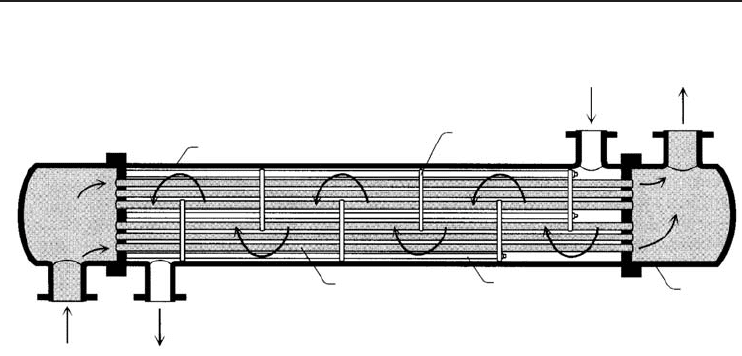
Figure 3.23 Air coolers. (a) Room type. (b) Large-scale industrial type (Courtesy of Super Radiator Coils).
3.7.2 Air and Gas Coolers
These coolers are generally called direct expansion coils and consist of a series of tubes through
which refrigerant flows (Figure 3.23). The tubes, which are finned to increase the heat-transfer rate
from the medium to be cooled (e.g., air) to the boiling point, are normally arranged into a number
of parallel circuits fed from a single throttling valve. The hot refrigerant vapor is accumulated in the
outlet (suction) gas header. These direct expansion coils are used only in the positive displacement
compressor systems, owing to quite low-pressure ratios. Like liquid coolers, these coolers are also
classified as flooded and dry types. In a flooded coil, a float valve is used to maintain the preset
level in the coil, meaning that evaporator coil is kept close to full of the liquid refrigerant. This full
contact of the liquid with the tube walls provides a high heat-transfer rate. In practical applications,
flooded-type evaporators are not preferable, because they require large amounts of refrigerant. A
dry coil requires only a small amount of refrigerant and this reduces the cost of the refrigerant
charge. Sometimes a metering device (thermal expansion valve) regulates the amount of the liquid
entering the coil to maintain a predetermined amount of superheat in the refrigerant at the coil
outlet. The dry expansion coil contains mostly liquid at the inlet and only superheated vapor at
the outlet, after absorbing heat from the medium to be cooled. In the air coolers, when the surface
temperatures fall below 0
◦
C, frosting occurs. Thick layers of frost act as insulation and reduce the
airflow rate (in the forced convection coils) and the available inner space.
Several methods are used for defrosting, for example, hot-gas defrost and water defrost. But
recently, frost-free refrigeration systems have become popular because of the problems men-
tioned above.
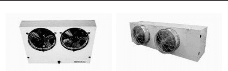
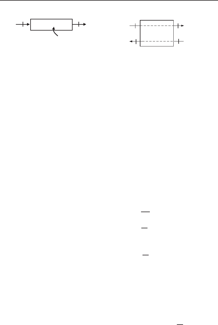
3.7.3 Energy and Exergy Analyses of Evaporators
Evaporators are used to absorb heat from the refrigerated space. In a vapor-compression refrigeration
cycle, the refrigerant is evaporated as it flows in the evaporator coils as shown in Figure 3.24a.
The conservation of mass principle requires that
˙m
1
=˙m
2
(3.23)
Referring to Figure 3.24a, energy is entering and leaving by the refrigerant stream and heat is
absorbed from the cooled space, (
˙
Q
in
or
˙
Q
L
). The steady-flow energy balance can be written as
(with negligible kinetic and potential energies)
˙mh
1
+
˙
Q
in
=˙mh
2
(3.24)
˙
Q
in
=˙m(h
2
− h
1
)
138 Refrigeration Systems and Applications
Evaporator
2
1
Q
L
Refrigerant,
m
R
Evaporator
3
Water,
m
w
4
2
1
(a) (b)
·
·
·
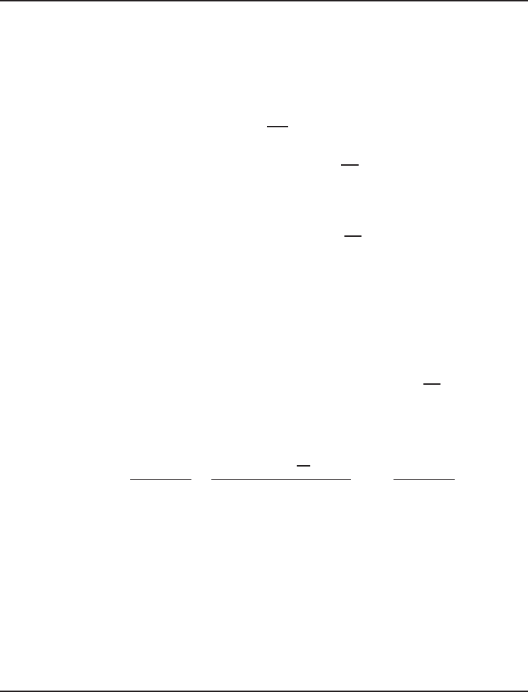
Figure 3.24 The schematic of evaporators considered for mass and energy analysis. (a) Refrigerant absorbing
heat from a space. (b) Refrigerant absorbing heat from water.
In the evaporator of a household refrigerator, heat is absorbed from the freezer section as it flows
in the evaporator coils. Figure 3.24a represents operation of such a compressor. Some refrigeration
systems are used to cool a fluid stream in the evaporator. Figure 3.24b shows a heat exchanger
operating as an evaporator in which water is cooled as the refrigerant is evaporated. Assuming that
heat exchanger is insulated, the energy balance in this case becomes
˙m
R
h
1
+˙m
w
h
3
=˙m
R
h
2
+˙m
w
h
4
(3.25)
˙m
R
(h
2
− h
1
) =˙m
w
(h
3
− h
4
)
where ˙m
R
and ˙m
w
are the mass flow rates of the refrigerant and the water. The rate of heat absorbed
by the refrigerant (and rejected from the water) is
˙
Q
in
=˙m
R
(h
2
− h
1
) =˙m
w
(h
3
− h
4
) (3.26)
Referring to Figure 3.24a, an entropy balance on the evaporator may be written as
˙
S
in
−
˙
S
out
+
˙
S
gen
=
˙
S
sys
= 0
˙
S
gen
=
˙
S
out
−
˙
S
in
(3.27)
˙
S
gen
=˙ms
2
−˙ms
1
−
˙
Q
H
T
H
=˙m
s
2
− s
1
−
q
L
T
L
Then the exergy destruction in the evaporator becomes
˙
Ex
dest
= T
0
˙
S
gen
=˙mT
0
s
2
− s
1
−
q
L
T
L
(3.28)
The exergy destruction can also be determined by writing an exergy balance on the evaporator:
˙
Ex
in
−
˙
Ex
out
−
˙
Ex
dest
= 0
˙
Ex
dest
=
˙
Ex
in
−
˙
Ex
out
˙
Ex
dest
=−
˙
Ex
˙
Q
L
+
˙
Ex
1
−
˙
Ex
2
(3.29)
˙
Ex
dest
= (
˙
Ex
1
−
˙
Ex
2
) −
˙
Ex
˙
Q
L
=˙m
[
h
1
− h
2
− T
0
(s
1
− s
2
)
]
−
−
˙
Q
L
1 −
T
0
T
L
Refrigeration System Components 139
The exergy efficiency of the evaporator may be expressed as the ratio of the exergy increase of
the cold space as a result of losing heat to the exergy decrease of the refrigerant due to receiving
heat from the cold reservoir.
η
ex,Evap
=
˙
Ex
˙
Q
L
˙
Ex
1
−
˙
Ex
2
=
−
˙
Q
L
1 −
T
0
T
L
˙m
[
h
1
− h
2
− T
0
(s
1
− s
2
)
]
= 1 −
˙
Ex
dest
˙
Ex
1
−
˙
Ex
2
(3.30)
If we consider Figure 3.24b for the operation of an evaporator, an entropy balance may be
written as
˙
S
gen
=
˙
S
out
−
˙
S
in
˙
S
gen
= ( ˙m
R
s
2
+˙m
w
s
4
) − ( ˙m
R
s
1
+˙m
w
s
3
) (3.31)
=˙m
w
(s
4
− s
3
) −˙m
R
(s
1
− s
2
)
Then the exergy destruction in the evaporator becomes
˙
Ex
dest
= T
0
˙
S
gen
= T
0
[
˙m
w
(s
4
− s
3
) −˙m
R
(s
1
− s
2
)
]
(3.32)
Example 3.3
Heat is absorbed from a cooled space at 32
◦
F at a rate of 320 Btu/min by refrigerant-22
that enters the evaporator at −12
◦
F with a quality of 0.3 and leaves as saturated vapor at
the same pressure. Determine (a) the volume flow rates of R-22 at the evaporator inlet and
outlet and (b) the rate of exergy destruction in the evaporator and the exergy efficiency of the
evaporator. Take T
0
= 77
◦
F. The properties of R-22 at the inlet and exit of the evaporator are
as follows:
h
1
= 102.67 Btu/lbm, s
1
= 0.2776 Btu/lbm · R, v
1
= 0.5332 ft
3
/lbm
h
2
= 169.82 Btu/lbm, s
2
= 0.4276 Btu/lbm · R, v
2
= 1.750 ft
3
/lbm
Solution
(a) The mass flow rate of R-22 may be determined from an energy balance on the evaporator to
be (see Figure 3.24a)
˙
Q
L
=˙m(h
2
− h
1
) −→ 320/60 Btu/s =˙m(169.82 − 102.67) Btu/lbm −→ ˙m = 0.0794 lbm/s
The volume flow rate at the evaporator inlet and outlet are
˙
V
1
=˙mv
1
= (0.0794 lbm/s)(0.5332 ft
3
/lbm) = 0.04235 ft
3
/s = 2.54 ft
3
/min
˙
V
2
=˙mv
2
= (0.0794 lbm/s)(1.750 ft
3
/lbm) = 0.139 ft
3
/s = 8.34 ft
3
/min
(b) The entropy generation and the exergy destruction are
˙
S
gen
=˙m(s
2
− s
1
) −
˙
Q
L
T
L
= (0.0794 lbm/s)(0.4276 − 0.2776) Btu/lbm · R −
5.33 Btu/s
492 R
= 0.001073 Btu/s · R
˙
Ex
dest
= T
0
˙
S
gen
= (537 R)(0.001073 Btu/s · R) = 0.576 Btu/s
140 Refrigeration Systems and Applications
The exergy decrease of the refrigerant as it flows in the evaporator is
˙
Ex
1
−
˙
Ex
2
=˙m(h
1
− h
2
) −˙mT
0
(s
1
− s
2
)
= 5.33 − (0.0794 lbm/s)(537 R)(0.2776 − 0.4276) Btu/lbm · R
= 1.06 Btu/s
The exergy efficiency is then
η
ex,Evap
= 1 −
˙
Ex
dest
˙
Ex
1
−
˙
Ex
2
= 1 −
0.576
1.06
= 0.458 = 45.8%
3.8 Throttling Devices
In practice, throttling devices, called either expansion valves or throttling valves, are used to reduce
the refrigerant condensing pressure (high pressure) to the evaporating pressure (low pressure) by a
throttling operation and regulate the liquid-refrigerant flow to the evaporator to match the equipment
and load characteristics. These devices are designed to proportion the rate at which the refrigerant
enters the cooling coil to the rate of evaporation of the liquid refrigerant in the coil; the amount
depends, of course, on the amount of heat being removed from the refrigerated space. The most
common throttling devices are
• thermostatic expansion valves,
• constant-pressure expansion valves,
• float valves, and
• capillary tubes.
Note that a practical refrigeration system may consist of a large range of mechanical and elec-
tronic expansion valves and other flow-control devices for small- and large-scale refrigeration
systems, comprising thermostatic expansion valves, solenoid valves, thermostats and pressostats,
modulating pressure regulators, filter driers, liquid indicators, nonreturn valves and water valves,
and furthermore, decentralized electronic systems for full regulation and control.
3.8.1 Thermostatic Expansion Valves
The thermostatic expansion valves are essentially reducing valves between the high-pressure side
and the low-pressure side of the system. These valves, which are the most widely used devices,
automatically control the liquid-refrigerant flow to the evaporator at a rate that matches the system
capacity to the actual load. They operate by sensing the temperature of the superheated refrigerant
vapor leaving the evaporator. For a given valve type and refrigerant, the associated orifice assembly
is suitable for all versions of the valve body and in all evaporating temperature ranges.
When the thermostatic expansion valve is operating properly, the temperature at the outlet side
of the valve is much lower than that at the inlet side. If this temperature difference does not exist
when the system is in operation, the valve seat is probably dirty and clogged with foreign matter.
Once a valve is properly adjusted, further adjustment should not be necessary. The major problem
can usually be traced to moisture or dirt collecting at the valve seat and orifice. Figure 3.25 shows
a common type of electrically driven expansion valve.