Dinc Ibrahim. Refrigeration systems and applications 2th edition
Подождите немного. Документ загружается.

Refrigeration System Components 151
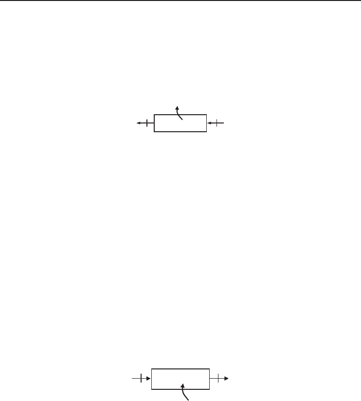
3.38 Heat is rejected from the condenser of a heat pump cycle by refrigerant-134a entering
at 700 kPa and 50
◦
C at a rate of 105 kg/h and leaves as a saturated liquid. Determine
(a) the temperature of R-134a at the condenser exit, (b) the volume flow rate at the
exit of the condenser in L/min, (c) the COP of the heat pump if the rate of heat
absorbed in the evaporator is 12,000 Btu/h, and (d) the rate of exergy destruction. Take
T
0
= 77
◦
F.
Condenser
12
Q
H
·
3.39 A vapor-compression refrigeration cycle uses ammonia as the working fluid. Heat is rejected
from ammonia to air in the condenser. The air enters at 70
◦
F at a rate of 45 lbm/min
and leaves at 85
◦
F. Ammonia experiences an enthalpy change of 86 Btu/lbm as it flows
through the condenser. Determine (a) the rate of heat rejected in the condenser in Btu/h
and (b) the ratio of mass flow rates of air and ammonia. Take the specific heat of air to be
0.240 Btu/lbm·
◦
F.
Evaporators
3.40 How can evaporators be classified?
3.41 List some applications of liquid coolers in refrigeration.
3.42 What is the difference between the operation of a flooded evaporator and a direct expansion
evaporator (also called dry cooler)? Which one is more preferable?
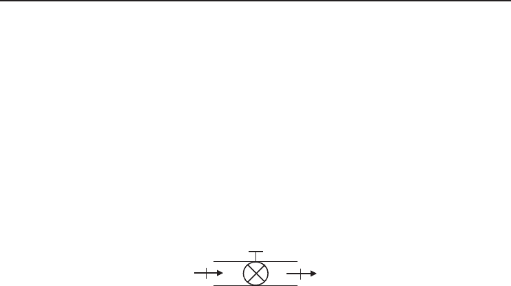
3.43 Heat is absorbed from a cooled space at a rate of 320 kJ/min by refrigerant-22 that enters the
evaporator at −10
◦
C with a quality of 0.3 and leaves as saturated vapor at the same pressure.
Determine the volume flow rates of R-22 at the compressor inlet and outlet. The properties
of R-22 at the inlet and exit of the evaporator are as follows: h
1
= 252.16 kJ/kg, v
1
=
0.02010 m
3
/kg, h
2
= 401.10 kJ/kg, v
2
= 0.06523 m
3
/kg
Evaporator
21
Q
L
·
3.44 Refrigerant-134a enters the expansion valve of a refrigeration cycle at 900 kPa as a saturated
liquid with a flow rate of 150 L/h. R-134a leaves the evaporator at 100 kPa superheated by
6.4
◦
C. The refrigerant is evaporated by absorbing heat from air which is cooled from 15
to 2
◦
C. Determine (a) the rate of heat absorbed in the evaporator, (b) the mass flow rate of
air, (c) the COP of the cycle if the compressor work input is 72.5 kJ/kg, and (d) the rate of
entropy generation and exergy destruction in the evaporator. Take T
0
= 25
◦
C.
3.45 A heat pump operates on a vapor-compression refrigeration cycle with R-134a as the refrig-
erant. R-134a enters the evaporator at −12.7
◦
C with a vapor mass fraction of 27% and
leaves at the same pressure as a saturated vapor. The refrigerant is evaporated by absorbing
heat from ambient air at 0
◦
C. Determine (a) the amount of heat absorbed from the ambient
air and (b) the exergy destruction in the evaporator, both per unit mass flow rate of the
refrigerant.
152 Refrigeration Systems and Applications
Throttling Devices
3.46 List the most common throttling devices.
3.47 Can thermostatic expansion valves control the rate of liquid-refrigerant flow to the evapo-
rator? If so, how is this done?
3.48 If there is no temperature drop across a thermostatic expansion valve, what could be the
reason? Explain.
3.49 Explain characteristics of capillary tubes.
3.50 Refrigerant-134a enters the throttling valve of a heat pump system at 200 psia as a saturated
liquid and leaves at 20 psia. Determine (a) the temperature drop across the throttling valve
and (b) the entropy generation and the exergy destruction during this process. Take T
0
=
77
◦
F.
21
3.51 Refrigerant-502 (a blend of R-115 and R-22) enters the throttling valve of a heat pump
system at 45
◦
C as a saturated liquid and leaves at −22
◦
C as a mixture of saturated liquid
and vapor. Determine (a) the pressures at the inlet and exit of the valve and the vapor mass
fraction at the exit and (b) the entropy generation during this process. R-502 properties are
not available in the book. Use other sources to solve this problem.
Auxiliary Devices
3.52 List auxiliary devices used in refrigeration systems.
3.53 What is the purpose of using an accumulator?
3.54 What is the purpose of using a receiver?
3.55 What is the purpose of using an oil separator?
3.56 What is the purpose of using a strainer? What types are available?
3.57 What is the purpose of using a drier? Which factors influence the selection of the correct
size of a drier?
3.58 What is the purpose of using a check valve?
3.59 Describe the operation of a defrost controller with timer.
References
ARI (2000) Variable Capacity Positive Displacement Refrigerant Compressors and Compressor Units for Air
Conditioning and Heat Pump Applications, Standard 500-2000, Air Conditioning and Refrigeration Institute,
Arlington, VA.
Bejan, A. (2004) Convection Heat Transfer, 3rd edn, John Wiley & Sons, Ltd., London.
Awberry, J.H. (1942) Carl von Linde: a pioneer of deep refrigeration. Nature, 149, 630.
Critchell, J.T. and Raymond, J. (1912) A History of Frozen Meat Trade, 2nd edn, London, pp. 4–5.

Refrigeration System Components 153
DETR (1999) The Engine of the Refrigeration System: Selecting and Running Compressors for Maximum Effi-
ciency, vol. 52, The Department of the Environment, Transport and Regions’ Energy Efficiency Best Practice
Programme, London General Information Leaflet, p. 8.
Dincer, I. (1997) Heat Transfer in Food Cooling Applications, Taylor & Francis, Washington, DC.
Dincer, I. (2003) Refrigeration Systems and Applications, 1st edn, John Wiley & Sons, Ltd., New York.
DOI (1952) Report of the Commissioner of Patents for the Year 1951 , U.S. Department of Interior, Patent
Office, Washington, DC, p. 76.
Duncan, T. (1999) The rotary screw compressor. ASHRAE Journal, 41, 34–36.
Goosman, J.C. (1924) History of refrigeration. Ice and Refrigeration, 67, 329.
Heap, R.D. (1979) American heat pumps in British houses . Elektrow¨arme International 35 , A2, A77–A81.
Hewitt, G.F., Shires, G.L. and Bott, T.R. (1994) Process Heat Transfer, CRC Press, Boca Raton, FL.
Langley, B.C. (1982) Basic Refrigeration, Reston Publishing Company, Reston, VA.
Langley, B.C. (1983) Heat Pump Technology , Reston Publishing Company, Reston, VA.
Neuberger, A. (1930) The Technical Arts and Sciences of the Ancients, (ed. H.L. Brose), tr. New York, p. 123.
Roelker, H.B. (1906) The Allen dense air refrigerating machine . Transactions American Soc. Refrig. Engineers,
2, 52–54.
Travers, M.W. (1946) Liquefaction of Gases, vol. 14, Encyclopaedia Britannica, Chicago, pp. 172–173.
Woolrich, W.R. (1947) Mechanical refrigeration – its American birthright. Refrigerating Engineering, 53, 250.

4
Refrigeration Cycles and Systems
4.1 Introduction
Refrigeration is used in industry for cooling and freezing of products, condensing vapors, main-
taining environmental conditions, and for cold storage. The number of different applications is
huge and they are a major consumer of electricity. In some sectors, particularly food, drink, and
chemicals it represents a significant proportion of overall site energy costs (up to 90% in the case
of some cold storage facilities) (Dincer, 2003).
Presently, the refrigeration industry urgently needs (i) technical information on the refrigeration
systems, system components, and technical and operational aspects of such systems and compo-
nents; (ii) procedures for energy and exergy analyses of refrigeration systems for system design
and optimization; (iii) application of optimum refrigeration techniques; (iv) techniques for the mea-
surement and evaluation of the components’ performance; and (v) methodology for the use of the
cooling data to design an efficient and effective refrigeration system and/or to improve the existing
refrigeration systems.
The primary objective of this chapter is to discuss refrigeration cycles and their energy and
exergy analyses, some new refrigeration techniques for more efficient and effective refrigeration,
and to provide some illustrative and practical examples to highlight the importance of the topic and
show how to conduct energy and exergy analyses for the refrigeration systems.
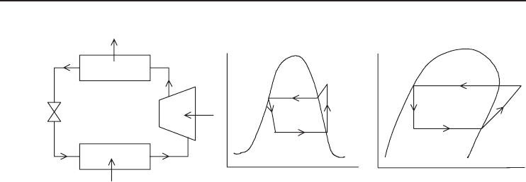
4.2 Vapor-Compression Refrigeration Systems
In practical applications, vapor-compression refrigeration systems are the most commonly used
refrigeration systems, and each system employs a compressor. In a basic vapor-compression refrig-
eration cycle as shown in Figure 4.1, four major thermal processes take place as follows:
• evaporation,
• compression,
• condensation, and
• expansion.
4.2.1 Evaporation
Unlike freezing and melting, evaporation and condensation occur at almost any temperature and
pressure combination. Evaporation is the gaseous escape of molecules from the surface of a liquid
and is accomplished by the absorption of a considerable quantity of heat without any change
in temperature. Liquids (e.g., refrigerants) evaporate at all temperatures with increased rates of
Refrigeration Systems and Applications
˙
Ibrahim Dinc¸er and Mehmet Kano
ˇ
glu
2010 John Wiley & Sons, Ltd
156 Refrigeration Systems and Applications
Evaporator
Condenser
Compressor
Expansion
valve
1
2
3
4
Q
H
W
(a)
1
2
3
4
Entropy (kJ/kg·K)
Temperature (K)
(b)
1
2
3
4
Enthalpy (kJ/kg)
Pressure (kPa)
(c)
·
·
Q
L
·
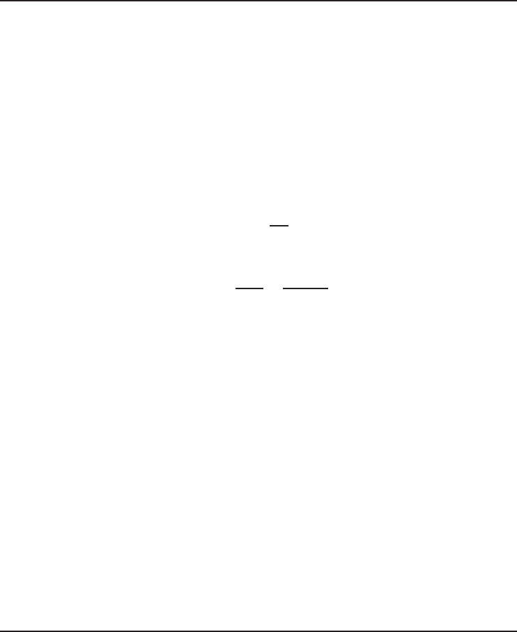
Figure 4.1 (a) A basic vapor-compression refrigeration system, (b) its T -s diagram, and (c) its log P-h
diagram.
evaporation occurring at higher temperatures. The evaporated gases exert a pressure called the
vapor pressure. As the temperature of the liquid rises, there is a greater loss of the liquid from
the surface, which increases the vapor pressure. In the evaporator of a refrigeration system, a
low-pressure cool refrigerant vapor is brought into contact with the medium or matter to be cooled
(i.e., heat sink), absorbs heat, and hence boils, producing a low-pressure saturated vapor.
4.2.2 Compression
Using shaft work of a compressor raises the pressure of the refrigerant vapor obtained from the
evaporator. The addition of heat may play a role in raising the pressure. Increasing the gas pressure
raises the boiling and condensing temperature of the refrigerant. When the gaseous refrigerant is
sufficiently compressed, its boiling point temperature is higher than the heat sink’s temperature.
4.2.3 Condensation
This is a process of changing a vapor into a liquid by extracting heat. The high-pressure gaseous
refrigerant, which carries the heat energy absorbed in the evaporator and the work energy from
the compressor, is brought into the condenser. The condensing temperature of the refrigerant is
higher than that of the heat sink and therefore heat transfer condenses the high-pressure refrigerant
vapor to the high-pressure saturated liquid. The heat source has been cooled by pumping heat to
the heat sink. Instead of using a condenser to reject heat, the refrigerant vapor can be discharged
to the atmosphere, but this technique is impractical. Condensing the refrigerant gas allows reuse
at the beginning of the next cycle. In some practical applications, it is desired that the condenser
cools the refrigerant further, below the condensation temperature. This is called subcooling,which
is usually observed in the condenser to reduce flashing when the refrigerant pressure is reduced in
the throttling device. This method provides a reduction in the amount of gas entering the evaporator
and hence an improvement in the system performance (Dincer, 1997).
4.2.4 Expansion
The condensed refrigerant liquid is returned to the beginning of the next cycle. A throttling device
such as a valve, orifice plate, or capillary tube for the expansion process is used to reduce the

Refrigeration Cycles and Systems 157
pressure of the refrigerant liquid to the low-pressure level and the boiling temperature of the
refrigerant to below the temperature of the heat source. Energy losses through this pressure reduction
must be offset by additional energy input at the pressurization stage.
Figure 4.1a shows a schematic diagram of a basic vapor-compression refrigeration system.
For better understanding, this refrigeration cycle is shown by temperature–entropy (T –s)and
pressure–enthalpy (log P –h) diagrams as given in Figure 4.1b and c. Along the lines of the steps
given above, the operation of this system is as follows:
• (1–2) Reversible adiabatic compression. From the evaporator, low-pressure saturated refriger-
ant vapor comes to the compressor and is compressed into the condenser by volume reduction
and increased pressure and temperature.
• (2–3) Reversible heat rejection at constant pressure. From the compressor, high-pressure
refrigerant vapor enters the condenser and is liquefied by employing water or air.
• (3–4) Irreversible expansion at constant enthalpy. From the condenser, high-pressure saturated
refrigerant liquid passes through an expansion valve and its pressure and temperature are reduced.
• (4−1) Reversible heat addition at constant pressure. From the expansion valve, low-pressure
refrigerant liquid arrives in the evaporator. It boils here and in the process absorbs heat from the
surrounding medium, thereby providing a cooling effect.
As shown in Figure 4.1, the essential components of a simple vapor-compression refrigeration
system, as explained earlier, are as follows:
• Evaporator. This is the device where there is heat exchange for providing refrigeration, and
therefore it boils the liquid refrigerant at a low temperature, which causes the refrigerant to
absorb heat.
• Suction line. This is the tube between the evaporator and the compressor. After the liquid has
absorbed the heat, the suction line carries the refrigerant to the compressor. In this line, the
refrigerant is a superheated gas.
• Compressor. This device separates the low-pressure side of the system from the high-pressure
side and has two main goals: (i) to remove vapor from the evaporator to keep the evaporator’s
boiling point low and (ii) to compress the low-temperature refrigerant vapor into a small volume,
creating a high-temperature, high-pressure superheated vapor.
• Hot gas discharge line. This tube connects the compressor with the condenser. After the com-
pressor has discharged the high-pressure, high-temperature superheated refrigerant vapor, the hot
gas discharge line carries it to the condenser.
• Condenser. This device is used for heat exchange, similar to the evaporator, except that its job
is to expel heat, not absorb it. The condenser changes the state of the superheated refrigerant
vapor back into a liquid. This is done by creating a high pressure that raises the boiling point of
the refrigerant and removes enough heat to cause the refrigerant to condense back into a liquid.
• Liquid line. This line connects the condenser with the refrigerant control device, including the
expansion valve. Only liquid refrigerant should be in this line. Also, the line will be somewhat
warm because the refrigerant is still under high pressure.
• Refrigerant control. This last control works as a metering device. It monitors the liquid refriger-
ant that enters the evaporator and makes sure that all the liquid is boiled off before the refrigerant
goes to the suction line. If liquid refrigerant enters the suction line, it will enter the compressor
and cause it to fail.
In addition to the above listed components, there are some additional features, for example,
liquid receiver, service valves, suction service valve, discharge service valve, and liquid receiver
service valve, which can enhance the refrigeration system’s operation.
158 Refrigeration Systems and Applications
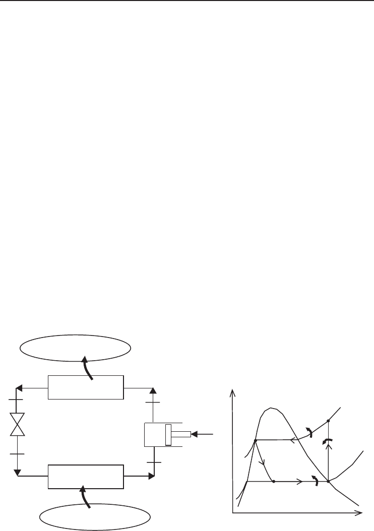
4.3 Energy Analysis of Vapor-Compression Refrigeration Cycle
A vapor-compression refrigeration cycle consists of a number of flow processes as mentioned above
and can be analyzed by applying steady-state flow according to the first law of thermodynamics, as
applied to each of the four components individually (Figure 4.2a), since energy must be conserved
by each component and also by the whole system. Therefore, the energy balance equation for each
component of the system is as follows (with the assumption that the changes in kinetic and potential
energies are negligible)
For compressor:
˙
E
in
=
˙
E
out
˙mh
1
+
˙
W =˙mh
2
(4.1)
˙
W =˙m(h
2
− h
1
)
where ˙m is mass flow rate of refrigerant, kg/s; h is enthalpy, kJ/kg; and
˙
W is compressor power
input, kW.
For condenser:
˙mh
2
=˙mh
3
+
˙
Q
H
(4.2)
˙
Q
H
=˙m(h
2
− h
3
)
where
˙
Q
H
is the heat rejection from the condenser to the high-temperature environment.
For expansion valve:
˙mh
3
=˙mh
4
h
3
= h
4
(4.3)
(
a
)(
b
)
Q
H
Condenser
Evaporator
Compressor
Expansion
valve
Q
L
W
T
L
T
H
1
2
3
4
Q
H
Q
L
1
2
3
4
s
T
·
W
·
·
Figure 4.2 An ideal vapor-compression refrigeration system for analysis and its temperature–entropy diagram.
Refrigeration Cycles and Systems 159
For evaporator:
˙mh
4
+
˙
Q
L
=˙mh
1
˙
Q
L
=˙m(h
1
− h
4
) (4.4)
where
˙
Q
L
is the heat taken from the low-temperature environment to the evaporator.
For the entire refrigeration system, the energy balance can be written as
˙
W +
˙
Q
L
=
˙
Q
H
(4.5)
The coefficient of performance (COP) of the refrigeration system becomes
COP =
˙
Q
L
˙
W
(4.6)
The isentropic efficiency of an adiabatic compressor is defined as
η
Comp
=
˙
W
isen
˙
W
=
h
2s
− h
1
h
2
− h
1
(4.7)
where h
2s
is the enthalpy of the refrigerant at the turbine exit, if the compression process is
isentropic (i.e., reversible and adiabatic).
The temperature–entropy diagram of an ideal vapor-compression refrigeration cycle is given in
Figure 4.2b. In this cycle, the refrigerant enters the compressor as a saturated vapor. It is compressed
isentropically in a compressor; it is cooled and condensed at constant pressure by rejecting heat
to a high-temperature medium until it exists as a saturated vapor at the exit of the condenser. The
refrigerant is expanded in an expansion valve, during which the enthalpy remains constant; it is
evaporated in the evaporator at constant pressure by absorbing heat from the refrigerated space and
it leaves the evaporator as a saturated vapor.
Note that in the energy analysis of this kind of vapor-compression system, it is required to obtain
the enthalpy values. Three practical methods are available:
• using log P –h (pressure–enthalpy) diagrams, which provide the thermodynamic properties of the
refrigerants,
• using the tabulated numerical values of the thermodynamic properties of the refrigerants, and
• using known values of the latent heats and specific heats of the refrigerants and making use of
the fact that areas on the T –s diagrams represent heat quantities.
Thermodynamic property tables for Refrigerant-134a is given in the Appendix for both SI
(Tables B.3–B.5) and English (Tables B.6–B.8) unit systems.
Example 4.1
Refrigerant-134a enters the compressor of a vapor-compression refrigeration cycle at 120 kPa as a
saturated vapor and leaves at 900 kPa and 75
◦
C (Figure 4.2a) . The refrigerant leaves the condenser
as a saturated liquid. The rate of cooling provided by the system is 18,000 Btu/h. Determine (a) the
mass flow rate of R-134a and (b) the COP of the cycle. (c) Also, determine the COP of the cycle
if the expansion valve is replaced by an isentropic turbine. Do you recommend such a replacement
for refrigeration systems? (d) Determine the COP if the evaporator pressure is 160 kPa and other
values remain the same. (e) Determine the COP if the condenser pressure is 800 kPa and other
values remain the same.
160 Refrigeration Systems and Applications
Solution
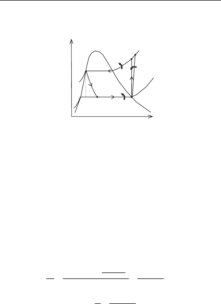
Temperature–entropy diagram of the cycle is given in Figure 4.3.
Q
H
Q
L
120 kPa
1
2
3
4
900 kPa
s
T
·
W
·
·
4s
2s
Figure 4.3 Temperature–entropy diagram of vapor-compression refrigeration cycle considered in Example 4.1.
(a) The properties of R-134a are (from Tables B.3–B.5)
P
1
= 120 kPa
x
1
= 1
h
1
= 236.97 kJ/kg
P
2
= 900 kPa
T
2
= 75
◦
C
h
2
= 310.51 kJ/kg
P
3
= 900 kPa
x
3
= 0
h
3
= 101.61 kJ/kg
h
4
= h
3
= 101.61 kJ/kg
The work input and heat removal per unit mass of the refrigerant are
w = h
2
− h
1
= 310.51 − 236.97 = 73.54 kJ/kg
q
L
= h
1
− h
4
= 236.97 − 101.61 = 135.4kJ/kg
The mass flow rate of R-134a is
˙m
R
=
˙
Q
L
q
L
=
(18, 000 Btu/h)
1kW
3412.14 Btu/h
135.4kJ/kg
=
5.275 kW
135.4kJ/kg
= 0.0390 kg/s
(b) The COP of the refrigerator is
COP =
q
L
w
=
135.4kJ/kg
73.54 kJ/kg
= 1.84
(c) If the expansion valve is replaced by an isentropic turbine
P
3
= 900 kPa
x
3
= 0
s
3
= 0.3738 kJ/kg · K