Dinc Ibrahim. Refrigeration systems and applications 2th edition
Подождите немного. Документ загружается.

Heat Pumps 301
3
Inside coil
7
8
6
Vapor
Compressor
1
2
3
Outside coil
4
6
Compressed vapor
Liquid refrigerant
5
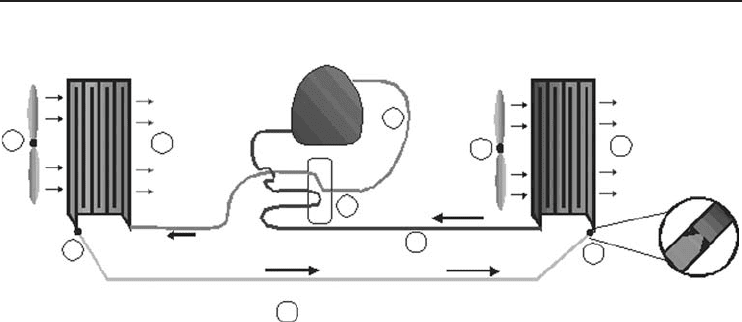
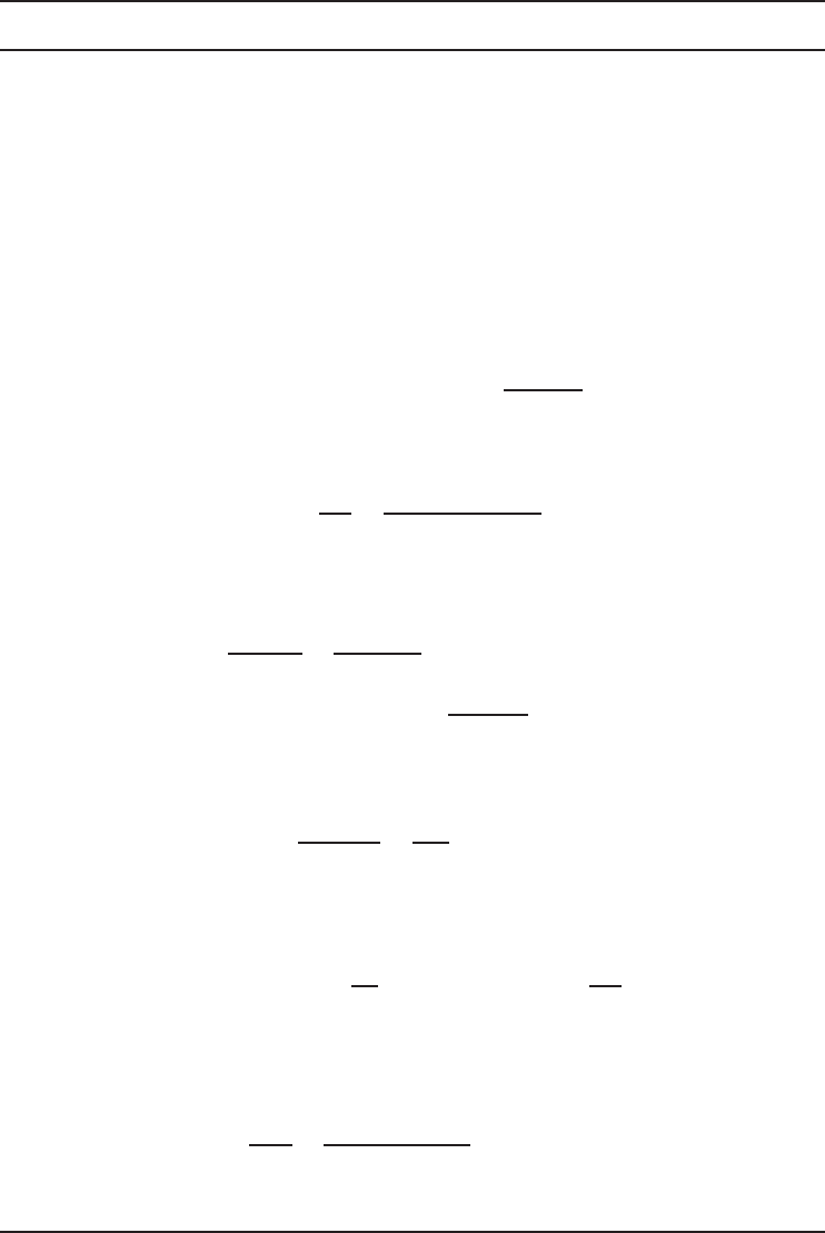
Figure 6.8 A vapor-compression heat pump running for heating (Courtesy of D&H Climate Control).
accomplished by reversing the flow of refrigerant through a device found in heat pumps knows as
a “reversing valve”. This valve is automatically controlled through the thermostat when switched
to heat.
Figure 6.8 shows the heat pump in the heating mode of operation (e.g., in winter the heat
exchanger located outside the house functions as an evaporator, absorbing low-temperature heat
from the environment). Switching the heat pump from the cooling mode to the heating mode
is achieved simply by switching the direction of the refrigerant flow. The difference between
Figures 6.7 and 6.8 is that the reversing valve (2) directs the compressed refrigerant to the inside
coil first. This makes the inside coil the condenser and releases the heat energy (3-4). This heated
air is ducted to the home. The outside coil is used to collect the heat energy (3-7). This now
becomes the evaporator. Both heating and A/C modes do exactly the same thing. They pump
heat from one location to another. In these examples, the heat in the air is moved out of or into
the home.
There is usable heat in outdoor air at temperatures as low as −8.5
◦
C. As the temperature of the
outdoor air decreases, however, the heating capacity of the heat pump diminishes proportionately,
resulting in lower discharge air temperatures at the air registers and gradual cooling of the house.
To supplement the heating capacity of the heat pump, electric resistance heating elements are used,
which automatically engage via the thermostat when this condition occurs.
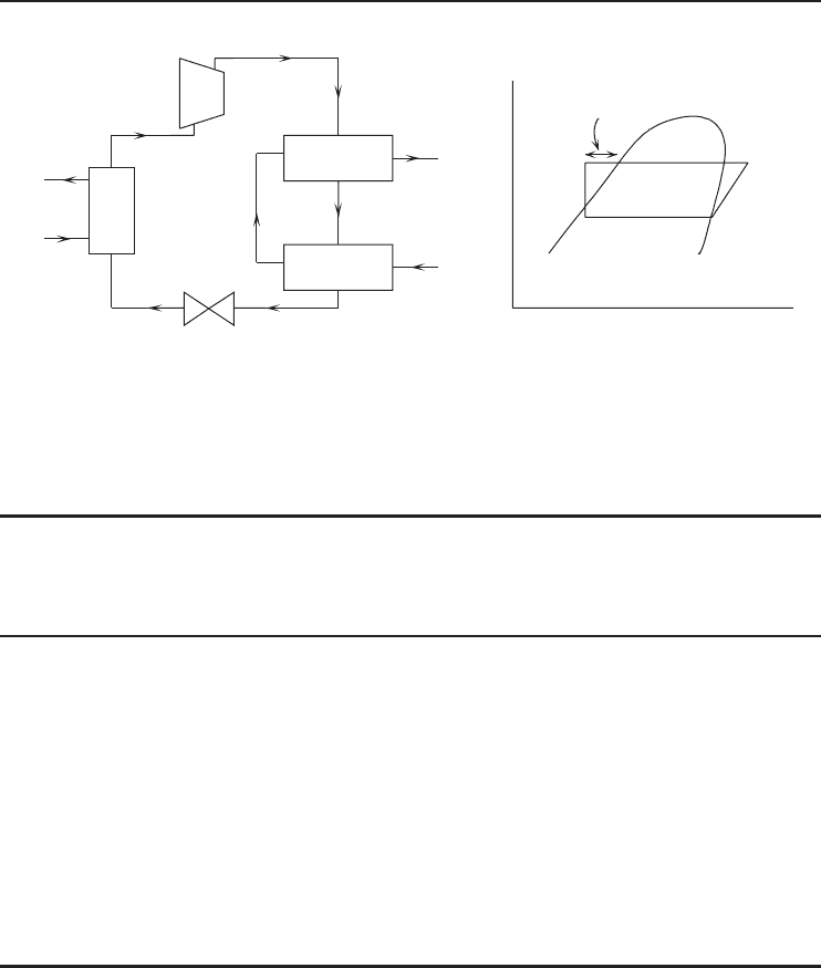
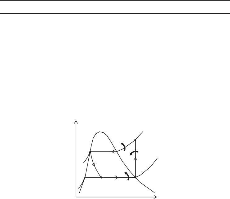
6.10.3 Single-Stage Vapor-Compression Heat Pump with Subcooler
A simple modification can be made to the four-component cycle to make it, in some situa-
tions, considerably more efficient. This is the addition of a refrigerant subcooler, as shown in
Figure 6.9a. This extra heat exchanger extracts heat from the hot liquid refrigerant before it
goes through the expansion valve. This leads to less flash gas formation through the expansion
valve. Hence, the same compressor is doing more useful cooling and heating, with no extra power
consumption (note that the compressor is “unaware” of whether its suction vapors are formed
across the expansion valve or through boiling in the evaporator). Figure 6.9b shows the effect
of subcooling on a Mollier chart. In both cases illustrated, the primary heating is carried out
between 70 and 75
◦
C. In the case of a subcooler the hot refrigerant (80
◦
Cwhenleavingthe
condenser) is cooled to 30
◦
C by a stream of air. This extra free heat can successfully be used
by integrating an air space heating unit with the main hot water system. The financial advantage
is considerable.
302 Refrigeration Systems and Applications
Evaporator
Condenser
Subcooler
Source Sink
1
2
3
45
1
2
3
4
5
log P
h
Subcooling
(a) (b)
Figure 6.9 (a) A single-stage vapor-compression heat pump with subcooler and (b) its log P −h diagram.
Table 6. 8 ARI standard rating conditions for variable capacity compressors and compressor units used in
heat pumps.
Rating
Test Point
Intended Use Suction Dew
Point
Temperature
(
◦
C)
Discharge
Dew Point
Temperature
(
◦
C)
Return Gas
Temperature
(
◦
C)
Capacity Setting
a
A Air source (cooling) 7.2 56.4 18.3 Max.
B Air source (cooling) 7.2 46.1 18.3 Max.
C Air source (cooling and
heating)
7.2 37.8 18.3 Min.
D Air source (heating) –1.1 43.3 10.0 Max.
E Air source (heating) –15.0 35.0 –3.9 Max.
F Air source (cooling) 7.2 26.7 18.3 Min.
G Air source (heating) 1.7 32.2 12.8 Min.
H Water source (cooling and
heating)
7.2 48.9 18.3 Max. and Min.
Ratings based on 35
◦
C temperature surrounding compressor. If air flow across the compressor is used to
determine ratings, it shall be specified by the compressor manufacturer.
a
The maximum and minimum capacity setting is the highest and lowest displacement capacity obtainable by
the compressor or compressor unit.
Source: ARI (2000).
6.10.4 Standard Rating Conditions for Compressors
The standard rating(s) of a compressor or compressor unit used in a heat pump is its compres-
sor rating(s) based on the tests performed at standard rating conditions at the test points from
Table 6.8.

Heat Pumps 303
6.10.5 ARI/ISO Standard 13256-1
This standard covers those heating and cooling systems usually referred to as water source heat
pumps. These electrically driven vapor-compression systems consist of one or more factory-made
matched assemblies which normally include an indoor conditioning coil with air moving means,
a compressor, and a refrigerant-to-liquid (water or brine) heat exchanger. A system may provide
cooling-only, heating-only, or both functions and is typically designed for use within one or more
of the following liquid heat source/sink applications: (i) water-loop heat pump using temperature-
controlled water circulating in a common piping loop, (ii) groundwater heat pump using water
pumped from a well, lake, or stream, and (iii) ground-loop heat pump using brine circulating
through a subsurface piping loop.
These three applications were previously separately covered by ARI Standards 320, 325, and
330. Rating and performance test conditions for ARI/ISO 13256-1 (Ellis, 2001), as compared to the
previous ARI standards, are summarized in Tables 6.9 and 6.10. As can be seen, the differences in
rating test temperatures are relatively minor, and consist mainly of rounding to the Celsius scale and
Table 6. 9 Comparison of ARI and ISO rating test conditions.
Rating Tests Water-Loop Ground-Loop
Heat Pumps Ground-Water Heat Pumps Heat Pumps
ARI/ISO ARI 320 ARI/ISO ARI 325 Hi ARI 325 Lo ARI/ISO ARI 330
Standard cooling:
Air dry bulb,
◦
C
Air wet bulb,
◦
C
Air flow rate, l/s
Liquid full load,
◦
C
Liquid part load,
◦
C
Liquid flow rate, l/s
27
19
per mfr
a
30
30
per mfr
26.7
19.4
per mfr
29.4
23.9
5.6
◦
Crise
27
19
per mfr
15
15
per mfr
26.7
19.4
per mfr
21.1
21.1
per mfr
26.7
19.4
per mfr
10.0
10.0
per mfr
27
19
per mfr
25
20
per mfr
26.7
19.4
per mfr
25.0
21.1
per mfr
Standard heating:
Air dry bulb,
◦
C
Air wet bulb,
◦
C
Air flow rate, l/s
Liquid full load,
◦
C
Liquid part load,
◦
C
Liquid flow rate, l/s
20
15
per mfr
20
20
per mfr
21.1
15.6
std clg
b
21.1
23.9
std clg
20
15
per mfr
10
10
per mfr
21.1
15.6
std clg
21.1
21.1
per mfr
21.1
15.6
std clg
10.0
10.0
per mfr
20
15
per mfr
0
5
per mfr
21.1
15.6
std clg
0.0
5.0
per mfr
External static:
Air, Pa
Liquid, kPa
0
0
25.0–75.0
NA
0
0
25.0–75.0
150.0
25.0–75.0
150.0
0
0
25.0–75.0
50.0
a
per mfr: per manufacturer.
b
std clg: standard catalog.
Source: Ellis (2001).

304 Refrigeration Systems and Applications
Table 6. 10 Comparison of ARI and ISO performance test conditions.
Rating Tests Water-Loop Heat Pumps Ground-Water Heat Pumps Ground-Loop Heat Pumps
ARI/ISO ARI 320 ARI/ISO ARI 325 Hi ARI/ISO ARI 330
Maximum cooling:
Air dry bulb,
◦
C
Air wet bulb,
◦
C
Liquid,
◦
C
32
23
40
35.0
21.7
35.0
32
23
25
35.0
21.7
23.9
32
23
40
35.0
21.7
35.0
Maximum heating:
Air dry bulb,
◦
C
Liquid,
◦
C
27
30
26.7
32.3
27
25
26.7
23.9
27
25
26.7
23.9
Minimum cooling:
Air dry bulb,
◦
C
Air wet bulb,
◦
C
Liquid,
◦
C
21
15
20
19.4
13.9
18.3
21
15
10
NA
NA
NA
21
15
10
26.7
19.4
0.0
Minimum cooling:
Air dry bulb,
◦
C
Liquid,
◦
C
15
15
NA
NA
15
5
15.6
7.2
15
−5
15.6
−3.9
Enclosure sweat:
Air dry bulb,
◦
C
Air wet bulb,
◦
C
Liquid,
◦
C
27
24
20
26.7
23.9
26.7
27
24
10
26.7
23.9
10.0
27
24
10
26.7
23.9
10.0
Source: Ellis (2001).
eliminating the dual rating points for ARI 325. Performance test temperatures vary more, but these
tests are concerned only with verification of proper equipment operation under extreme conditions,
and results are not published as ratings.
The ARI/ISO standard is not design prescriptive and provides a means for manufacturers
to specify unique air and liquid flow rates for both heating and cooling, and for each step
of capacity, in each chosen application. Additionally, the ARI/ISO standard introduces the
concept of “effective power input” to the heat pump, which includes the power input of the
compressor and controls as well as the proportional power input of fans and pumps, whether
internal or external, and whether provided by the manufacturer or not. The power input of
fans and pumps is proportional in that it only includes that power required to transport air
and liquid through the heat pump, and again avoiding design prescription, does not include
arbitrary external static conditions for each application. Unlike the previous ARI standards,
the power input is calculated in a consistent manner, inclusive of fan and pump power, across
all applications.
Heat Pumps 305
(a) (b)
Q
H
Q
L
1
2
3
4
s
T
·
W
·
·
Q
H
Condenser
Evaporator
Compressor
Expansion
valve
Q
L
W
T
L
T
H
1
2
3
4
·
·
·
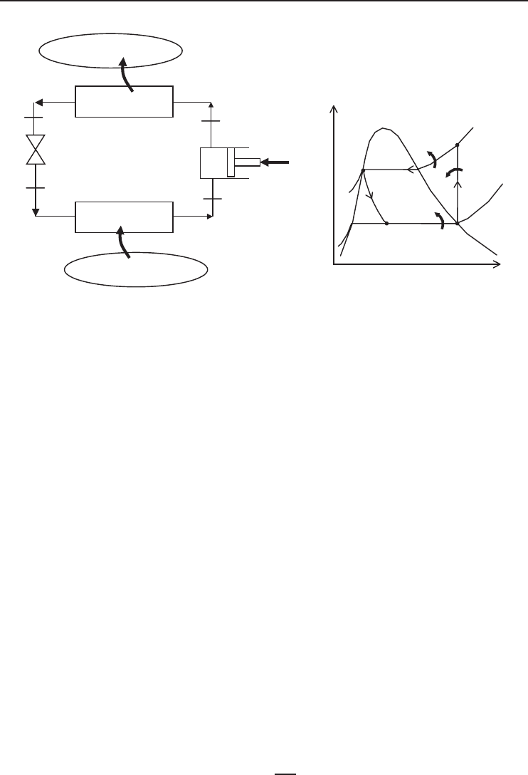
Figure 6.10 A vapor-compression heat pump system for analysis and its temperature–entropy diagram for
the ideal case.
6.11 Energy Analysis of Vapor-Compression Heat Pump Cycle
Energy analysis of a vapor-compression heat pump cycle is very similar to the energy analysis
of vapor-compression refrigeration cycle as given in Chapter 4. Applying conservation of energy
principle to each of the processes of the cycle as shown in Figure 6.10 for steady-flow operation
with negligible kinetic and potential energy changes gives
Compressor:
˙
W =˙m(h
2
− h
1
) (6.7)
Condenser:
˙
Q
H
=˙m(h
2
− h
3
) (6.8)
Expansion valve:
h
3
= h
4
(6.9)
Evaporator:
˙
Q
L
=˙m(h
1
− h
4
) (6.10)
An energy balance on the entire system gives
˙
W +
˙
Q
L
=
˙
Q
H
(6.11)
A heat pump is used to supply heat to the high-temperature space. Therefore, the COP of the
heat pump cycle is defined as
COP =
˙
Q
H
˙
W
(6.12)

306 Refrigeration Systems and Applications
The temperature–entropy diagram of an ideal vapor-compression heat pump cycle is given in
Figure 6.10b. In this cycle, the refrigerant enters the compressor as a saturated vapor. It is com-
pressed isentropically in a compressor; it is cooled and condensed at constant pressure by rejecting
heat to high-temperature medium until it exists as a saturated vapor at the exit of the condenser.
The refrigerant is expanded in an expansion valve during which the enthalpy remains constant: it
is evaporated in the evaporator at constant pressure by absorbing heat from the refrigerated space,
and it leaves the evaporator as a saturated vapor.
6.12 Exergy Analysis of Vapor-Compression Heat Pump Cycle
Figure 6.10 is a schematic of a vapor-compression heat pump cycle operating between a low-
temperature medium (T
L
) and a high-temperature medium (T
H
). The maximum COP of a heat
pump cycle operating between temperature limits of T
L
and T
H
based on the Carnot heat pump
cycle was given in Chapter 1 as
COP
Carnot
=
T
H
T
H
− T
L
=
1
1 − T
L
/T
H
(6.13)
This is the maximum COP that a heat pump operating between T
L
and T
H
can have. Equation 6.13
indicates that a smaller temperature difference between the heat sink and the heat source (T
H
− T
L
)
provides greater heat pump COP.
The aim in an exergy analysis is usually to determine the exergy destructions in each component
of the system and to determine exergy efficiencies. The components with greater exergy destructions
are also those with more potential for improvements. Exergy destruction in a component can be
determined from an exergy balance on the component. It can also be determined by first calculating
the entropy generation and using
˙
Ex
dest
= T
0
˙
S
gen
(6.14)
where T
0
is the dead-state temperature or environment temperature. In a heat pump, T
0
is usu-
ally equal to the temperature of the low-temperature medium T
L
. Exergy destructions and exergy
efficiencies for major components of the cycle are as follows:
Compressor:
˙
Ex
dest,1−2
=
˙
W +
˙
Ex
1
−
˙
Ex
2
=
˙
W −
˙
Ex
12
=
˙
W −˙m
[
h
2
− h
1
− T
0
(s
2
− s
1
)
]
=
˙
W −
˙
W
rev
(6.15)
or
˙
Ex
dest,1−2
= T
0
˙
S
gen,1−2
=˙mT
0
(s
2
− s
1
) (6.16)
η
ex,Comp
=
˙
W
rev
˙
W
= 1 −
˙
Ex
dest,1−2
˙
W
(6.17)
Condenser:
˙
Ex
dest,2−3
=
˙
Ex
2
−
˙
Ex
3
−
˙
Ex
˙
Q
H
=˙m
[
h
2
− h
3
− T
0
(s
2
− s
3
)
]
−
˙
Q
H
1 −
T
0
T
H
(6.18)
or
˙
Ex
dest,2−3
= T
0
˙
S
gen,2−3
=˙mT
0
s
3
− s
2
+
q
H
T
H
(6.19)
η
ex,Cond
=
˙
Ex
˙
Q
H
˙
Ex
2
−
˙
Ex
3
=
˙
Q
H
1 −
T
0
T
H
˙m
[
h
2
− h
3
− T
0
(s
2
− s
3
)
]
= 1 −
˙
Ex
dest
˙
Ex
2
−
˙
Ex
3
(6.20)
Heat Pumps 307
Expansion valve:
˙
Ex
dest,3−4
=
˙
Ex
3
−
˙
Ex
4
=˙m
[
h
3
− h
4
− T
0
(s
3
− s
43
)
]
(6.21)
or
˙
Ex
dest,3−4
= T
0
˙
S
gen,3−4
=˙mT
0
(s
4
− s
3
) (6.22)
η
ex,ExpValve
=
0
˙
Ex
3
−
˙
Ex
4
= 1 −
˙
Ex
dest,3−4
˙
Ex
3
−
˙
Ex
4
= 1 −
˙
Ex
3
−
˙
Ex
4
˙
Ex
3
−
˙
Ex
4
(6.23)
Evaporator:
˙
Ex
dest,4−1
= (
˙
Ex
4
−
˙
Ex
1
) −
˙
Ex
˙
Q
L
(6.24)
=˙m
[
h
4
− h
1
− T
0
(s
4
− s
1
)
]
−
−
˙
Q
L
1 −
T
0
T
L
or
˙
Ex
dest,4−1
= T
0
˙
S
gen,4−1
=˙mT
0
s
1
− s
4
−
q
L
T
L
(6.25)
η
ex,Evap
=
˙
Ex
˙
Q
L
˙
Ex
1
−
˙
Ex
4
=
−
˙
Q
L
1 −
T
0
T
L
˙m
[
h
1
− h
4
− T
0
(s
1
− s
4
)
]
= 1 −
˙
Ex
dest,4−1
˙
Ex
1
−
˙
Ex
4
(6.26)
The total exergy destruction in the cycle can be determined by adding exergy destructions in
each component:
˙
Ex
dest,total
=
˙
Ex
dest,1−2
+
˙
Ex
dest,2−3
+
˙
Ex
dest,3−4
+
˙
Ex
dest,4−1
(6.27)
It can be shown that the total exergy destruction in the cycle can also be expressed as the
difference between the exergy supplied (power input) and the exergy recovered (the exergy of the
heat transferred to the high-temperature medium):
˙
Ex
dest,total
=
˙
W −
˙
Ex
˙
Q
H
(6.28)
where the exergy of the heat transferred to the high-temperature medium is given by
˙
Ex
˙
Q
H
=
˙
Q
H
1 −
T
0
T
H
(6.29)
This is in fact the minimum power input to accomplish the required heating load
˙
Q
H
:
˙
W
min
=
˙
Ex
˙
Q
H
(6.30)
The second-law efficiency (or exergy efficiency) of the cycle is defined as
η
II
=
˙
Ex
˙
Q
H
˙
W
=
˙
W
min
˙
W
= 1 −
˙
Ex
dest,total
˙
W
(6.31)
Substituting
˙
W =
˙
Q
H
/COP and
˙
Ex
˙
Q
H
=
˙
Q
H
(
1 − T
0
/T
H
)
into the second-law efficiency equation,
η
II
=
˙
Ex
˙
Q
H
˙
W
=
˙
Q
H
(
1 − T
0
/T
H
)
˙
Q
H
/COP
=
˙
Q
H
1 −
T
0
T
H
COP
˙
Q
H
=
COP
T
H
/(T
H
− T
L
)
=
COP
COP
Carnot
(6.32)
since T
0
= T
L
. Thus, the second-law efficiency is also equal to the ratio of actual and maximum
COPs for the cycle. This second-law efficiency definition accounts for irreversibilities within the
heat pump since heat transfers with the high- and low-temperature reservoirs are assumed reversible.
308 Refrigeration Systems and Applications
Example 6.1
A heat pump is used to keep a room at 25
◦
C by rejecting heat to an environment at 5
◦
C. The total
heat loss from the room to the environment is estimated to be 45,000 kJ/h and the power input to
the compressor is 4.5 kW. Determine (a) the rate of heat absorbed from the environment in kJ/h, (b)
the COP of the heat pump, (c) the maximum rate of heat supply to the room for the given power
input, and (d) the second-law efficiency of the cycle. (e) Also, determine the minimum power input
for the same heating load and the exergy destruction of the cycle.
Solution
(a) The rate of heat absorbed from the environment in kJ/h is
˙
Q
L
=
˙
Q
H
−
˙
W = 45, 000 kJ/h − (4.5kW)
3600 kJ/h
1kW
= 28,800 kJ/h
(b) The COP of the heat pump is
COP =
˙
Q
H
˙
W
=
(45, 000/3600) kW
4.5kW
= 2.78
(c) The COP of the Carnot cycle operating between the same temperature limits and the maximum
rate of heat supply to the room for the given power input are
COP
Carnot
=
T
H
T
H
− T
L
=
298
298 − 278
= 14.9
˙
Q
H,max
=
˙
W COP
Carnot
= (4.5kW)
3600 kJ/h
1kW
(14.9) = 241,380 kJ/h
(d) The second-law efficiency of the cycle is
η
II
=
COP
COP
Carnot
=
2.78
14.9
= 0.186 = 18.6%
(e) The minimum power input for the same heating load and the exergy destruction of the
cycle are
˙
W
min
=
˙
Ex
˙
Q
H
=
˙
Q
H
1 −
T
0
T
H
= (45, 000 kJ/h)
1 −
278
298
= 3020 kJ/ h
˙
Ex
dest
=
˙
W −
˙
W
min
= (4.5 × 3600) kJ/h − 3020 kJ/h = 13,180 kJ/h
The second-law efficiency may alternatively be determined from
η
II
=
˙
W
min
˙
W
=
3020 kJ/h
(4.5 × 3600) kJ/h
= 0.186 = 18.6%
The result is the same as expected.
Heat Pumps 309
Example 6.2
A heat pump operates on the ideal vapor-compression refrigeration cycle with refrigerant-134a as
the working fluid. The refrigerant evaporates at −20
◦
C and condenses at 1200 kPa. The refrigerant
absorbs heat from ambient air at 4
◦
C and transfers it to a space at 24
◦
C. Determine (a) the work
input and the COP, (b) the exergy destruction in each component of the cycle and the total exergy
destruction in the cycle, (c) the minimum work input and the second-law efficiency of the cycle.
(d) Determine the COP, the minimum power input, the total exergy destruction, and the exergy
efficiency of the cycle if a ground-source heat pump is used with a ground temperature of 18
◦
C.
The evaporating temperature in this case is −6
◦
C. Take everything else the same.
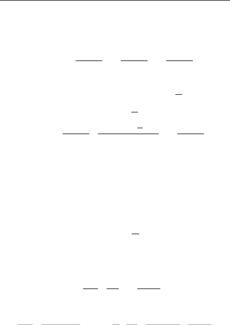
Solution
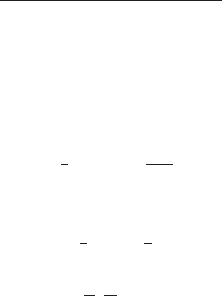
(a) Temperature–entropy diagram of the cycle is given in Figure 6.11.
Q
H
Q
L
−20° C
1
2
3
4
1.2 MPa
s
T
·
W
·
·
Figure 6.11 Temperature–entropy diagram of the cycle considered in Example 6.2.
From the refrigerant-134a tables (Tables B.3 through B.5)
T
1
=−20
◦
C
x
1
= 1
h
1
= 238.41 kJ/kg
s
1
= 0.9456 kJ/kg · K
P
2
= 1200 kPa
s
2
= s
1
h
2
= 284.43 kJ/kg
P
3
= 1200 kPa
x
3
= 0
h
3
= 117.77 kJ/kg
s
3
= 0.4244 kJ/kg · K
h
4
= h
3
= 117.77 kJ/kg
T
4
=−20
◦
C
h
4
= 117.77 kJ/kg
s
4
= 0.4691 kJ/kg · K
q
L
= h
1
− h
4
= 238.41 − 117.77 = 120.6kJ/kg
q
H
= h
2
− h
3
= 284.43 − 117.77 = 166.7kJ/kg
w = h
2
− h
1
= 284.43 − 238.41 = 46.0kJ/kg
310 Refrigeration Systems and Applications
The COP of the cycle is
COP =
q
H
w
=
166.7kJ/kg
46.0kJ/kg
= 3.62
(b) The exergy destruction in each component of the cycle is determined as follows:
Compressor:
s
gen,1−2
= s
2
− s
1
= 0
ex
dest,1−2
= T
0
s
gen,1−2
= 0
Condenser:
s
gen,2−3
= s
3
− s
2
+
q
H
T
H
= (0.4244 − 0.9456) kJ/kg · K +
166.7kJ/kg
297 K
= 0.03991 kJ/kg · K
ex
dest,2−3
= T
0
s
gen,2−3
= (277 K)(0.03991 kJ/kg · K) = 11.06 kJ/kg
Expansion valve:
s
gen,3−4
= s
4
− s
3
= 0.4691 − 0.4244 = 0.04473 kJ/kg · K
ex
dest,3−4
= T
0
s
gen,3−4
= (277 K)(0.04473 kJ/kg · K) = 12.39 kJ/kg
Evaporator:
s
gen,4−1
= s
1
− s
4
−
q
L
T
L
= (0.9456 − 0.4691) kJ/kg · K −
120.6kJ/kg
277 K
= 0.04100 kJ/kg · K
ex
dest,4−1
= T
0
s
gen,4−1
= (277 K)(0.04100 kJ/kg · K) = 11.36 kJ/kg
The total exergy destruction can be determined by adding exergy destructions in
each component:
ex
dest,total
= ex
dest,1−2
+ ex
dest,2−3
+ ex
dest,3−4
+ ex
dest,4−1
= 0 + 11.06 + 12.39 + 11.36 = 34.8kJ/kg
(c) The exergy of the heat transferred to the high-temperature medium is
ex
q
H
= q
H
1 −
T
0
T
H
= (166.7 kJ/kg)
1 −
277
297
= 11.22 kJ/kg
Thus, the minimum work input is
w
min
= ex
q
H
= 11.22 kJ/kg
The second-law efficiency of the cycle is
η
II
=
ex
q
H
w
=
11.22
46.0
= 0.244 = 24.4%
The total exergy destruction may also be determined from
ex
dest,total
= w − ex
q
H
= 46.0 − 11.22 = 34.8kJ/kg
The result is identical as expected.