Dinc Ibrahim. Refrigeration systems and applications 2th edition
Подождите немного. Документ загружается.


Heat Pipes 391
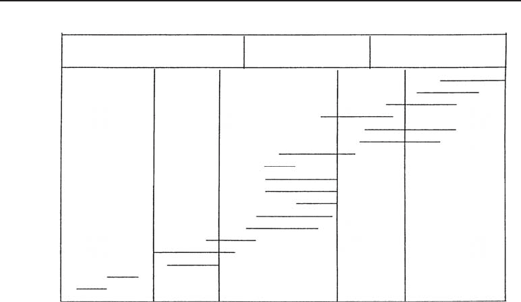
Table 7. 1 Some heat pipe fluids and their temperature ranges.
Medium Melting Point Temperature (
◦
C) Boiling Point Temperature (
◦
C) Application Range (
◦
C)
(at Atmospheric Pressure)
Helium −271 −261 −271 to −269
Nitrogen −210 −196 −203 to −160
Ammonia −78 −33 −60 to 100
Acetone −95 57 0 to 120
Methanol −98 64 10 to 130
Flutec PP2 −50 76 10 to 160
Ethanol –112 78 0 to 130
Water 0 100 30 to 200
Toluene −95 110 50 to 200
Mercury −39 361 250 to 650
Sodium 98 892 600 to 1200
Lithium 179 1340 1000 to 1800
Silver 960 2212 1800 to 2300
Source: Narayanan (2001).
boiling temperatures between 250 and 375 K both cryogenic heat pipes (operating in the 5 to 100 K
temperature range) and liquid-metal heat pipes (operating in the 750 to 5000 K temperature range)
have been developed and used. Figure 7.8 illustrates the possible working temperature ranges for
some of the various heat pipe fluids. In addition to the thermophysical properties of the working
fluid, consideration must be given to the ability of the working fluid, to the wettability of the
working fluid, and to the wick and wall materials. Further criteria for the selection of the working
fluids, including a number of other factors such as liquid and vapor pressure and compatibility of
the materials, are considered.
7.6.3 Selection of Working Fluid
Because the basis for operation of a heat pipe is the vaporization and condensation of the working
fluid, selection of a suitable working fluid is perhaps the most important aspect of the design and
manufacture process. Factors affecting the selection of an appropriate working fluid include
• operating temperature range,
• vapor pressure,
• thermal conductivity,
• compatibility with the wick and case materials, the stability, and
• toxicity.
It should be noted that the theoretical operating temperature range for a given heat pipe is
typically between the critical temperature and triple state of the working fluid. Above the critical
temperature, the working fluid exists in a vapor state and no increase in pressure will force it to
392 Refrigeration Systems and Applications
Increasing
heat
transport
capability
Cryogenic heat pipes Low temperature
heat pipes
High temperature
heat pipes
Ag
Li
Na
K
Cs
Hg
H
2
O
NH
3
CH
3
OH
(CH
3
)CO
C
6
H
6
F-11
F-21
CH
4
O
2
N
2
H
2
N
o
10 50 100 500 1000 5000
Temperature (°K)
Figure 7.8 Temperature ranges of some heat pipe working fluids (Peterson, 1994).
return to a liquid state. As a result, when working fluids are above their critical temperature, the
capillary pumping mechanism provided by the wicking structure ceases to function. Similarly, when
the operating temperature is below the triple state, the working fluid exists in the solid and vapor
states. While some heat transfer may occur due to sublimation, operation in this temperature range
should be avoided (Peterson, 1994).
7.6.4 Wick or Capillary Structure
The concept of utilizing a wicking structure as part of a passive two-phase heat-transfer device
capable of transferring large quantities of heat with a minimal temperature drop was first introduced
by Gaugler (1944).
The wick or capillary structure is porous and made of materials like steel, aluminum, nickel, or
copper in various ranges of pore sizes. They are fabricated using metal foams and, more particularly,
felts, the latter being more frequently used. By varying the pressure on the felt during assembly,
various pore sizes can be produced. By incorporating removable metal mandrels, an arterial structure
can also be molded in the felt.
Fibrous materials, like ceramics, have also been used widely. They generally have smaller pores.
The main disadvantage of ceramic fibers is that they have little stiffness and usually require a
continuous support by a metal mesh. Thus, while the fiber itself may be chemically compatible
with the working fluids, the supporting materials may cause problems. More recently, interest has
turned to carbon fibers as a wick material. Carbon fiber filaments have many fine longitudinal
grooves on their surface, have high capillary pressures, and are chemically stable. Many heat pipes
constructed using carbon fiber wicks seem to show a greater heat transport capability.
The main goal of the wick is to generate capillary pressure to transport the working fluid from
the condenser to the evaporator. It must also be able to distribute the liquid around the evaporator
section to any area where heat is likely to be received by the heat pipe. Often, these two functions
Heat Pipes 393
require wicks of different forms. The selection of the wick for a heat pipe depends on many factors,
several of which are closely linked to the properties of the working fluid.
Note that the maximum capillary head generated by a wick increases with decrease in pore size.
The wick permeability increases with increasing pore size. Another feature of the wick which must
be optimized is its thickness. The heat transport capability of the heat pipe is raised by increasing
the wick thickness. The overall thermal resistance at the evaporator also depends on the conductivity
of the working fluid in the wick. There are some other necessary properties of the wick, namely,
compatibility with the working fluid and wettability.
The two most important properties of a wick are the pore radius and the permeability. The pore
radius determines the pumping pressure that the wick can develop. The permeability determines
the frictional losses of the fluid as it flows through the wick. The most common types of wicks
that are used are as follows (Narayanan, 2001):
• Sintered powder metal. This process will provide high power handling, low temperature gradi-
ents, and high capillary forces for antigravity applications. A complex sintered wick with several
vapor channels and small arteries is used to increase the liquid flow rate. Very tight bends in the
heat pipe can be achieved with this type of structure.
• Grooved tube. The small capillary driving force generated by the axial grooves is adequate for
low-power heat pipes when operated horizontally or with gravity assistance. The tube can be
readily bent. When used in conjunction with screen mesh, the performance can be considerably
enhanced.
• Screen mesh or cable or fiber. This type of wick is used in the majority of the products and
provides readily variable characteristics in terms of power transport and orientation sensitivity,
according to the number of layers and mesh counts used.
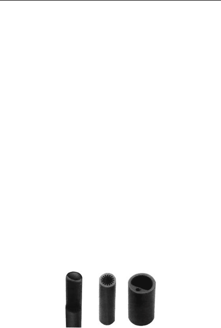
Figure 7.9 shows several heat pipe wick structures. It is important to select the proper wick
structure for your application. The above list is in order of decreasing permeability and decreasing
pore radius. Grooved wicks have a large pore radius and a high permeability; as a result, the pressure
losses are low and the pumping head is also low. Grooved wicks can transfer high heat loads in
a horizontal or gravity-aided position, but cannot transfer large loads against gravity. The powder
metal wicks at the opposite end of the list have small pore radii and relatively low permeability. They
are limited by pressure drops in the horizontal position but can transfer large loads against gravity.
The wicking structure has two functions in heat pipe operation:
• providing the mechanism by which the working fluid is returned from the condenser to the
evaporator and
• ensuring that the working fluid is evenly distributed over the evaporator surface.
Figure 7.9 Wick structures (Garner, 1996) (Reproduced by permission of Flomerics, Inc.).
394 Refrigeration Systems and Applications
Wrapped screen Sintered metal Axial groove
Simple homogeneous
(a)
Current composite
(b)
Slab Pedestal artery Spiral artery Tunnel artery
Monogroove
Advanced designs
(c)
Axial groove
(non-constant
groove width)
Double wall
artery
Channel wick
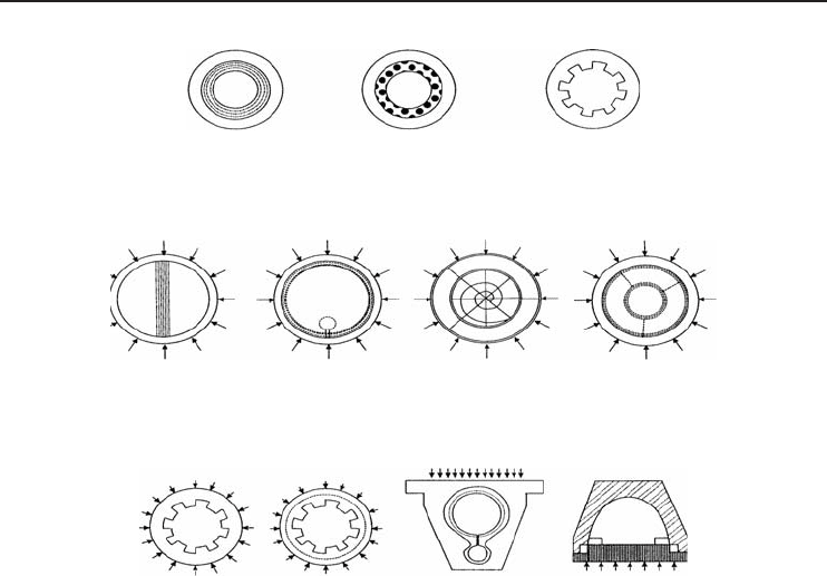
Figure 7.10 Some common heat pipe wicking configurations and their structures. (a) Simple homogeneous,
(b) current composite, and (c) advanced designs (Peterson, 1994).
Figure 7.10 illustrates several common wicking structures presently in use, along with several
more advanced concepts under development. In order to provide a flow path with low flow resistance
through which the liquid can be returned from the condenser to the evaporator, an open porous
structure with a high permeability is desirable. However, to increase the capillary pumping pressure,
a small pore size is necessary. Solutions to this apparent dichotomy can be achieved through the
use of a nonhomogeneous wick made of several different materials or through composite wicking
structures similar to those shown in Figure 7.10b.
The wicking structure has two functions in heat pipe operation: it is both the vehicle and the
mechanism through which the working fluid returns from the condenser to the evaporator and it
ensures that the working fluid is evenly distributed circumferentially over the entire evaporator
surface. Figure 7.10 illustrates several common wicking structures presently in use, along with
several composite and high capacity concepts under development. As shown in Figure 7.10, the
various wicking structures can be divided into three broad categories as follows:
• Homogeneous structures. Homogeneous wicks typically comprise of a single material and
are distributed uniformly along the axial length of the heat pipe. The most common types of
homogeneous wicks include wrapped screen, sintered metal, axially grooved and crescent as
shown in Figure 7.10a.

Heat Pipes 395
• Current composite. In order to provide a flow path with low flow resistance through which
the liquid can be returned from the condenser to the evaporator, an open porous structure with
a high permeability is desirable. However, to increase the capillary pumping pressure, a small
pore size is necessary. Solutions to this apparent dichotomy can be achieved through the use
of a nonhomogeneous wick made of several different materials or through a composite wicking
structure. Composite wicks are typically comprised of a combination of several types or porosities
of materials and/or configurations. Examples of these types of wick structures are illustrated in
Figure 7.10b.
• Advanced designs. Most of these are relatively new (Figure 7.10c) and consist of variations
on the composite wicking structures. Again, the two functions of the wicking structure (i.e.,
circumferential distribution and axial fluid transport) are achieved by different segments of the
capillary structure. The basic design of this advanced capacity configuration consists of two large
axial channels, one for vapor flow and the other for liquid flow. In this type of heat pipe, several
improvements result from the separation of the liquid and vapor channels. First, because the axial
liquid transport can be handled independently from the circumferential distribution, a high heat
transport capacity can be achieved. Second, by separating the two channels, the viscous pressure
drop normally associated with heat pipes in which the liquid and vapor flows occur within the
same channel can be greatly reduced. Third, with the majority of the fluid located in an external
artery, heat transfer in the evaporator and condenser takes place across a relatively thin film of
liquid in the circumferential wall grooves, thereby increasing the heat-transfer coefficient. While
somewhat different in shape, the basic principle of operation of the other advanced designs is the
same: Separate the circumferential distribution and axial liquid flow to maximize the capillary
pumping and reduce the liquid pressure drop.
7.7 Operational Principles of Heat Pipes
Inside the container is a liquid under its own pressure that enters the pores of the capillary material,
wetting all internal surfaces. Applying heat at any point along the surface of the heat pipe causes the
liquid at that point to boil and enter a vapor state. When that happens, the liquid picks up the latent
heat of vaporization. The gas, which then has a higher pressure, moves inside the sealed container
to a colder location where it condenses. Thus, the gas gives up the latent heat of vaporization and
moves heat from the input to the output end of the heat pipe. Heat pipes have an effective thermal
conductivity many thousands of times that of copper. The heat transfer or transport capacity of a
heat pipe is specified by its “Axial Power Rating (APR).” It is the energy moving axially along the
pipe. The larger the heat pipe diameter, the greater is the APR. Similarly, the longer the heat pipe
the lesser is the APR. Heat pipes can be built in almost any size and shape.
Heat pipes transfer heat by the evaporation and condensation of a working fluid. As stated earlier,
a heat pipe is a vacuum-tight vessel which is evacuated and partially backfilled with a working
fluid. As heat is input at the evaporator, fluid is vaporized, creating a pressure gradient in the
pipe. This pressure gradient forces the vapor to flow along the pipe to the cooler section where
it condenses, giving up its latent heat of vaporization. The working fluid is then returned to the
evaporator by capillary forces developed in the porous wick structure or by gravity.
A heat pipe is said to be operating against gravity when the evaporator is located above the con-
denser. In this orientation, the working fluid must be pumped against gravity back to the evaporator.
All heat pipes have wick structures that pump the working fluid back to the evaporator using the
capillary pressure developed in the porous wick. The finer the pore radius of a wick structure,
the higher the heat pipe can operate against gravity. A thermosiphon is similar to a heat pipe, but
has no wick structure and will only operate gravity aided.
A heat pipe (Figure 7.7) consists of a vacuum-tight envelope, a wick structure, and a working
fluid. The heat pipe is evacuated and then backfilled with a small quantity of working fluid, just

396 Refrigeration Systems and Applications
enough to saturate the wick. The atmosphere inside the heat pipe is set by an equilibrium of liquid
and vapor. As heat enters at the evaporator this equilibrium is upset, generating vapor at a slightly
higher pressure. This higher pressure vapor travels to the condenser end where the slightly lower
temperatures cause the vapor to condense, giving up its latent heat of vaporization. The condensed
fluid is then pumped back to the evaporator by the capillary forces developed in the wick structure.
This continuous cycle transfers large quantities of heat with very low thermal gradients. A heat
pipe’s operation is passive, being driven only by the heat that is transferred. This passive operation
results in high reliability and long life.
Both heat pipes and thermosiphons operate on a closed two-phase cycle and utilize the latent
heat of vaporization to transfer heat with very small temperature gradients. However, the operation
of these two devices is significantly different. In a heat pipe, as illustrated earlier, heat added to the
bottom portion of a thermosiphon vaporizes the working fluid. During this phase change process,
the fluid picks up the heat associated with its latent heat of vaporization. Because the vapor in the
evaporator region is at a higher temperature and hence at a higher pressure than the vapor in the
condenser, the vapor rises and flows to the cooler condenser where it gives up the latent heat of
vaporization (buoyancy forces assist this process). Gravitational forces then cause the condensate
film to flow back down the inside of the heat pipe wall where it can again be vaporized. Although
the inside surface of a thermosiphon may occasionally be lined with grooves or a porous structure
to promote return of the condensate to the evaporator or increase the heat-transfer coefficient,
thermosiphons principally rely upon the local gravitational acceleration for the return of the liquid
from the evaporator to the condenser. By definition, then, for proper operation the evaporator of a
thermosiphon must be located below the condenser or dryout of the evaporator will occur.
Alternatively, heat pipes utilize some sort of capillary wicking structure to promote the flow of
liquid from the condenser to the evaporator and as a result can be used in a horizontal orientation,
microgravity environments, or even applications where the capillary structure must “pump” the
liquid against gravity from the evaporator to the condenser. It is this single characteristic – the
dependence of the local gravitational field to promote the flow of the liquid from the condenser to
the evaporator – that differentiates thermosiphons from heat pipes.
7.7.1 Heat Pipe Operating Predictions
Historically, the use of metallic heat sinks has been sufficient to provide the required thermal
management for most electronic cooling applications. However, with the new breed of compact
devices dissipating larger heat loads, the use of metallic heat sinks is sometimes limited because
of the weight and physical size required. Accordingly the use of heat pipes is becoming a solution
of choice.
The performance of natural convection heat sinks is directly dependent on the effective surface
area; more effective surface area results in better performance. A heat pipe embedded into the base
material of a standard aluminum extrusion can reduce the overall temperature difference along the
base material, tending to isothermalize the base material. In essence, the localized heat source is
spread equally along the length of the heat pipe, increasing the overall efficiency of the heat sink.
Although an embedded heat pipe heat sink is slightly more expensive because of the added cost of
the heat pipe, it is an easy method of improving the performance of a marginal extrusion.
A more elegant approach is to design a heat sink that fully utilizes the characteristics of a heat
pipe. Typical extruded heat sinks have limited aspect ratios and thick fins, which result in lower
surface area per length. The material thickness adds unnecessary weight, and, more importantly,
obstructs the cooling air flow. To alleviate the extrusion limits, bonded fin heat sinks have been
developed which allow the use of a tall, thin fin, which optimizes cooling flow. But bonded fin heat
sinks can also be limited by the conduction losses in the base plate for concentrated heat sources.
Heat Pipes 397
A heat pipe used in conjunction with parallel plate fins provides more efficient surface area with
minimum volume demands. This design application is useful when there is not enough physical
volume or airflow above the device to use an extrusion, and allows the designer much latitude
in component arrangement. The heat pipe can transport the heat to a “remote” parallel plate fin
stack that has enough volume to dissipate the heat. Heat pipes can be designed into most electronic
devices for various power levels, and may even allow the use of a natural convection heat sink
(DeHoff and Grubb, 2000).
Predicting or developing an optimum heat pipe thermal solution requires use of theoretical and
empirical relationships, wisdom and design experience, and knowledge of the application design
parameters and system flexibilities. For design concepts and preliminary designs, it can be useful
to have a guideline for heat pipe performance. These are general performance guidelines based
on a “standard” powder metal wick structure. Alternative powders and production techniques are
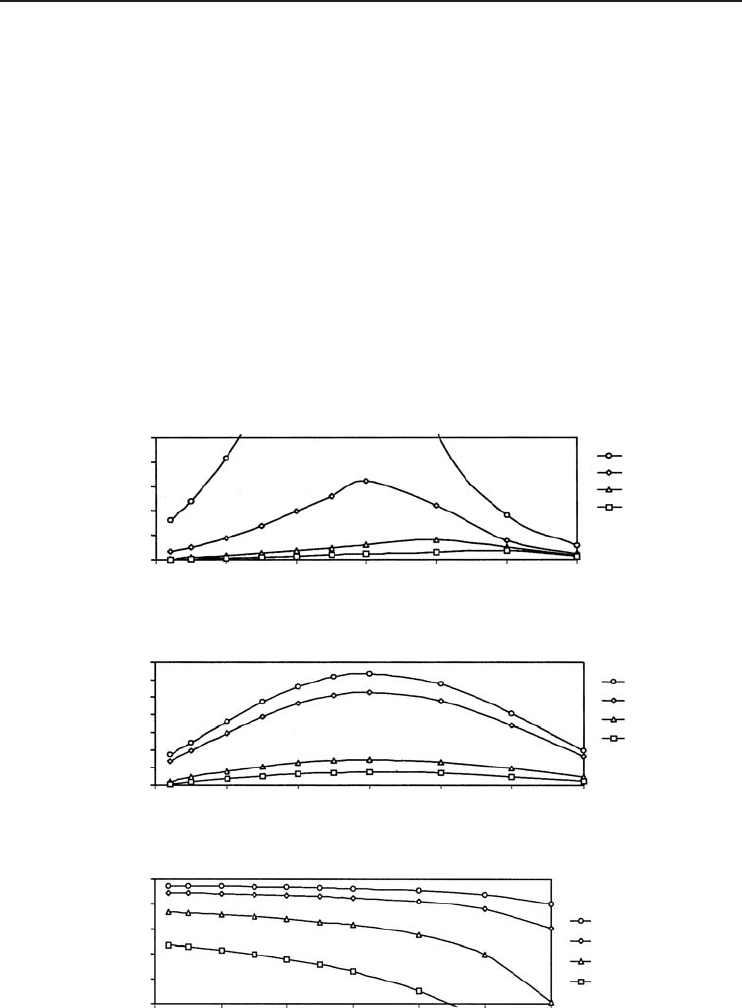
available that may increase the performance by upward of 500%. The above operating limitations
can be summarized to predict heat pipe performances based on three orientation categories and the
performance profiles for such cases are shown in Figure 7.11.
(a)
(b)
(c)
250
200
150
100
50
0
Heat pipe capacity
(Watts)
Heat pipe capacity
(Watts-Inches)
350
300
250
200
150
100
50
0
0 50 100 150 200 250 300
Operating temperature (°C)
0 50 100 150 200 250 300
Operating temperature (°C)
0 50 100 150 200 250 300
Operating temperature (°C)
0.375"
0.25"
4 mm
3 mm
0.375"
0.25"
4 mm
3 mm
Performance factor
1.0
0.8
0.6
0.4
0.2
0.0
1 in.
2 in.
5 in.
10 in.
Figure 7.11 Performance curves: (a) for gravity-aided operation, (b) for horizontal operation, and (c) for
various heights against gravity (Courtesy of Thermacore International, Inc.).

398 Refrigeration Systems and Applications
7.7.1.1 Gravity-Aided Orientation
The evaporator is at a lower elevation than the condenser. The gravity-aided orientation is the most
efficient, since the heat pipe acts as a thermosiphon and gravity will return the condensed fluid to
the evaporator. A sintered powder wick structure may still be needed to handle the heat flux in the
evaporator. Heat pipe operation is typically limited by the flooding limit or the boiling limit (at
elevated temperatures above 175
◦
C). These two limitations are greatly affected by the diameter of
the heat pipe: a larger diameter heat pipe will carry more power. Figure 7.11a can be used as a
guideline for the selection of a “standard” copper–water powder wick heat pipe in the gravity-aided
orientation. The area below each curve is the allowable operating region. For the miniature heat
pipes (3 and 4 mm) use the greater of the “gravity-aided” and “horizontal” curves.
7.7.1.2 Horizontal Orientation
The horizontal orientation relies on the wick structure to provide the capillary pressure to return
the condensed fluid to the evaporator. The heat pipe operation is typically limited by the capillary
limit. This limitation is greatly affected by the diameter of the heat pipe (a larger diameter heat
pipe will carry more power) and the length of the heat pipe (a longer heat pipe will carry less
power). A useful parameter is the effective length (DeHoff and Grubb, 2000):
L
eff
= L
adi
+ 0.5(L
eva
+ L
con
) (7.1)
where L
eff
is the effective length of the heat pipe, m; L
adi
is the length of the adiabatic section of
the heat pipe, m; L
eva
is the length of the evaporator section of the heat pipe, m; and L
con
is the
length of the adiabatic section of the heat pipe, m.
In conjunction with this, Figure 7.11b can be used as a guideline for the selection of a “standard”
copper–water powder wick heat pipe in the horizontal orientation. The capacity of a heat pipe can
be determined by taking the appropriate value from the figure in “watt-inches” and dividing by the
effective length. For example, a 0.25 in. OD heat pipe with a total length of 8 in., an evaporator
length of 1 in., and a condenser length of 5 in. operated at 25
◦
C gives an effective length of 5 in.
Therefore the heat pipe can carry 20 W [100 W-in. (from Figure 7.11b)/5 in.].
7.7.1.3 Against Gravity Orientation
The evaporator is at a higher elevation than the condenser. Heat pipe operation against gravity
orientation relies solely on the wick structure to return the condensed fluid up to the higher evapo-
rator. Again the heat pipe operation is limited by the capillary limit. This orientation is very similar
to the horizontal orientation, except that the effects of gravity must be accounted for. A larger
elevation difference between the evaporator and the condenser results in a lower power capacity.
Figure 7.11c shows the performance factor that can be used as a guideline for the selection of
a “standard” copper–water powder wick heat pipe in the horizontal orientation. The performance
factor must be applied to the capacity obtained from Figure 7.11b. For example, the heat pipe from
the previous example operated 5 in. against gravity would carry 14 W [0.7 (from Figure 7.11c) ×
20 W from above] (DeHoff and Grubb, 2000).
7.7.2 Heat Pipe Arrangement
As mentioned above, the orientation and layout of a heat pipe design are critical. When the design
allows, the heat source should be located below or at the same elevation as the cooling section for
best performance. This orientation allows gravity to aid the capillary action, and results in a greater
Heat Pipes 399
heat-carrying capability. If this orientation is unacceptable, then a sintered powder wick structure
will be necessary. Additionally, heat pipes have the ability to adhere to the physical constraints
of the system, and can be bent around obstructions. For a cylindrical heat pipe, the typical bend
radius is three times the heat pipe diameter. Tighter bend radii are possible, but may reduce the
heat-transfer capability. Since a bend in the heat pipe will have a small impact on performance,
the number of bends should be limited. A good rule of thumb is to assume a 1
◦
C temperature
loss for each 90
◦
bend, if the heat pipe is not operated near one of the limitations. The heat pipe
is also capable of being flattened (a 3-mm diameter heat pipe can be flattened to 2 mm) (DeHoff
and Grubb, 2000). Again, flattening has a minimal effect on performance if the vapor space is not
collapsed or the heat pipe is not operating near a limitation. The heat pipe can conform to the
system space restrictions and can transport the heat from the source to the fin stack or heat sink,
where the heat is effectively dissipated (DeHoff and Grubb, 2000).
7.8 Heat Pipe Performance
The above sections provided an overview of heat pipes and their performance. More important,
though, is the proper use of the heat pipe in a heat sink and the increased heat sink capabilities
that are provided by the utilization of heat pipes. Most applications use a remote fin stack design,
which consists of an aluminum evaporator block (heat input section), the heat pipe (heat transport
section), and aluminum fins (heat dissipation section).
Over the last 10 years, a host of computationally inclined heat pipe investigators in the United
States have been busy modeling heat pipe transient operation. The difficulty of transient heat pipe
modeling can be immense, especially if a simulation of the frozen start-up problem is attempted.
Important mechanisms related to transient heat pipe operation include the transition from free
molecule to continuum flow in the vapor space, the migration of the melt front in capillary structures,
mass transfer between the liquid and vapor regions, compressibility effects and shock formation
in the vapor flow, and the possibility of externally imposed body forces on the working fluid in
its liquid phase. Performance-limiting mechanisms during power transitions in recently proposed
heat pipe systems include evaporator entrainment, freeze-out of the working fluid inventory in the
condenser, evaporator capillary limits, and nucleate boiling departure in the evaporator.
A thermal resistance network, analogous to electrical circuits, is the quickest way to predict
the overall performance of a parallel plate/heat pipe heat sink. The thermal resistance network is
considered a good approach to determine design feasibility (DeHoff and Grubb, 2000). The heat
pipe heat sink can be represented by a resistance network, as shown in Figure 7.12. Although this
network neglects the interface between the device and heat sink, it can easily be added.
Each of the above resistances can be solved to calculate an associated temperature drop using
the Fourier’s law of conduction equation as follows:
˙
Q = kA
T
L
(7.2)
and with the thermal resistance it can be rewritten as
˙
Q =
T
R
(7.3)
Therefore, the temperature drop in the evaporator section (block) can be calculated by the
conduction heat transfer for the evaporator section (R
eva
):
T
eva
=
˙
QL
eva
k
eva
A
eva
(7.4)
400 Refrigeration Systems and Applications
R
eva
R
air
R
fin
R
cv
R
hp
R
int
Figure 7.12 Thermal resistance network for a heat pipe (Courtesy of Thermacore International, Inc.).
The loss associated with the interface between the evaporator block and the heat pipe (R
int
)
can be calculated using the thermal resistance of the interface material, which is typically solder
(R
int
≈ 0.5
◦
C/W · cm
2
) or thermal epoxy (R
int
≈ 1.0
◦
C/W · cm
2
), and the interface area.
T
int
=
˙
QR
int
πD
hp
L
eva
(7.5)
The detailed analysis of heat pipe is rather complex. The total thermal resistance of a heat pipe
is the sum of the resistances due to conduction through the evaporator section wall and wick,
evaporation or boiling, axial vapor flow, condensation, and conduction losses back through the
condenser section wick and wall. A rough guide for a copper/water heat pipe with a powder metal
wick structure is to use 0.2
◦
C/W · cm
2
for the thermal resistance at the evaporator and condenser
(applied over the heat input/output areas) and 0.02
◦
C/W · cm
2
for axial resistance (applied over the
cross-sectional area of the vapor space) in the following equation:
T
hp
=
˙
QR
eva
πD
hp
L
eva
+
˙
QR
ax−hp
πD
2
vs
4
+
˙
QR
con
πD
hp
L
con
(7.6)
The resistance in transferring the heat from the fin to the air (R
cv
) is calculated using the
convection coefficient as follows:
T
cv
=
˙
Q
hA
fin
(7.7)
The conductive losses that are associated with the fin (R
fin
) are governed by the fin efficiency
which is defined as
η
fin
=
tanh(m
fin
L
eff
)
m
fin
L
eff
(7.8)
where
m
fin
=
2h
k
fin
Z
fin
(7.9)
So, the temperature drop in the fin results in
T
fin
= T
cv
(1 − η
fin
) (7.10)
The temperature drop in the air by cooling can be written as
T
air
=
1
2
˙
Q
˙mc
p
(7.11)
The overall performance of the sink is the sum of the individual temperature drops as follows:
T
total
= T
eva
+ T
int
+ T
hp
+ T
cv
+ T
fin
+ T
air
(7.12)