Ellis,J. Pressure transients in water engineering, A guide to analysis and interpretation of behaviour
Подождите немного. Документ загружается.

electric motor, the shaft connecting the motor and pump and the
impeller of the pump, possibly including entrained liquid.
Power P is rate of working or,
P ¼ dE=dt ¼
1
2
I d!
2
=dt ¼ I! d!=dt ðA10:2aÞ
If speed ! is increasing — that is, the machine is running up to full
speed — then d!=dt is þve and rotational kinetic energy is increasing,
and when d!=dt is ve the machine is decelerating and stored energy is
decreasing. The reduced kinetic energy of rotation is partially trans-
ferred to the liquid being pumped and so pumping is continued for a
time after a pump is switched off or tripped.
Torque T is defined as:
T ¼ P=! ¼ I d!=dt ðA10:2bÞ
and is an alternative to using power as a variable.
172
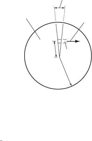
D/2
r
dr
Solid disk of material
Velocity, V
Angle, dq
Fig. A11.1. Definition sketch for deriving moment of inertia
Pressure transients in water engineering
12
Pressure vessels
Pressure vessels form one of the most versatile means of providing surge
protection at pumping stations. A wide range in vessel capacity can be
provided, allowing the vessel or vessels to be optimised to suit any
system. This chapter describes the principles of operation of a pressure
vessel and provides some examples of installations.
All forms of hydraulic transient protection endeavour to limit the
rates of change of flow, acceleration or deceleration within at least
part of a pipeline network. Such flow changes may be introduced to a
system by starting or stopping of pumps. One method of limiting the
rate of acceleration/deceleration of flow is to provide some means of
augmenting flow into the pipeline. This is the principle of operation
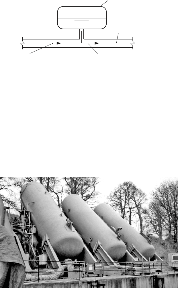
of a pressure vessel when it is installed on the pipeline (Fig. 12.1).
A mass of gas, usually air or nitrogen, is contained in the upper part
of the vessel which is usually cylindrical in shape and installed
either nearly horizontally or vertically. Occasionally a sloping vessel
may be included such as at Ross Priory on Scottish Water’s Loch
Lomond Scheme where four vessels inclined at 458 are used
(Fig. 12.2).
A pressure vessel may be used to improve minimum head conditions
and/or maximum transient pressures.
12.1 Modelling a pressure vessel
Behaviour of a pressure vessel is governed by the response of the gas
mass contained within the upper parts of the vessel. Commonly the
response of the gas is represented by the universal gas law:
p
abs
Vol=T
abs
¼ constant ð12:1Þ
173
where p
abs
is absolute pressure, Vol is the volume of gas and T
abs
is
absolute temperature.
12.1.1 Polytropic relationship
The process of expansion/compression of the gas mass is often replaced
by an approximate relationship of the form:
p
abs
Vol
n
¼ constant ð12:2aÞ
where n is an exponent usually taken to be in the range 1:0 n 1:4
although values outwith this range are possible. Behaviour represented
in this way is termed ‘polytropic’ and a number of technically important
processes can be approximately described by this equation, see for
174
M
Downstream flow augmented by
outflow from vessel |dV/dt| reduced
Flow from upstream decreasing
Pressure vessel
Gas charge
Pipeline
Fig. 12.1. Simple pressure vessel installation
Fig. 12.2. Inclined pressure vessels
Pressure transients in water engineering
example Spalding and Cole (1963). It is possible to find a value of n
which more or less fits a particular set of experimental results. It is
important to note that whereas the ratio of specific heats is a property
of a gas, the empirical exponent n is not and is dependent upon the pro-
cess being considered. n ¼ 1:0 represents an isothermal process with all
changes of pressure and volume taking place at a constant temperature.
This implies that all necessary heat transfers to and from the gas mass
take place concurrently with the changes of pressure and volume.
The value n ¼ 1:4 models an isentropic process without loss or gain
of heat by the gas mass from its surroundings. Neither n ¼ 1:0,
n ¼ 1:4 nor any other constant value of n is true and these values do
not necessarily represent the extremes of n. In the short term during
a transient event there will be insufficient time for heat transfer of
the extent required to maintain a constant temperature within the
gas mass. Over a longer time period, temperature within the vessel
will be restored to the prevailing ambient level as heat is gained or
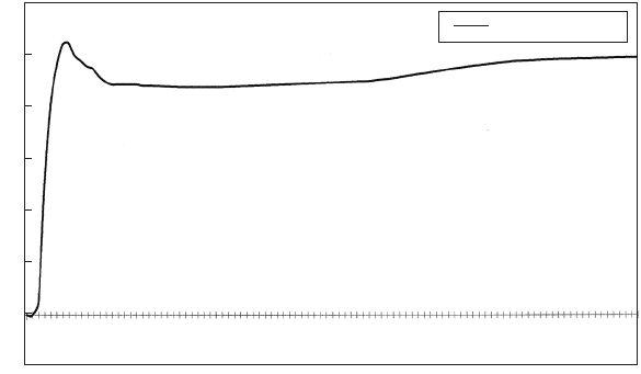
lost to its surroundings. This is illustrated by the recording of water
level within the pressure vessels of the Loch Lomond scheme at Bal-
more (Fig. 12.3) after pumps are started.
During start-up, air is compressed and its temperature rises above
ambient conditions. When steady flow and pressure have been achieved
within about 5 min, the record shows a gradual rise in the vessels’ water
level as the overlying air mass cools. There is no doubt that the
exponent n is not constant during the overall process but use of
175
0
1
2
3
4
5
6
7
8
9
10
11
12
13
14
15
16
17
18
19
20
21
22
23
24
25
1.2
1.0
0.8
0.6
0.4
0.2
0
–0.2
Water level (metres from static level)
Time (min)
Sluice valve level
Auto-sequence start of 24 MGD pumps No. 4 and 5. Surge vessel level from static
Fig. 12.3. Water level in vessel following pump start
Pressure vessels
the polytropic relationship is relatively simple, hence its continued
popularity.
12.1.2 Rational heat transfer (RHT) equation
To address perceived shortcomings of the polytropic equation, Graze
et al. (1976) studied behaviour of an instrumented pressure vessel. Mea-
surements of pressure, air volume and temperature within the vessel
were gathered. These data showed large and important variations in
temperature including the development of freezing temperatures.
They concluded that the observed temperature changes played an
important role in performance of the vessel and that latent heat
could have a significant influence on behaviour. The rational heat
transfer (RHT) equation presented by Graze (1968) was used to
simulate performance of the air charge in the instrumented vessel
with improved predictions over the polytropic equation. The RHT
equation can be written:
dp
abs
=dt þ p
abs
=Vol dVol=dt þð 1Þ=Vol dQ=dt ð12:3Þ
where p
abs
is absolute pressure, Vol is gas volume and dQ=dt is the rate
of heat outflow considered to be entirely due to free convection, defined
as:
dQ=dt per unit surface area ¼ 1:4jtj
1=3
t ð12:4Þ
with t being the differential temperature between the gas mass and
ambient conditions. Research into the influence of latent heat transfer
was considered worthwhile, with the possibility of further improvement
in model predictions resulting.
12.2 Role of a pressure vessel in surge suppression
Suppose a pressure vessel is installed downstream of a pumping station as
illustrated in Fig. 12.4. If the pump is in steady operation the gas mass in
the vessel will be compressed to a volume corresponding to the steady
pumping pressure at the connection point. If the pump is tripped, the pres-
sure downstream of the pump will start to fall and flow from the pump will
diminish. As the effect of falling pressure reaches the vessel then the pres-
sure within the mass of gas will also start to fall, with a corresponding
expansion of gas volume according to the assumed relationship:
Vol ¼ 1=n
p
ðconstant=p
abs
Þð12:2bÞ
176
Pressure transients in water engineering
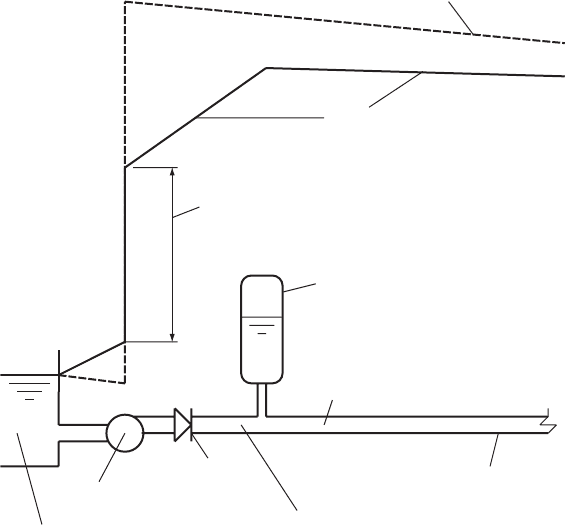
This expansion of gas volume has to be accommodated inside the vessel
by liquid flowing out of the pressure vessel. Flow into the downstream
pipeline is thus augmented by this outflow from the vessel, allowing a
more gradual deceleration of flow at the start of a rising main while a
steeper rate of deceleration is developed upstream of the vessel connec-
tion (Fig. 12.4) than would occur if the vessel were absent. The gradual
expansion of the gas mass also produces a slower fall in pressure at the
start of the main.
12.3 Initial estimation of required pressure vessel volume
12.3.1 Graphical techniques
Determining a suitable size of pressure vessel might start by using one of
the graphical methods of establishing a preliminary volume. Such
methods have been described by a number of investigators including
Graze and Forrest (1974), Thorley and Enever (1979) and Tucker
177
M
Pressure vessel
Check valve
Larger |dV/dt| upstream of vessel connection
Steady pumping hydraulic gradient
Hydraulic gradient shortly after
pumping failure
Head developed by failing pump
shortly after trip
Small |dV/dt| downstream of
vessel connection
Rising main
Suction well or wet well
Failing pump
Fig. 12.4. Instantaneous hydraulic grade line after pump trip
Pressure vessels

and Young (1960). These charts allow an initial assessment of vessel
volume to be made for many of the more common cases.
12.3.2 Simple numerical method
In circumstances where charts may not be available and when a rapid
assessment of vessel parameters is required then approximate equations
can be used. Perhaps the simplest of these equations was described by
Manuel (1970).
Starting from the assumption that the flow downstream of the vessel
decelerates to zero over an interval t ¼ 20L=a and if mean outflow from
the vessel is say half of the initial steady flow Q
o
then this simple
formula for volume abstracted from the vessel can be written:
Volume ¼
1
2
Q
o
t ¼
1
2
Q
o
20L=a ð12:5aÞ
If wavespeed a 1000 m/s for a fairly rigid pipeline then:
Volume
1
2
Q
o
20L=1000 0 :01Q
o
L
12.3.3 More detailed numerical assessment
If a more accurate initial assessment of volume is required, an appendix
to this chapter describes the derivation and use of a set of equations
which allow vessel volume to be estimated. These equations were
derived from use of the rigid column approach.
Equations (A12.5a) and (A12.5b) are for the frictionless case with
n ¼ 1 and n 6¼ respectively.
Vol
m
¼ Vol
p
e
o
=fzð1 h
m
=zÞþh
m
lnðh
m
=zÞg ðA12:5bÞ
Vol
m
¼ Vol
p
e
o
=fz½1 ðh
m
=zÞ
1=n
þ h
m
=ð1 nÞ½ðh
m
=zÞ
ð1=ð1 nÞÞ
1g ðA12:5cÞ
Definition of terms used can be found in the appendix. More compli-
cated equations including the effects of pipeline resistance are also
included in the appendix as equations (A12.9a) and (A12.9b). Also
included in the appendix are illustrations showing how these equations
can be used.
12.3.4 Subsequent investigations and criteria
Subsequently detailed computations would be conducted of pumping
failure to determine more accurate minimum downsurge conditions
178
Pressure transients in water engineering
and the maximum expanded gas volume. To this maximum gas volume
is added a factor of safety in order to determine the gross vessel capacity
necessary.
Fixing minimum transient pressures is of particular importance as far
as treated water pipelines are concerned. Ideally the minimum transient
pressure should remain positive throughout the pipeline system for a
treated water application to avoid risk of contamination, but pressure
may be allowed to fall to a lower level in a raw water or sewage
system. Unfortunately it is a sad fact that in many countries economic
constraints make it difficult to find money for surge suppression, let
alone meet the strict criteria of maintaining positive pressures in treated
water supply pipelines. In such countries, circumstances dictate that
minimum transient pressures become sub-atmospheric with depressing
regularity given the often unreliable state of power supplies.
Having estimated a gas charge for a pressure vessel, more detailed
computations can be carried out. These calculations may commence
from static conditions with pumps being operated in sequence, for
multi-pump installations, to allow time for the hydraulic transient
developed from a pump start to dissipate before the next duty pump
is operated.
12.4 Case study of a sewage pumping system
Consider a sewage pumping system comprising two duty pumps
delivering into parallel mains each around 5 km in length. The pipeline
exiting from the pumping station is DN 600 and downstream of the
vessel connection the pipeline bifurcates into DN 600 and DN 450
mains. When a pump is operated, initially it is much easier for flow to
enter the vessel than to proceed along one of the two parallel mains.
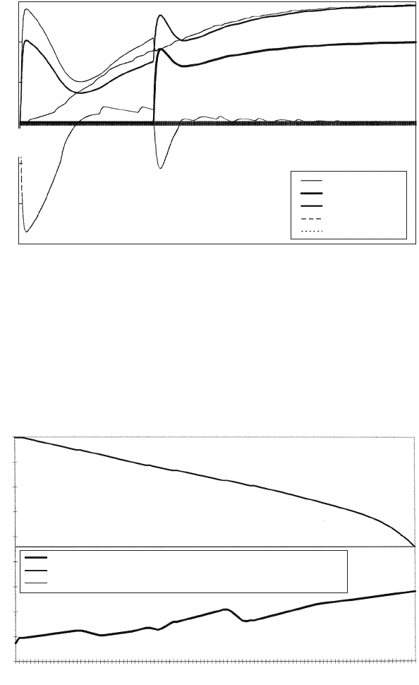
Figure 12.5 shows the velocity variations predicted during start of
two sewage pumps with a 30 s time delay between operation of the
first and second pumps. Outflow from the vessel is taken to be þve.
Velocity in the discharge branch downstream of pump No. 1 increases
to a maximum after about 1 s, with the velocity in the DN 600 pipe
upstream of the vessel connection following a similar trend. Flow into
the vessel, shown as riser velocity, also falls to a minimum, with
inflow being ve. The velocity in the pipelines at chainage 1.5 km
increases much more gradually. As the gas charge becomes pressurised
then inflow to the vessel diminishes and with it the flow from the pump.
The pump is now experiencing a greater downstream head than that
imposed by static conditions. As velocity increases in the downstream
179
Pressure vessels
pipelines the pump output increases once more and some flow leaves
the vessel with pressure in the gas mass falling and the gas volume
expanding. After 30 s the second pump is operated and a further
period of pressurisation of the gas charge in the vessel occurs but to a
lesser extent than when the first pump was operated. After about
180
1.5
1
0.5
0
–0.5
–1
–1.5
Time
(
s
)
Abu Hamour PS 44. Velocities during sequenced pump start
Velocity (m/s)
pump 1
pump 2
u/s of connection
riser
ch 1.5 km
0.045
3.060
6.075
9.090
12.105
15.120
18.135
21.150
24.165
27.180
30.195
33.210
36.225
39.240
42.255
45.270
48.284
51.299
54.314
57.329
60.344
63.359
66.374
69.389
72.403
75.418
78.433
81.448
84.463
87.478
Fig. 12.5. Velocity at a vessel connection during sequenced pump start
0
150
350
550
750
900
1100
1300
1500
1650
1850
2000
2200
2400
2550
2750
2900
3100
3300
3500
3700
3900
4100
4300
4500
4700
4904
Chaina
g
e (m)
Elevation (mQNHD)
i.l. (mQNHD, where QNHD = Qatar National Hydrographic Datum)
h (max.)
h (min.)
Abu Hamour PS 44. Sequenced pump start. Max. and min. head along mains
45
40
35
30
25
20
15
10
5
0
Fig. 12.6. Envelope curves along a rising main after pump start
Pressure transients in water engineering
1
1
2
min essentially steady flow has been established in the pumping
system. It will be noted that the initial discharge from the first pump
exceeds its design steady output. This can have implications with
regard to the short-term power requirements for the pump. The overall
variation of piezometric level along the pumping mains is shown in
Fig. 12.6. Typically a vessel installation will produce a fairly uniform
variation of head along a main. As shown in the figure, inclusion of
the pressure vessel has produced a relatively smooth variation in max-
imum head.
12.5 Worst-case conditions
In attempting to establish a suitable capacity of pressure vessel it is
important to determine the ‘worst case’ as far as the demand on the
vessel is concerned. Typically, for a multi-pump installation, simulta-
neous trip of all duty pumps in steady operation would be examined.
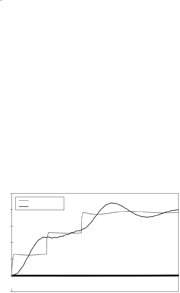
Consider a treated water pumping scheme involving sequenced start
of three pumps at 10 s intervals with a pressure vessel installed down-
stream of the pumps. Figure 12.7 shows the predicted velocity varia-
tions in the DN 700 pipeline just upstream and downstream of the
vessel connection. Upstream of the vessel connection, flow from each
pump rises steeply and then levels off.
Downstream of the vessel connection a more gradual velocity increase
occurs. After the third pump has been operated, output from the pumping
181
Llandinum high-lift pumps. Sequenced start of three pumps
Time (s)
u/s of connection
d/s of connection
Velocity (m/s)
2.5
2
1.5
1
0.5
0
–0.5
0.016
1.568
3.120
4.672
6.224
7.776
9.328
10.880
12.432
13.984
15.536
17.088
18.640
20.192
21.744
23.296
24.848
26.400
27.952
29.504
31.057
32.609
34.160
35.712
37.264
38.816
40.368
41.920
43.472
45.024
46.576
Fig. 12.7. Flow development at a high-lift pumping station
Pressure vessels