Ellis,J. Pressure transients in water engineering, A guide to analysis and interpretation of behaviour
Подождите немного. Документ загружается.

station upstream of the vessel varies only by a modest amount. In contrast,
the flow downstream of the vessel is augmented by flow leaving the pres-
sure vessel after a period when the gas charge has been over-pressurised
following start of the pumps. The maximum flow in the pipeline system
is for a time greater than the design maximum flow. Should a pumping
failure occur during this period of excess flow then the demand on the
vessel may be significantly greater than if pump trip were to take place
from a steady flow condition. Likewise, variations in gas volume within
the pressure vessel will be greater when pumps are tripped at this
maximum flow than if pump failure occurs under steady flow. It is not
suggested that simulations should always include failure from this tran-
sient maximum flow condition but that the possible implications be
borne in mind when choosing a margin of safety for vessel volume.
Uncertainty with regard to the behaviour of the gas charge in the
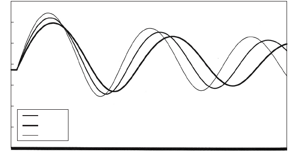
vessel has to be considered when sizing a vessel. Figure 12.8 illustrates
the changing gas volume predicted after all three duty pumps were
tripped from steady maximum discharge, using values of n ¼ 1:0, 1.2
and 1.4. The effect of changing the polytropic coefficient is evident
with the highest value of n producing the maximum vessel volume
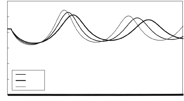
requirement. A similar effect on both maximum and minimum head
is to be seen in Fig. 12.9. Selection of an appropriate vessel volume
has to include some consideration of any limitations in the means of
modelling gas behaviour.
182
Llandinum high-lift pumps
Time (s)
n = 1.2
n = 1.0
n = 1.4
Air volume (m
3
)
0.016
1.552
3.088
4.624
6.160
7.696
9.232
10.768
12.304
13.840
15.376
16.912
18.448
19.984
21.520
23.056
24.592
26.128
27.664
29.200
30.737
32.273
33.808
35.344
36.880
38.416
39.952
41.488
43.024
44.560
46.096
47.631
3.5
3
2.5
2
1.5
1
0.5
0
Fig. 12.8. Computed air volume as a function of polytropic coefficient
Pressure transients in water engineering
Whether starting from an estimated gas charge obtained from one of
the approximate methods, or simply from a first guess, the design pro-
cess usually will involve a series of analyses using alternative gas
charges. As gas charge (static air volume) is increased, the amplitude
of head change reduces with minimum piezometric level increasing
and maximum head decreasing along the pipeline. In many instances,
especially treated water systems, the optimum gas charge will be deter-
mined by the requirement to avoid too low pressures. The appropriate
gas charge is often dictated by conditions somewhere along the pipeline,
say at a local high point on the main. In the present case, minimum
pressure at a point around 800 m from the pumping station was the
critical factor in fixing vessel capacity. To maintain positive pressures
at this location requires a minimum static gas volume of 0.8 m
3
and
to maintain þ0.2 bar g requires a static volume of 1.2 m
3
. Vessel
volume can be quite sensitive to minimum pressure required.
12.6 Reversed flow and refilling a pressure vessel
Having successfully established a vessel gas charge to adequately con-
trol minimum pressures after pumping failure, flow will have come to
rest with a minimum hydraulic gradient along the pipeline. Under the
action of this usually adverse hydraulic gradient, flow will reverse and
accelerate back towards the pressure vessel which will start to refill.
183
Llandinum high-lift pumps
Time
(
s
)
n = 1.2
n = 1.0
n = 1.4
Head (mAOD)
300
250
200
150
100
50
0
0.016
1.552
3.088
4.624
6.160
7.696
9.232
10.768
12.304
13.840
15.376
16.912
18.448
19.984
21.520
23.056
24.592
26.128
27.664
29.200
30.737
32.273
33.808
35.344
36.880
38.416
39.952
41.488
43.024
44.560
46.096
47.631
Fig. 12.9. Predicted head as a function of polytropic coefficient
Pressure vessels
The adverse hydraulic gradient can have a magnitude as large or larger
than the steady pumping gradient and reversed velocities may be sub-
stantial. The strength of the reversed velocity developed will depend
upon the head available and the time over which the gradient acts.
As flow re-enters the pressure vessel the gas mass which had previously
expanded will now begin to be compressed and its internal pressure will
start to increase in accordance with the gas law. As gas pressure rises,
the adverse hydraulic gradient flattens and the rate of acceleration
towards the vessel then decreases. Ultimately pressure in the vessel will
reach a level at which no further acceleration occurs and the reversed
velocity starts to decrease. The gas mass continues to be compressed
until the reversed flow has reached zero. Pressure in the vessel is now at
its peak for this reversed flow event. Where system static head is
modest and the vessel volume is relatively large, the peak pressure after
reversed flow and vessel refilling may not reach steady pumping levels.
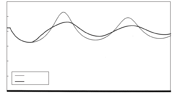
In other circumstances, particularly where static head is large and vessel
volume is more modest, the maximum pressure after reversed flow may
exceed steady pumping level by a considerable margin as illustrated in
Fig. 12.10.
In these schemes where the peak pressure is found to be acceptable
then the gas volume and vessel capacity established to control mini-
mum pressures can be also be considered adequate for the maximum
pressure after flow has refilled the vessel. On the other hand, if
184
Llandinum high-lift pumps
Time
(
s
)
No throttle
DN 150 bp
Head (mAOD)
300
250
200
150
100
50
0
0.016
1.600
3.184
4.768
6.352
7.936
9.520
11.104
12.688
14.272
15.856
17.440
19.024
20.608
22.192
23.776
25.360
26.944
28.528
30.113
31.697
33.281
34.864
36.448
38.032
39.616
41.200
42.784
44.368
45.952
47.535
Fig. 12.10. Head variations showing effects of throttling inflow to vessel
Pressure transients in water engineering
maximum transient pressure is excessive, measures require to be taken
in order to reduce these pressures to within acceptable limits. Two
options present themselves.
(a) Increase the gas volume and vessel size to reduce pressure ampli-
tude generally.
(b) Alternatively, the reversed flow returning to the vessel and which
produces the peak pressure during compression of the gas mass,
can be ‘throttled’ to damp out or reduce the energy of the returning
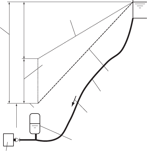
flow as illustrated in Fig. 12.11. The act of throttling inflow to the
vessel after velocity reversal in the pipeline causes head in the main
at the vessel connection to increase in order to overcome the
resistance of the throttle. This reduces the magnitude of the
adverse hydraulic gradient which was responsible for acceleration
of the reversed flow (Fig. 12.11). Magnitude of reversed velocity
is thus limited, and with a smaller return flow the hydraulic level
in the vessel necessary to decelerate this flow is also reduced.
The peak pressure of the return upsurge is thus limited.
185
Pum
p
in
g
station
M
Pressure vessel
Pumping main
Reversed velocity
Piezometric line
without throttling
M
Downstream piezometric level in service reservoir
Piezometric gradient with
throttling at vessel inlet
Total head
available
Head drop
in throttle
Piezometric level in vessel
Fig. 12.11. Sketch showing throttle effect
Pressure vessels
A throttling effect can be achieved in several ways but in all cases the
head drop H achieved by the throttle can be represented as:
H ¼
X
ðK
L
=A
2
ÞQ
2
=ð2gÞð12:6Þ
where K
L
is the loss coefficient of a component, A is the cross-sectional
area of the component and Q is flow rate through the component.
Options for the throttle are as follows.
(a) When a modest amount of throtting is required a differential orifice
(Fig. 12.12(a)) may be an attractive solution as no moving parts are
involved. The amount of resistance offered by the differential
throttle is fixed by its geometry.
(b) A set of tapers (Fig. 12.12(b)), could be used to produce a larger
head loss than with the single differential orifice. This has been
used successfully in a number of applications as described by
Popescu (1985).
(c) A non-return valve could be installed in the vessel connection and
an orifice formed in the valve door (Fig. 12.12(c)). The valve would
be orientated to open during outflow from the vessel. After flow
reversal the valve shuts and reversed flow is forced through the
orifice with attendant head loss. The orifice can be sized to produce
the necessary amount of throtting provided the jet passing through
the orifice does not have excessive velocity. Orifice size fixes the
amount of resistance. Head loss through this arrangement can be
appreciably greater than for the differential orifice.
(d) A more versatile throttle can be arranged using a bypass around a
non-return valve, again placed in the vessel connection so as to
open on outflow (Fig. 12.12(d)). The bypass diameter will usually
be appreciably smaller than for the vessel connection. Various
elements such as a gate valve can be placed in the bypass and set
to a part-open position. Other fixed elements such as orifice
plates can also be installed in the bypass to add extra throttling
where the necessary head drop is not achievable without a very
small opening in the gate valve. The orifices can be used to
remove much of the excess head, leaving the valve to ‘tune’ the
overall throttling effect. Large amounts of head loss can be achieved
using this arrangement.
(e) Linser (2004) described an innovative throttle devised in 1932 by
Thoma (see Linser, 2004). Almost unrestricted flow is allowed in
one direction through a cone shaped connection (Fig. 12.12(e)),
while water is set in centrifugal motion using a spiral casing type
186
Pressure transients in water engineering
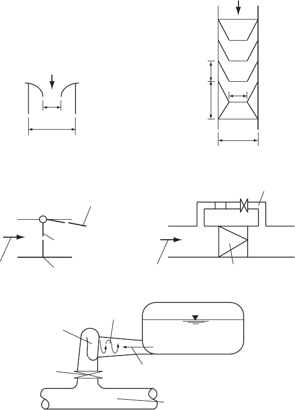
arrangement at inlet to the connection when flow is in the opposite
direction. The device has the advantage of no moving parts. Used
in the Kauner Valley hydroelectric plant to throttle surge tank
flows, resistance in centrifugal motion was 50 times that in the
unrestricted flow direction.
187
Isolating valve
Outflow from vessel
2 × D
o
D
o
Outflow from vessel
D
o
(1.67 – 2.5) × D
o
(1.67 – 2.5) × D
o
(3.34 – 5.0) × D
o
(b)
Orifice may be shaped onto the
vessel base or held between pipe flanges
(a)
Bypass containing valve and
possible orifice plate(s)
Check valve
(d)(c)
Outflow from vessel
Outflow from vessel
Check valve open
during outflow
Orifice in valve door
Check valve closed
during inflow
Rising main
(
e
)
Relatively unrestricted outflow
Pressure vessel
Helicoidal inflow
Spiral casing
Fig. 12.12. Types of throttle
Pressure vessels
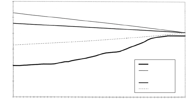
Figure 12.10 demonstrated the influence upon piezometric level at
the vessel connection, of throttling inflow to the pressure vessel using
a check valve and bypass arrangement. The check valve and vessel con-
nection are DN 300 and the bypass is DN 150. Maximum head has
been reduced by about 30 m. The influence on maximum piezometric
levels along the pipeline is shown in Fig. 12.13. Minimum head is
unaffected by the throttle which does not operate during outflow. Mini-
mum air volume within the pressure vessel is influenced by the throttle.
Since maximum pressure is reduced, the air mass is not recompressed by
the returning flow to the same extent. Maximum air volume is not
affected.
Pressure vessels can be made in a wide range of sizes. Smaller
capacities are available off the shelf while larger volumes ranging up
to about 250 m
3
can be custom-made. Probable 250 m
3
is about the
practical upper limit as far as transportation to most sites is concerned.
Where a still larger capacity is necessary this can be made up of several
vessels.
Some pumping stations may have total pressure vessel volumes of
around 1000 m
3
installed, for example at Scottish Water’s Ross Priory
and Balmore pumping stations.
Pumping failure in the presence of a pressure vessel located down-
stream of a high-lift pumping station is usually characterised by rapid
188
0
36.88
73.76
110.64
147.52
184.40
221.28
258.16
295.04
331.92
368.80
405.68
442.56
479.44
516.32
553.20
590.08
626.96
663.84
700.72
737.60
774.48
811.36
848.24
885.12
922.00
Chaina
g
e (m)
i.l. (mAOD)
h
max-no
h
min-no
h
max-150
h
min-150
Llandinum high-lift pumps
Elevation (mAOD)
300
250
200
150
100
50
0
Fig. 12.13. Envelope curves showing throttle effect after a pumping failure
Pressure transients in water engineering
flow reversal and closure of check valves on pump delivery branches.
Once the check valves have closed, conditions on the upstream side
of the valves play no further part in the transient event within the
downstream pumping system. This was the situation for the Llandinum
high-lift pumping system.
12.7 Low-lift systems
Many systems operate with much lower static and pumping heads with
conditions upstream of pump check valves playing a more important
role over a longer time period.
Consider the case of the transmission system from Rifa’a Blending
Station in Bahrain to Hamad Town. The water level in distilled
water storage facilities at Rifa’a may vary from a minimum or bottom
water level (BWL) of 49.15 mBNSD (Bahrain National Survey
Datum) to a maximum or top water level (TWL) at 57.35 mBNSD.
At the Hamad Town tanks, the water level can range from a
BWL ¼42.5 mBNSD to a TWL ¼50.55 mBNSD. Since discharge
into the Hamad Town storage tanks is at TWL, the range in level
within the tanks does not affect hydraulic conditions along the twin
DN 600 DI mains. These mains are around 5.4 km in length and
have an undulating profile with a low point at Buri junction, chainage
2.6 km, from the pumping station.
Each pump has a rated duty of 280 litres/s at a head of 29 m. Pump
speed is 1490 rpm and moment of inertia of each pumpset is 1.7 kg.m
2
.
A maximum of two duty pumps may operate at any time and pumping
failure can occur at any suction well level, thus requiring investigation
of the full range in head conditions. A relatively small pressure vessel
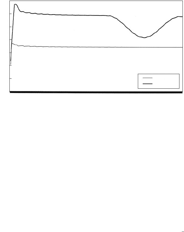
was installed on the delivery side of the pumping station. Figure
12.14 shows the predicted variation of piezometric level, mBNSD, at
Rifa’a for a pumping station blackout with suction tank level at BWL
and at TWL. An initial steep fall in head occurs downstream of the
pumps. This fall is arrested when the discharge level becomes less
than the suction tank level. Flow then continues through the pumping
station and it is this flow which is responsible for maintaining hydraulic
levels. The pressure vessel’s primary function is to attenuate the initial
part of the head drop and it plays only a small part in subsequent events.
When head is at TWL the system is under negative static head and
some flow can continue under gravity. The pumps were essentially aug-
menting the gravity flow. Conditions at TWL become steady after about
1 min. At BWL a small positive static head exists which gradually brings
189
Pressure vessels
flow to rest and produces a modest reversed velocity. This flow reversal
produces the small rise in piezometric level, peaking after about 215 s as
shown in Fig. 12.14.
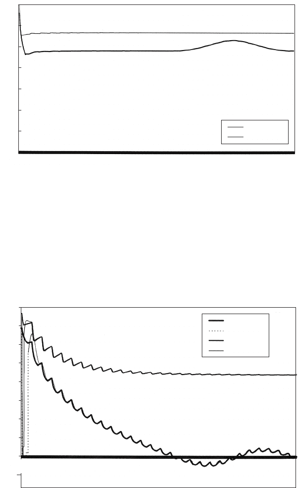
Continuing flow through the pumping station plays an important role
in minimising the required vessel capacity. Figure 12.15 shows the
190
0.090
8.910
17.730
26.550
35.370
44.190
53.010
61.830
70.650
79.469
88.289
97.109
105.928
114.748
123.568
132.387
141.207
150.027
158.846
167.666
176.486
185.305
194.125
202.944
211.764
220.584
229.403
238.223
247.043
255.862
264.682
70
60
50
40
30
20
10
0
Time
(
s
)
Head (TWL)
Head (BWL)
Rifa'a/Hamad Town. Head variations at PS
Head (mBNSD)
Fig. 12.14. Head variations in a low-lift system after pump trip
Time
(
s
)
d/s (BWL)
u/s (BWL)
d/s (TWL)
u/s (TWL)
Rifa'a/Hamad Town. Velocity variations
Velocity (m/s)
1.6
1.4
1.2
1.0
0.8
0.6
0.4
0.2
0
–0.2
0.090
8.910
17.730
26.550
35.370
44.190
53.010
61.830
70.650
79.469
88.289
97.109
105.928
114.748
123.568
132.387
141.207
150.027
158.846
167.666
176.486
185.305
194.125
202.944
211.764
220.584
229.403
238.223
247.043
255.862
264.682
Fig. 12.15. Velocity variations in a low-lift system after pump trip
Pressure transients in water engineering
changing velocity upstream and downstream of the pressure vessel
connection after the pumping failure at time ¼1 s. After pumps are
tripped, velocity falls sharply and check valves close. Downstream of
the vessel connection, velocity changes much more slowly as the
vessel starts to supply water to the pipeline system. When the piezo-
metric level downstream of the check valves becomes less than the
suction tank level, the check valves reopen and flow through the pump-
ing station is re-established with flows upstream and downstream of the
vessel’s connection becoming essentially the same after a relatively
short time. This indicates that the vessel is no longer supplying water
to the system. With a high suction tank level and negative static
head, a gravity flow is established. With lower tank levels and positive
static head, velocity gradually decelerates, with flow reversing after 2
1
2
min at BWL. The check valves now close. A small reversed flow
occurs and a modest repressurisation of the vessel air charge occurs.
Flow then becomes positive once more and as head falls the check
valves may again reopen.
Air volume variations in the pressure vessel are shown in Fig. 12.16.
After the initial pumping failure, volume expands to a maximum. When
check valves reopen and flow is re-established through the pumping
station, air volume decreases by a modest amount. Under negative
system static head conditions — that is, high suction tank levels
(TWL) — air volume is stabilised by the gravity flow condition. For
191
Time
(
s
)
Vol. (BWL)
Vol. (TWL)
Rifa'a/Hamad Town. Air volume variations
Volume (m
3
)
0.090
8.730
17.370
26.010
34.650
43.290
51.930
60.570
69.210
77.850
86.489
95.129
103.768
112.408
121.048
129.687
138.327
146.967
155.606
164.246
172.886
181.525
190.165
198.805
207.444
216.084
224.724
233.363
242.003
250.643
259.282
267.922
7
6
5
4
3
2
1
0
Fig. 12.16. Air volumes in low-lift vessels after pump trip
Pressure vessels