Ellis,J. Pressure transients in water engineering, A guide to analysis and interpretation of behaviour
Подождите немного. Документ загружается.

pipeline. During the time delay of around 0.06 s before the vessels are
able to respond, the first component of wave has been travelling
along the rising main shown in Fig. 13.4. The resultant effect is a
short-duration pressure pulse which travels back and forth in the
rising main on top of the main surge controlled by the pressure ves-
sels. Should this short-term pressure fluctuation coincide with the
peak or trough of the primary wave, the effect will be to increase or
decrease the maximum or minimum transient pressure based upon
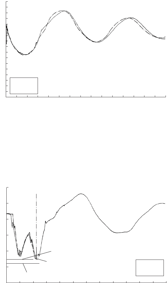
the main wave only. The predicted and observed head variation at
Riding Mill pumping station following simultaneous trip of six duty
pumps, can be seen in Fig. 13.5. Irregularities in head variation are
present on both traces.
Within the Riding Mill pumping main, this effect was responsible for
operation of an air valve at Penn’s Hill (Fig. 13.6), although a
preliminary analysis which neglected the effect of vessel connection
length had suggested that no such valve operation would occur. Both
the observed and simulated head variations at Penn’s Hill show clearly
the presence of higher-frequency components of wave motion. These
waves travel together with the primary wave which is dominated by
the presence of pressure vessels. Where possible, the pressure vessels
should be placed as close as possible to the pumping main to avoid
unnecessary delay in vessel response and to minimise the development
of these secondary wave components.
222
250
200
150
100
50
0
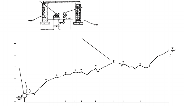
Elevation (mAOD)
River Tyne and
Riding Mill PS
Air vessels
Chaina
g
e (m)
Penn’s Hill
Typical arrangement of
anti-vacuum valve
Anti-vacuum valve
Triple air valve cluster
Letch House tank
Elevation = 223 mAOD
0 930 1400 1760 2160 2455 3050 3815 4230 4865 6207
P
16.5 m
Varies
Fig. 13.4. Rising main pipeline profile
Pressure transients in water engineering
A good-sized connection to the vessel is also desirable to avoid
excessive head loss during outflow thus ensuring the most effective
response from the air chamber. It may be desirable to install a ‘swept’
tee to minimise head loss as flow enters the rising main.
For maximum effect a pressure vessel should be placed as low as
possible. Where static head is low then the difference in level from
223
0 10 20 30 40 50 60 70 80 90 100 110 120 130 140 15
0
Elevation (mAOD)
Time (s)
Observed
Predicted
6 pump trip record at Riding Mill PS
n = 1.4
a = 900 m/s
K = 85
320
300
280
260
240
220
200
180
160
140
120
100
80
60
40
20
0
Fig. 13.5. Head variations at Riding Mill — 6 pump trip
Air valve/anti-vacuum valve operation
0 10 20 30 40 50 60 70 80 90 100 110 120
Recording failure
Predicted
Observed
?60
?40
?20
?00
?80
?60
Elevation (mAOD)
6 pump trip record at Penn’s Hill
Time (s)
n = 1.4
a = 900 m/s
K = 85
Pipeline elevation
Air valve elevation
Fig. 13.6. Head variations at Penn’s Hill — 6 pump trip
Further aspe cts of pressure vessels
the pipeline to the centreline of the vessel may be quite significant. The
smaller the difference in level from the vessel centreline to the down-
stream discharge level the larger will be the required vessel volume.
In systems of low static it is important to employ a realistic assessment
of vessel elevations if a possible underestimation of vessel volume is to
be avoided.
It has been said that the function of the pressure vessel is to limit
changing head or pressure along the rising main. This leaves the rela-
tively short stretch of pipeline between the suction well upstream of
the pump and the connection with the pressure vessel to be considered.
The function of the pressure vessel is to sustain pressure at the vessel
connection and along the rising main. However, on the downstream
side of a failing pump, pressure can fall relatively quickly and a steep
adverse hydraulic gradient can be established within this relatively
short section of pipeline between the pump and the vessel connection
where pressure is being maintained at a relatively high level (Fig. 12.4).
Compared with the situation without a pressure vessel, jdV=dtj
downstream of the vessel is reduced while jdV=dtj upstream of the
vessel is increased.
Flow will tend to reverse more quickly upstream of the vessel connec-
tion than if the vessel were not included. This has important implica-
tions with respect to closure of the check valve downstream of the
pump and will be considered in greater detail when discussing check
valves in Chapters 20 and 21. It may be noted that siting of the
vessel close to the pumps will tend to aggravate check valve closure
conditions and if practical the vessel should be moved further down-
stream rather then being say teed off a manifold directly opposite the
pump branch connections (Fig. 13.7).
224
Discharge manifold
Suction well
Pumps
Check valves
To rising main
Pressure vessel
Less desirable vessel locations
Preferred vessel location
Fig. 13.7. Pressure vessel locations
Pressure transients in water engineering
The pressure vessel does not suppress the transient at its source as
does the flywheel, but rather the transient is developed at the pump
and the vessel acts to suppress its effects to an acceptable extent as
the pressure wave enters a downstream pipeline for instance. As
described, the positioning of the vessel and configuration of its con-
nection can influence the effectiveness of response.
13.5 Installation with air valves
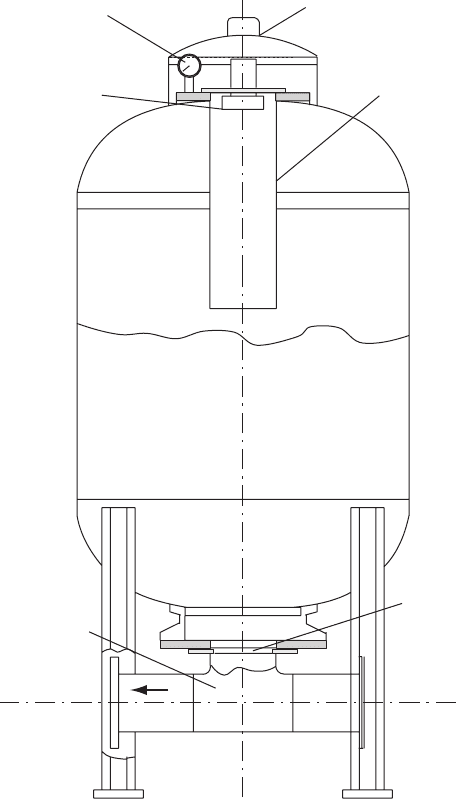
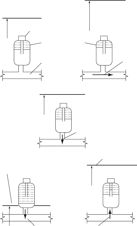
Figure 13.8 shows an hybrid form of vessel incorporating some of
the attributes of a conventional installation but with an air valve
arrangement as a means of replenishing the air charge. In a typical
example the chamber is fitted with a ‘dip-tube’ which extends down-
wards from the air valve connection on top of the vessel, to about
the mid-height of the tank. The lower end of the tube is open. Figure
13.9 illustrates the normal sequence of operation of this protection
device when installed downstream of a pumping station.
(a) At static, the air valve is closed and the tube is filled with liquid. A
charge of air is enclosed in the upper part of the vessel above the
lower end of the tube and under the static pressure head.
(b) While pumping, the air valve remains closed with the tube liquid-
filled as before. The air charge is compressed under the pumping
head in the top of the vessel.
(c) When head starts to fall after a pumping failure, the air mass starts
to expand, releasing liquid into the rising main thus suppressing the
transient head drop in the main. Thus this vessel acts in the same
manner as a conventional pressure vessel at this stage. The dip-tube
still remains liquid-filled at this time.
(d) After a time when head has fallen to the air valve operating level,
the valve will open to allow air to flow into the tube and finally into
the vessel itself. This air flow augments the expanded air volume
already within the vessel. Operation of the air valve largely stabi-
lises head at the vessel and the continued flow of liquid out of
the chamber is essentially balanced by air entering the tank via
the air valve.
(e) After flow reversal has occurred, head starts to rise at the vessel
with air flowing out of the air valve and liquid entering the
vessel. When liquid level reaches the lower end of the dip-tube
the air mass contained in the vessel outside the tube is isolated
while the air in the tube exits via the air valve. The air valve
225
Further aspe cts of pressure vessels
shuts when liquid level reaches the top of the tube and the air mass
remaining in the vessel is compressed by the return flow in the
vessel.
As the hydraulic transient decays, conditions are gradually restored
to static as in item (a) above; the air charge has been replenished as
necessary by operation of the air valve. For this type of vessel to
226
To
pipeline
Flanged outlet
Interchangeable pipeline
connection DN 100 to DN 400
Central tube
Protective cap
Pressure gauge
Air regulating valve
Fig. 13.8. Vessel with air valve and central tube
Pressure transients in water engineering
function successfully, the transient piezometric level must fall to allow
air valve operation. The pipeline profile must be suitable to allow this to
happen. A vessel of this form provides protection from the moment of
pumping failure and relies on the air valve at a later stage both to
augment the air mass and to top-up the air charge contained in the
chamber. In principle a vessel of this type could be installed at any
appropriate location along a pipeline where hydraulic conditions are
suitable, as it does not rely on a power supply. Some throttling of
227
Steady pumping head
Static head
Air valve (AV) closed
Air charge in vessel
AV closed
Rising main
(a) (b)
(c)
Flow from pump
Head shortly after trip
AV closed
Outflow from vessel
Head rising during reversed flo
w
Air outflow at AVAir inflow at AV
Head approaching minimum
Inflow to vesselOutflow from vessel
(e)(d)
Fig. 13.9. Sequence of operation of a vessel with air valve
Further aspe cts of pressure vessels
inflow to the vessel might also be considered, as in a conventional vessel
connection. Capacity of the vessel should be sufficient to contain the
maximum air volume during the sequence of operation.
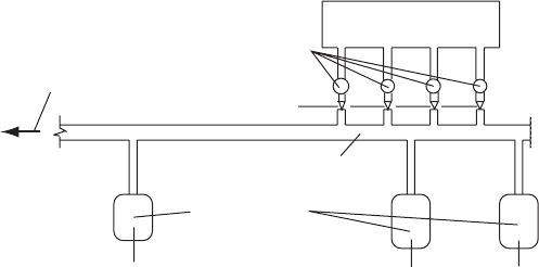
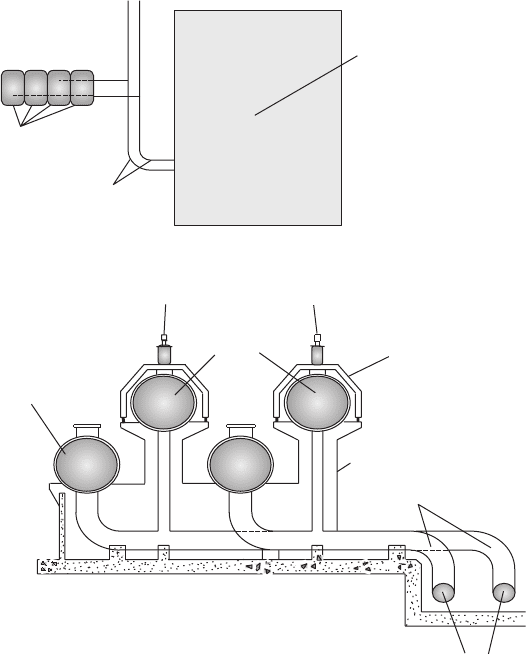
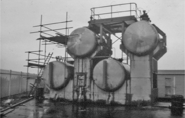
The example shown in Fig. 13.8 can occur in different forms as
illustrated in Fig. 13.10. Twin pumping mains are each fitted with two
horizontally aligned vessels. The upper vessel has three sewage air
valves installed along the top of the horizontal vessel. The lower vessel
is connected to the upper vessel at the base of the riser, extending upwards
to the higher of the vessels (Fig. 13.11). During pumping, the hydraulic
gradient ensures that air is purged from the upper vessel with the air
valves closing on completion of air venting. The air charge in the lower
vessel is compressed but with its air mass remaining in the chamber.
228
Centrifugal pumping station
General layout
Elevation through surge suppression tanks
Lower tanks replenished
with air during downsurge
after pump trip
To r i s i n
g
mains
Vessel connection lines
Concrete tank supports
Air valves Air valves
Upper tanks fitted
with air valves
Mild steel air valve
support frame
Twin GRP rising mains
Surge suppression tanks
Fig. 13.10. Alternative vessel arrangement using air valves
Pressure transients in water engineering
In the event of pump shutdown, pressure falls and the air mass in the
lower chamber expands allowing liquid to flow from the vessel thus
providing a measure of surge protection. Only when hydraulic gradient
has fallen to the operating level of the air valves will these valves open
to allow air inflow which augments surge protection.
229
Fig. 13.11. Vessels with air valves
Further aspe cts of pressure vessels
14
Surge tanks and related
structures
These devices are chambers usually open to the atmosphere, although
pressurised versions have been known. Analysis of a pressurised surge
tank follows the same process as that for a pressure vessel. The simplest
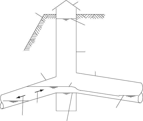
type of surge tank will be a vertical cylinder either above ground
or below ground as at Strathblane on the Loch Lomond Scheme
(Fig. 14.1). There will also be a connection to the pipeline or tunnel
system. Often surge tanks will be of considerable capacity, particularly
where these are used to suppress transients occurring in hydroelectric
power systems. Small surge chambers are also found in water supply
systems where there is a need to control pressure fluctuations.
14.1 Purpose of a surge tank
As with all forms of surge alleviation, the surge chamber is intended to
reduce the rates of change of velocity which would otherwise occur if
the chamber were not present. The presence of a free water surface has
the effect of producing a strong reflection of a pressure wave much
like the reflection from a reservoir. By providing a source of water and a
means of storing water, the tank is a pressure-relieving mechanism. In
the case of flow deceleration in a pipeline downstream of the surge tank
connection, water from an upstream pipeline will be diverted into the
chamber thus avoiding the need for the same rate of flow deceleration
in the upstream line. Likewise, when flow is accelerating in the down-
stream line the chamber supplies water to the downstream main avoiding
the requirement for the upstream line to supply flow to the downstream
system at the same rate. By reducing the rates of acceleration and
deceleration in the upstream conduit, pressure surging upstream of
the surge tank connection can be correspondingly lessened.
230
There are many instances where a tank or chamber is included,
whose function is not that of a surge tank but whose response to and
effect upon hydraulic transients can be analysed using the same tech-
niques as for a surge chamber.
The suitability of a site for this type of installation depends upon the
level of the maximum piezometric line relative to the ground surface —
that is, maximum water level in the chamber is coincident with piezo-
metric level.
Analysis often has to take account of complexities of shape, especially
where the chamber is below ground, often including galleries or a sur-
face pond in place of an upper gallery as at Clachan HEP station
(Fig. 14.2). Galleries, both upper and lower, effectively concentrate
the chamber volume at these levels where it will be most effective
rather in the manner of an RSJ section where area is concentrated at
a distance from the axis. By having a more modest shaft section, the
water level will rise and fall in the shaft more rapidly than if the area
of chamber was constant with changing water level. This means that
an effective hydraulic gradient necessary for acceleration and decelera-
tion of flow is attained more quickly with a smaller shaft cross-section.
231
Pumping flow
Reversed flow in main while
pressure vessels and
feeder tanks refillin
g
Static level in shaft = 68.58 mAOD
Tunnel water level maintained
by throttle valve
downstream = 67.67 mAOD
M
M
M
M
M
Pumping level
1524 j steel pumping main
2134 j tunnel
Surge shaft at north portal
of Balmore tunnel
TWL = 76.81 mAOD
(pumps at Ross Priory tripped)
Cap
Ground level
Fig. 14.1. Simple surge shaft between pumping main and gravity flow tunnel
Surge tanks and related structures