FitzGerald J., Dennis A., Durcikova A. Business Data Communications and Networking
Подождите немного. Документ загружается.


8.4 PACKET-SWITCHED NETWORKS 285
Currently, Ethernet services offer CIR speeds of 1 Mbps to 40 Gbps, in 1-Mbps
increments at a lower cost than traditional packet-switched networks. Because this is an
emerging technology, we should see many changes in the next few years.
8.4.5 Multi-Protocol Label Switching
Multi-protocol label switching (MPLS) is another relatively new WAN technology that
has the potential to dramatically change WAN services. MPLS is designed to work with a
variety of commonly used layer-2 protocols. It is sometimes called a layer-2.5 technology
because it inserts 4-byte header that contains its own information between the layer-2
frame and the layer-3 IP packet.
With MPLS, the customer connects to the common carrier’s network using any
common layer-2 service (e.g., T carrier, SONET, ATM, frame relay, Ethernet). The
carrier’s switch at the network entry point examines the incoming frame and converts
the incoming layer-2 or layer-3 address into an MPLS address label. This label and
some other control information (e.g., quality of service) form the MPLS header, which is
inserted into the layer-2 frame for transmission inside the carrier’s network. The carrier
can use the same layer-2 protocol inside its network as the customer, or it can use
something different; for example, the customer could connect to the MPLS network
using frame relay, but the carrier could use SONET inside its network.
The address in MPLS label is used to move through the frame through the carrier
network until it reaches the edge of the network at the customer’s destination. The
MPLS switch at this exit point removes the MPLS header and delivers the packet into
8.3 MPLS AT CISCO
MANAGEMENT
FOCUS
For years, Cisco Systems Inc. had supported its
Europe/Middle East/Africa (EMEA) offices using
ATM with a series of star networks connected
to stars (called a hub-and-spoke design). The
WAN core was three offices (London, Amster-
dam, and Brussels) connected to each other in a
full mesh using ATM OC-3 circuits. Each of these
three offices was the center of a star network that
connected to three other secondary star networks
and 10 major sites (9 stars and 30 major sites in
total). The 9 secondary stars connected a total of
85 other offices.
The network was at capacity and any time one
of the three core offices (or one of the hubs of
the secondary stars) needed to be taken down
for maintenance, it shut down a major part of
the network. Worse still, it looked like the London
office would need to move to a new building,
which meant significant rewiring of the network.
Cisco chose to implement a full mesh MPLS
network to provide greater capacity and better
flexibility. Each office is connected into the MPLS
carrier’s cloud with two separate MPLS circuits
that are laid in physically separate routes to
provide better reliability in case a circuit is acci-
dentally cut. Each of the two circuits is sized for the
needs of the specific office, ranging from 64 Kbps
up to 45 Mbps. Since the three core offices no
longer route traffic for the entire network, they
don’t need as much network capacity as they did
with the hub and spoke design. The new network
has significantly increased capacity, reliability and
flexibility, while keeping costs about the same.
SOURCE: ‘‘How Cisco IT in Europe Migrated to
MPLS VPN WAN,’’ Cisco IT Case Study, Cisco, 2007.

286 CHAPTER 8 WIDE AREA NETWORKS
the customer’s network using whatever layer-2 protocol the customer has used to connect
into the carrier’s network at this point (e.g., frame, T1).
One advantage of MPLS is that it operates faster than traditional routing. There-
fore, MPLS-based networks operate slightly faster than other packet services. A second
advantage is that common carriers in the United States and Canada typically have a dif-
ferent way of charging for MPLS services than for other packet services, so it is common
to use a full mesh design in which every location is connected to every other location.
Packets take fewer hops and thus less time to reach their destinations.
8.5 VIRTUAL PRIVATE NETWORKS
A virtual private network (VPN) provides the equivalent of a private packet-switched
network over the public Internet.
3
It involves establishing a series of PVCs that run
over the Internet so that the network acts like a set of dedicated circuits over a private
packet network.
8.5.1 Basic Architecture
With a VPN, you first lease an Internet connection at whatever access rate and access
technology you choose for each location you want to connect. For example, you might
lease a T1 circuit from a common carrier that runs from your office to your Internet
Service Provider (ISP). You pay the common carrier for the circuit and the ISP for
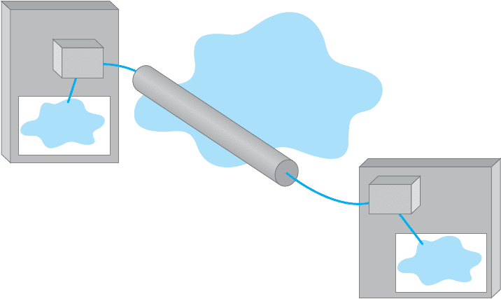
Internet access. Then you connect a VPN gateway (a specially designed router or switch)
to each Internet access circuit to provide access from your networks to the VPN. The
VPN gateways enable you to create PVCs through the Internet that are called tunnels
(Figure 8.10).
The VPN gateway at the sender takes the outgoing packet and encapsulates it with
a protocol that is used to move it through the tunnel to the VPN gateway on the other
side. The VPN gateway at the receiver strips off the VPN packet and delivers the packet
to the destination network. The VPN is transparent to the users; it appears as though a
traditional packet-switched network PVC is in use. The VPN is also transparent to the
ISP and the Internet as a whole; there is simply a stream of Internet packets moving
across the Internet. VPN software is commonly used on home computers or laptops to
provide the same secure tunnels to people working from offsite.
VPNs operate either at layer 2 or layer 3. A layer-2 VPN uses the layer-2 packet
(e.g., Ethernet) to select the VPN tunnel and encapsulates the entire packet, starting with
the layer-2 packet. Layer-2 tunneling protocol (L2TP) is an example of a layer-2 VPN. A
layer-3 VPN uses the layer-3 packet (e.g., IP) to select the VPN tunnel and encapsulates
the entire packet, starting with the layer-3 packet; it discards the incoming layer-2 packet
3
Some common carriers and third-party vendors are now providing VPN services that use their own networks
rather than the Internet. These networks offer an additional measure of security because in addition to flowing
through the carrier’s private network, they provide the same security benefits as VPN’s on the public Internet.
In the interest of simplicity, we will focus on Internet-based VPN services.
8.5 VIRTUAL PRIVATE NETWORKS 287
Internet
Office
VPN
Gateway
VPN Tunnel
Backbone
Office
Backbone
VPN
Gateway
FIGURE 8.10 A virtual private network (VPN). ISP = Internet service provider
and generates an entirely new layer-2 packet at the destination. IPSec is an example of
a layer-3 VPN.
The primary advantages of VPNs are low cost and flexibility. Because they use
the Internet to carry messages, the major cost is Internet access, which is inexpen-
sive compared with the cost of circuit-switched services, dedicated-circuit services, and
packet-switched services from a common carrier. Likewise, anywhere you can establish
Internet service, you can quickly put in a VPN.
There are two important disadvantages. First, traffic on the Internet is unpredictable.
Sometimes packets travel quickly, but at other times, they take a long while to reach their
destination. Although some VPN vendors advertise QoS capabilities, these apply only in
the VPN devices themselves; on the Internet, a packet is a packet. Second, because the
data travel on the Internet, security is always a concern. Most VPN networks encrypt the
packet at the source VPN device before it enters the Internet and decrypt the packet at
the destination VPN device. (See Chapter 10 for more on encryption.)
8.5.2 VPN Types
Three types of VPNs are in common use: intranet VPN, extranet VPN, and access VPN.
An intranet VPN provides virtual circuits between organization offices over the Internet.
Figure 8.10 illustrates an intranet VPN. Each location has a VPN gateway that connects
the location to another location through the Internet.
An extranet VPN is the same as an intranet VPN, except that the VPN connects
several different organizations, often customers and suppliers, over the Internet.
An access VPN enables employees to access an organization’s networks from a
remote location. Employees have access to the network and all the resources on it in the
288 CHAPTER 8 WIDE AREA NETWORKS
ISP
Internet
PPP IP UDP ESP IP TCP HTTP
PPP IP UDP ESP IP TCP HTTP
Employee's Computer
Employee's
Router
VPN Tunnel
ISP
Ethernet IP UDP ESP IP TCP HTTP
Ethernet IP TCP HTTP
PPP IP UDP ESP IP TCP HTTP
Ethernet IP TCP HTTP
Office
Router
Office
VPN
Gateway
Office
Network
Web
Server
Ethernet IP UDP ESP IP TCP HTTP
IP
TCP HTTP
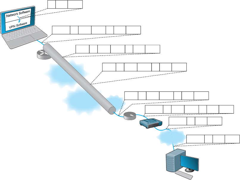
FIGURE 8.11 Using VPN Software
same way as employees physically located on the network. The user uses VPN software
on his or her computer to connect to the VPN device at the office. The VPN gateway
accepts the user’s log-in, establishes the tunnel, and the software begins forwarding
packets over the Internet. An access VPN provides a less expensive connection than
having a national toll-free phone number that connects directly into large sets of modems
at the organization’s office. Compared with a typical ISP-based remote connection, the
access VPN is a more secure connection than simply sending packets over the Internet.
Figure 8.11 shows an access VPN.
8.5.3 How VPNs Work
When packets move across the Internet, they are much like postcards in the paper mail.
Anyone can read what they contain. VPNs provide security by encapsulating (i.e., sur-
rounding) packets in a separate, secure packet that is encrypted. No one can read the
encapsulated data without knowing the password that is used to decrypt the packet.
Layer-2 and layer-3 VPNs work very similarly, except that layer-2 VPNs encapsulate
the user’s data starting with the layer-2 packet (the Ethernet frame) while layer-3 VPNs
encapsulate the user’s data starting with the layer-3 packet (the IP packet).
8.5 VIRTUAL PRIVATE NETWORKS 289
Figure 8.11 shows how a layer-3 access VPN using IPSec works. Suppose an
employee is working at home with a LAN that uses a router to connect to the Internet
via an Internet Service Provider (ISP) using DSL (we explain how DSL works in the next
chapter). When the employee wants to use the VPN, he or she starts the VPN software
on his or her computer and uses it to log-in to the VPN gateway at the office. The VPN
software creates a new “interface” on the employee’s computer that acts exactly like a
separate connection into the Internet. Interfaces are usually hardware connections, but the
VPN is a software interface, although the employee’s computer doesn’t know this—it’s
just another interface. Computers can have multiple interfaces; a laptop computer often
has two interfaces, one for Ethernet and one for wireless Wi-Fi.
The VPN gateway at the office is also as a router and a DCHP server. The VPN
gateway assigns an IP address to the VPN interface on the employee’s computer that
is an IP address in a subnet managed by the VPN gateway. For example, if the VPN
gateway has an IP address of 156.56.198.1 and managed the 156.56.198.x subnet, it
would assign an IP address in this subnet domain (e.g., 156.56.198.55).
The employee’s computer now thinks it has two connections to the Internet: The
traditional interface that has the computer’s usual IP address and the VPN interface that
has an IP address assigned by the VPN gateway. The VPN software on the employee’s
computer makes the VPN interface the default interface for all network traffic to and
from the Internet, which ensures that all messages leaving the employee’s computer flow
through the VPN interface to the VPN gateway at the office.
Suppose the employee sends an HTTP request to a Web server at the office (or
somewhere else on the Internet). The Web browser software will create an HTTP packet
that is passed to the TCP software (which adds a TCP segment), and this in turn is passed
to the IP software managing the VPN interface. The IP software creates the IP packet
using the source IP address assigned by the VPN gateway. Normally, the IP software
would then pass the IP packet to the Ethernet software that manages the Ethernet interface
into the employee’s LAN, but since the IP packet is being sent out the VPN interface, the
IP packet is passed to the VPN software managing the VPN interface. Figure 8.11 shows
the message as it leaves the network software and is passed to the VPN for transmission:
an HTTP packet, surrounded by a TCP segment, surrounded by an IP packet.
The VPN software receives the IP packet, encrypts it, and encapsulates it (and
its contents: the TCP segment, and the HTTP packet) with an Encapsulating Security
Payload (ESP) packet using IPSec encryption. The contents of the ESP packet (the IP
packet, the TCP segment, and the HTTP packet) are encrypted so that no one except
the VPN gateway at the office can read them. You can think of the IPSec packet as an
application layer packet whose destination is the office VPN gateway. How do we send
an application layer packet over the Internet? Well, we pass it to the TCP software, which
is exactly what the VPN software does.
The VPN software passes the ESP packet (and its encrypted contents) to the
employee’s computer normal Internet interface for transmission. This interface has been
sitting around waiting for transmissions, but since the VPN interface is defined as the
primary interface to use, it has received no messages to transfer except those from the
VPN software.
This interface treats the ESP packet as an application layer packet that needs to
be sent to the VPN gateway at the office. It attaches a transport layer packet (a UDP

290 CHAPTER 8 WIDE AREA NETWORKS
datagram in this case, not a TCP segment). It then passes the ESP packet to the IP
software which creates an IP packet with an IP destination address of the VPN gateway
at the office and a source IP of the employee’s computer’s normal Internet interface.
It passes this IP packet to the Ethernet software, which adds an Ethernet frame and
transmits it to the employee’s router.
The employee’s router receives the Ethernet frame, strips off the frame, and reads
the IP packet. It sees that the packet needs to be sent to the VPN gateway at the office,
which means sending the packet to the Employee’s ISP over the DSL circuit. Since DSL
uses PPP as its layer-2 protocol, it adds a PPP frame and sends the packet over the DSL
circuit to the ISP.
The router at the ISP strips off the PPP frame and reads the IP packet, which it
uses to route the packet through the Internet. As the packet moves over the Internet,
the layer-2 frame changes at each hop, depending on the circuit in use. For example,
if the ISP uses a T3 circuit, then the ISP creates an appropriate layer-2 frame to move
the packet over the T3 circuit (which usually is a PPP frame).
The packet travels from the Internet to the ISP that connects the office to the
Internet and arrives at the office’s router. This router will strip off the incoming layer-2
frame (suppose the office uses a T-3 connection with PPP as shown in the figure), read
the IP packet, and create an Ethernet frame that will send the packet to the office VPN
gateway. The VPN gateway will strip off the Ethernet frame, read the IP packet, strip it
off, read the UDP datagram, strip it off, and hand the ESP packet to its VPN software.
The VPN gateway’s software will decrypt the ESP packet, and deencapsulate the IP
packet (and the TCP segment and HTTP packet it contains) from the ESP packet. The
VPN gateway now has the IP packet (and the TCP segment and HTTP packet) that was
8.4 CISCO’S METRO ETHERNET
MANAGEMENT
FOCUS
The Cisco Systems Inc. offices in San Jose, Cal-
ifornia, used four SONET OC-3 links provided by
different common carriers. Cisco needed more
capacity, so when one of the common carriers
decided to discontinue its SONET services, Cisco
decided to try metro Ethernet.
Cisco replaced one OC-3 with a 200 Mbps
metro Ethernet circuit from AT&T. AT&T installed
two parallel 1 Gbps fiber optic circuits from the
Cisco office into the AT&T network in San Jose.
Only one circuit is in use; the other is a backup in
case the first circuit fails.
The circuit connects into the AT&T network
through an edge switch whose job is to add MPLS
tags to the incoming frames to route them through
the AT&T network to their destination. Although
the circuit is capable of supporting 1 Gbps of data,
this switch limits the circuit capacity to ensure that
the circuit does not use more than the 200 Mbps of
data that Cisco has contracted for. Cisco’s router
into the AT&T network is also configured to only
enable 200 Mps of data on this circuit. If Cisco
needs more capacity, it can change its contract
with AT&T and Cisco and AT&T will change the
capacity setting on their switch and router.
The circuit has proven to be very reliable and
now provides 200 Mbps at a lower cost than
the previous OC-3 circuit. Cisco plans to convert
the remaining OC-3 circuits to metro Ethernet
in the coming years.
SOURCE: ‘‘How Cisco Deployed a High-Speed
WAN,’’ Cisco.com.
8.5 VIRTUAL PRIVATE NETWORKS 291
8.5 ENERGY SCIENCES NETWORK
MANAGEMENT
FOCUS
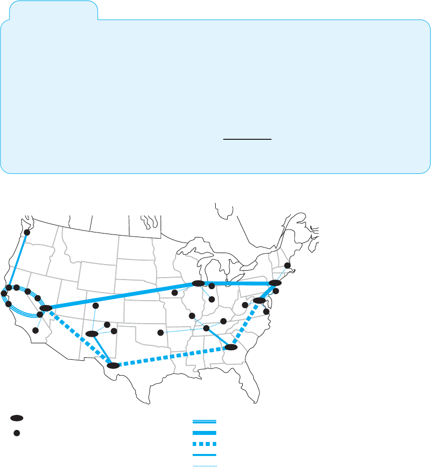
The Energy Sciences Network serves the U.S.
Department of Energy and the thousands of cor-
porate and university scientists doing research for
it. It is one of the fastest wide area networks in the
world because its users, researching high energy
physics, human genomics, and climate model-
ing, routinely move terabyte-sized files across the
network.
The current network uses a mixture of very
high speed optical Ethernet services as well as
high speed ATM, and moderate speed T3 circuits
(see Figure 8.12). The Network has always been
an early adopter of new technologies, so the San
Francisco ring, currently running at 20 Gbps, will
upgrade to 100 Gbps Ethernet within the next
2 years as it becomes available. Likewise, the
older ATM portions of the network will gradually
move to faster Ethernet services.
SOURCE: ‘‘ESnet turns to high-speed optical
MANs.’’
NetworkWorld,
May 23, 2005, p. 12.
20 Gbps Ethernet
Major Hub
Office
10 Gbps Ethernet
2.5 Gbps ATM (OC-48)
155 Mbps ATM (OC-3)
45 Mbps T3
FIGURE 8.12
Energy Sciences Network
originally created by the software on the employee’s computer. The VPN gateway reads
this IP packet and creates an Ethernet frame to send it on the next hop to its destination
and transmits it into the office network, where it ultimately reaches the Web server. On
this last leg of the journey after it leaves the VPN gateway, the packet is not encrypted
and can be read like a normal packet on the Internet.

292 CHAPTER 8 WIDE AREA NETWORKS
The return path from the Web server back to the employee’s computer is very
similar. The Web server will process the HTTP request packet and create an HTTP
response packet which it sends back to the employee’s computer. The source address
on the IP packet that the Web server received was the IP address associated with the
VPN interface on the employee’s computer, so the Web server uses this address as the
destination IP address. This packet is therefore routed back to the VPN gateway, because
the subnet for this IP address is defined as being in the subnet that the VPN gateway
manages. Once again, the return packet is not encrypted on this part of the journey.
When the packet arrives at the VPN gateway, it looks up the VPN IP address in
its table and sees the usual IP address of the computer associated with that VPN address.
The VPN gateway creates an ESP packet and encrypts the IP packet from the Web server
(and the TCP segment and HTTP packet it contains). It then treats the ESP packet as
a application layer packet that needs to be sent to the VPN software on the employee’s
computer; it passes it to its TCP software for a UDP datagram, then to its IP software for
an IP packet, and then to its Ethernet software for an Ethernet frame and transmission
back through the VPN tunnel.
When the packet eventually reaches the employee’s computer, it comes in the
normal Internet interface and eventually reaches the TCP software that strips off the
UDP datagram. The TCP software sees that the ESP packet inside the UDP datagram is
destined for the VPN software (remember that TCP port numbers are used to identify to
which application layer software a packet should go). The VPN software removes the
ESP packet and passes the IP packet it contains to the IP software, which in turn strips
off the IP packet, and passes the TCP segment it contains to the TCP software, which
strips off the TCP segments and passes the HTTP packet it contains to the Web browser.
8.6 THE BEST PRACTICE WAN DESIGN
Developing best practice recommendations for WAN design is more difficult than for
LANs and backbones because the network designer is buying services from different
companies rather than buying products. The relatively stable environment enjoyed by the
WA N common carriers is facing sharp challenges by VPNs at the low end and Ethernet
and MPLS services at the high end. As larger IT and equipment firms begin to enter the
VPN and Ethernet services markets, we should see some major changes in the industry
and in the available services and costs.
We also need to point out that the technologies in this chapter are primarily used
to connect different corporate locations. Technologies primarily used for Internet access
(e.g., DSL, cable modem) are discussed in the next chapter.
We use the same two factors as we have previously for LANs and backbones (effec-
tive data rates and cost), plus add one additional factor: network integration, which refers
to the ease with which the WAN service can be used to connect LANs and backbones.
Figure 8.13 summarizes the major services available today for the WAN, grouped
by the type of service. A few patterns should emerge from the table. For small WANs
with low data transmission needs, VPN services are a reasonable alternative, provided
the lack of reliability is not a major issue. Otherwise, frame relay is a good choice. See
Figure 8.14.

8.6 THE BEST PRACTICE WAN DESIGN 293
Type of Service
Circuit-Switched Services
POTS
ISDN
Dedicated-Circuit Services
T Carrier
SONET
Packet-Switched Services
ATM
Frame Relay
Ethernet
33.6 Kbps to 56 Kbps
128 Kbps to 1.5 Mbps
64 Kbps to 274 Mbps
50 Mbps to 10 Gbps
52 Mbps to 10 Gbps
56 Kbps to 45 Mbps
1 Mbps to 40 Gbps
Low
Moderate
Moderate
High
High
Moderate
Moderate
Difficult
Difficult
Moderate
Moderate
Moderate
Moderate
Simple
Nominal
Data Rates
Relative
Cost
Network
Integration
MPLS
VPN Services
VPN
64 kbps to 155 Mbps
56 Kbps to 40 Gbps
Moderate
Low
Moderate
Moderate
FIGURE 8.13 WAN services
For networks with moderate data transmission needs (64 Kbps–2 Mbps) there are
several distinct choices. If cost is more important than reliability, then a VPN is probably
a good choice. If you need flexibility in the location of your network connections and
you are not completely sure of the volume of traffic you will have between locations,
frame relay or MPLS are good choices. If you have a mature network with predictable
demands, then T carrier services is probably a good choice or MPLS.
For high-traffic networks (2 Mbps–45 Mbps), the new Ethernet or MPLS services
are a dominant choice. Some organizations may prefer the more mature—and therefore
proven—T3 or frame relay services, depending on whether the greater flexibility of
packet services provides value or a dedicated circuit makes more sense.
Network Needs
Low Traffic Needs
(64 Kbps or less)
VPN if reliability is less important
Frame relay otherwise
Moderate Traffic Needs
(64 Kbps to 2 Mbps)
VPN if reliability is less important
T1 or fractional T1 if network volume is stable and predictable
Frame relay or MPLS otherwise
High Traffic Needs
(2 Mbps to 45 Mbps)
Ethernet or MPLS if available
T3 if network volume is stable and predictable
Frame relay otherwise
Very High Traffic Needs
(45 Mbps to 10 Gbps)
Ethernet or MPLS if available
SONET if network volume is stable and predictable
ATM otherwise
Recommendation
FIGURE 8.14 Best practice WAN recommendations

294 CHAPTER 8 WIDE AREA NETWORKS
For very-high-traffic networks (45 Mbps–10 Gbps), Ethernet or MPLS services
again are a dominant choice. And again some organizations may prefer the more mature
ATM or SONET services, depending on whether the greater flexibility of packet services
provides value or a dedicated circuit makes more sense.
Unless their data needs are stable, network managers often start with more flexible
packet-switched services and move to the usually cheaper dedicated-circuit services once
their needs have become clear and an investment in dedicated services is safer. Some
packet-switched services even permit organizations to establish circuits with a zero-CIR
(and rely entirely on the availability of the MAR) so network managers can track their
needs and lease only what they need.
Network managers often add a packet network service as an overlay network on
top of a network built with dedicated circuits to handle peak data needs; data usually
travels over the dedicated-circuit network, but when it becomes overloaded with traffic,
the extra traffic is routed to the packet network.
8.7 IMPROVING WAN PERFORMANCE
Improving the performance of WANs is handled in the same way as improving LAN
performance. You begin by checking the devices in the network, by upgrading the circuits
between the computers, and by changing the demand placed on the network (Figure 8.15).
8.7.1 Improving Device Performance
In some cases, the key bottleneck in the network is not the circuits; it is the devices that
provide access to the circuits (e.g., routers). One way to improve network performance is
to upgrade the devices and computers that connect backbones to the WAN. Most devices
are rated for their speed in converting input packets to output packets (called latency).
Not all devices are created equal; some vendors produce devices with lower latencies
than others.
Performance Checklist
Increase Computer and Device Performance
• Upgrade devices
• Change to a more appropriate routing protocol (either stati c or dynamic)
Increase Circuit Capacity
• Analyze message traffic and upgrade to faster circuits where needed
• Check error rates
Reduce Network Demand
• Change user behavior
• Analyze network needs of all new systems
• Move data closer to users
FIGURE 8.15 Improving performance of metropolitan and local area networks