FitzGerald J., Dennis A., Durcikova A. Business Data Communications and Networking
Подождите немного. Документ загружается.


7.3 BACKBONE NETWORK ARCHITECTURES 255
7.2 VLANs IN SHANGRI-LA
MANAGEMENT
FOCUS
Shangri-La’s Rasa Sayang Resort and Spa is a
5-star luxury resort hotel located on the scenic
Batu Feringgi Beach in Penang, Malaysia. The
resort has two main buildings, the 189-room Gar-
den Wing and the 115-room Rasa Wing, with
additional 11 private spa villas.
Over the years, the resort had installed three
separate networks: one for the resort’s opera-
tions, one for its POS (point-of-sales) system, and
one for Internet access for guests (which was
wired, not wireless). The networks were separate
to ensure security, so that users of one network
could not gain access to another.
As part of multimillion dollar renovation, the
resort decided to upgrade its network to gigabit
speeds and to offer wireless Internet access to
its guests. Rather than build three separate net-
works again, it decided to build one network using
VLANs. The resort installed 12 wireless access
points and 24 VLAN switches, plus two larger
core VLAN switches. The VLAN architecture pro-
vides seamless management of the wired and
wireless components as one integrated network,
and ensures robust performance and security.
SOURCE: Source: ‘‘Wireless Access Amidst Lush
Greenery of Penang Shangri-La’s Resort,’’ HP
ProCurve Customer Case Study, Hewlett-Packard,
2010.
switches] would ignore QoS information.) With the Ethernet packet’s ability to carry
VLAN information that includes priorities, we now have QoS capabilities in the data
link layer. This means we can connect VOIP telephones directly into a VLAN switch
and configure the switch to reserve sufficient network capacity so that they will always
be able to send and receive voice messages.
The biggest drawbacks to VLANs are their cost and management complexity.
VLAN switches also are much newer technologies that have only recently been stan-
dardized. Such “leading-edge” technologies sometimes introduce other problems that
disappear only after the specific products have matured.
How VLANs Work VLANs work somewhat differently than the traditional
Ethernet/IP approach described in the previous chapters. Each computer is assigned
into a specific VLAN that has a VLAN ID number (which ranges from 1 to 1005 or
to 4094 depending on whether the extended range standard is used). Each VLAN ID
is matched to a traditional IP subnet, so each computer connected to a VLAN switch
also receives a traditional IP address assigned by the VLAN switch (the switch acts as
a DHCP server; see Chapter 5). Most VLAN switches can support only 255 separate
VLANs simultaneously, which means each switch can support up to 255 separate IP
subnets, which is far larger than most organizations want in any single device.
Computers are assigned into the VLAN (and the matching IP subnet) based on the
physical port on the switch into which they are connected.
2
Don’t confuse the physical
port on the switch (which is the jack the cable plugs into) with the TCP port number
from Chapter 5; they are different—it’s another example of networking using the same
2
One type of VLAN switches used to enable computers to be assigned into VLANs is based on dynamic
criteria such as their Ethernet address, but this type of switch has essentially disappeared. The extra cost of
dynamic VLAN switches outweighed the benefits they provided and they lost in the marketplace.
256 CHAPTER 7 BACKBONE NETWORKS
word (“port”) to mean two different things. The network manager uses software to assign
the computers to specific VLANs using their physical port numbers so it is simple to
move a computer from one VLAN to another.
When a computer transmits an Ethernet frame, it uses the traditional Ethernet and
IP addresses we discussed in previous chapters (e.g., Chapters 4 and 5) to move the
frame through the network because it doesn’t know that it is attached to a VLAN switch.
Recall that as a message moves through the network, the IP address is used to specify
the final destination and the Ethernet address is used to move the message from one
computer to the next along the route to the final destination. Some devices, such as
layer-2 switches, are transparent; the Ethernet frame passes through them unchanged.
Other devices, such as routers, remove the Ethernet frame and create a new Ethernet
frame to send the message to the next computer. VLANs are transparent—although they
do change the frame at times.
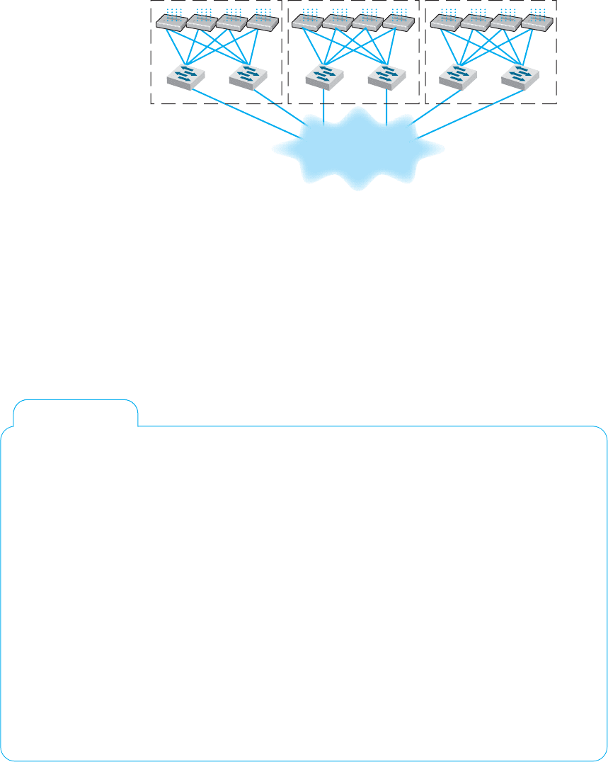
Let’s use Figure 7.13 to explain how VLAN switches work. We’ll assume this
network uses the first three bytes to specify the IP subnet. In this example, we have
three VLAN switches with three IP subnets (179.58.10.x, 179.58.3.x, and 179.58.11.x)
and three VLANs (10, 20, 30). A router is used to enable communication among the
different IP subnets.
Suppose a computer connected to switch 2 (IP 179.58.10.102) sends a message to
a c omputer on the same IP subnet that is also connected to switch 2 (IP 179.58.10.103).
The sending computer will recognize that the destination computer is in the same IP
subnet, create an Ethernet frame with the destination computer’s Ethernet address (using
ARP if needed to find the Ethernet address), and transmit the frame to VLAN switch
2. When a VLAN switch receives a frame that is destined for another computer in the
same subnet on the same VLAN switch, the switch acts as a traditional layer-2 switch:
it forwards the frame unchanged to the correct computer. Remember from Chapter 6
that switches build a forwarding table that lists the Ethernet address of every computer
connected to the switch. When a frame arrives at the switch, the switch looks up the
Ethernet address in the forwarding table, and if it finds the address, then it forwards the
frame to the correct computer. We discuss what happens if the Ethernet address is not
in the forwarding table in a moment.
Suppose that a computer wants to send a message to a computer in the same subnet,
but that the destination computer is actually on a different VLAN switch. For example
in Figure 7.13, suppose this same computer (IP 179.58.10.102) sends a message to a
computer on switch 3 (179.58.10.50). The sending computer will act exactly the same
because to it, the situation is the same. It doesn’t know where the destination computers
is; it just knows that the destination is on its own subnet. The sending computer will
create an Ethernet frame with the destination computer’s Ethernet address (using ARP if
needed to find the Ethernet address) and transmit the frame to VLAN switch 2. Switch
2 receives the frame, looks up the destination Ethernet address in its forwarding table,
and recognizes that the frame needs to go to switch 3.
Virtual LAN switches use Ethernet 802.1q tagging to move frames from one switch
to another. Chapter 4 showed that the layout of an Ethernet frame contains a VLAN tag
field which VLAN switches use to move frames among switches. When a VLAN switch
receives an Ethernet frame that needs to go to a computer on another VLAN switch, it
changes the Ethernet frame by inserting the VLAN ID number and a priority code into the
VLAN tag field. When a switch is configured, the network administrator defines which
7.3 BACKBONE NETWORK ARCHITECTURES 257
VLANs span which switches and also defines VLAN trunks—circuits that connect two
VLAN switches and enables traffic to flow from one switch to another. As a switch
builds its forwarding table, it receives information from other switches and inserts the
Ethernet addresses of computers attached to them into its forwarding table along with
the correct trunk to use to send frames to them.
In this case, switch 2 receives the frame, and uses the forwarding table to identify
that it needs to send the frame over the trunk to switch 3. It changes the frame by inserting
the VLAN ID and priority code into the tag field and transmits the frame over the trunk
to switch 3. Switch 3 receives the frame, looks the Ethernet address up in its forwarding
table, and identifies the specific computer the frame needs to be sent to. The switch
removes the VLAN tag information and transmits the revised frame to the destination
computer. In this way, neither the sending computer nor the destination computer are
aware that the VLAN exists. The VLAN is transparent.
Suppose the same sending computer (179.58.10.102) wants to send a message to a
computer on a different subnet in the same VLAN (e.g., 179.58.7.30 on the same switch
or 179.58.11.20 on switch 3). The sending computer recognizes that the destination is
on a different subnet, and therefore creates an Ethernet frame with a destination Ethernet
address of its router (179.58.10.1), and sends the frame to switch 2.
At this point, everything works the same as in the previous example. Switch 2 looks
up the destination Ethernet address in its forwarding table, and recognizes that the frame
needs to go to switch 1 because the router’s Ethernet address is listed in the forwarding
table as being reachable through switch 1. Switch 2 sets the VLAN tag information and
sends the frame over the trunk to switch 1. Switch 1 looks up the destination Ethernet
address in its forwarding table, and sees that the router is attached to it. Switch 2 removes
the VLAN tag field and sends the frame to the router.
The router is a layer-3 device, so when it receives the message, it strips off the
Ethernet frame and reads the IP packet. It looks in its routing table and sees that the
destination IP address is within a subnet it controls (either 179.58.7.x or 179.58.11.x
depending on which destination computer the packet was sent to). The router creates a
new Ethernet frame and sets the destination Ethernet address to the destination computer
(using an ARP if needed) and sends the frame to switch 1.
Switch 1 reads the Ethernet address and looks it up in its forwarding table. It discovers
the frame needs to go to switch 2 (for 179.58.7.30) or switch 3 (for 179.58.11.20), sets the
VLAN tag field, and forwards the frame over the trunk to the correct switch. This switch
in turn removes the VLAN tag information and sends the frame to the correct computer.
Until now, we’ve been talking about unicast messages—messages from one com-
puter to another—that are the majority of network traffic. However, what about broadcast
messages such as ARPs that are sent to all computers in the same subnet? Each com-
puter on a VLAN switch is assigned into a subnet with a matching VLAN ID. When
a computer issues a broadcast message, the switch identifies the VLAN ID of the sending
computer and then sends the frame to all other computers that have the same VLAN ID.
These computers may be on the same switch, or on different switches. For example, sup-
pose computer 179.58.10.102 issues an ARP to find an Ethernet address (e.g., the router’s
address). Switch 2 would send the broadcast frame to all attached computers with the
same VLAN ID (e.g., 179.58.10.103). Switch 2’s trunking information also tells it than
VLAN 10 spans switch 1 and switch 3, so it sends the frame to them. They, in turn,
use their tables to send it to their attached computers that are in the same VLAN (which

258 CHAPTER 7 BACKBONE NETWORKS
includes the router). Note that the router has multiple IP addresses and VLAN IDs because
it is connected to several different VLANs and subnets (three, in our example here).
We have also assumed that the VLAN switch has a complete forwarding table—a
table that lists all the Ethernet addresses of all the computers in the network. Just like
a layer-2 switch, the VLAN switch learns Ethernet addresses as it sends and receives
messages. Where the VLAN switch is first turned on, the forwarding table is empty, just
like the forwarding table of a layer-2 switch; however, its VLAN ID and trunk tables are
complete because these are defined by the network administrator. Suppose the switch has
just been turned on and has an empty forwarding table. It receives an Ethernet frame,
looks up the destination address in the forwarding table, and does not find where to send
it. What happens?
If the VLAN switch were a layer-2 switch, it would send the frame to all ports.
However, a VLAN switch can be a bit smarter than this. If you think about how IP
works, you will see that an Ethernet frame is always sent to a computer in the same IP
subnet as the sending computer. Any time a frame needs to move to a different subnet, it
goes through a router which sits on both subnets. Think about it for a minute before you
continue reading. Therefore, any time the VLAN switch can’t find a destination Ethernet
address in the forwarding table, it treats the frame as a broadcast frame and sends it to
all the computers in the same subnet, which in VLAN terms means all the computers
with the same VLAN ID.
This means that a VLAN architecture can improve performance by reducing traffic
in the network compared with a switched backbone architecture. Since a switched back-
bone uses layer-2 switches, all the computers are in the same subnet, and all broadcast
traffic goes to all computers. By using a VLAN we can limit where broadcast traffic
flows by dividing the network into separate subnets, so that broadcast messages only go
to computers in the same subnet.
7.4 THE BEST PRACTICE BACKBONE DESIGN
The past few years have seen radical changes in the backbone, both in terms of new tech-
nologies (e.g., gigabit Ethernet) and in architectures (e.g., switched backbones, VLANs).
Fifteen years ago, the most common backbone architecture was the routed backbone,
connected to a series of shared 10Base-T hubs in the LAN.
Today, the most effective architecture for the distribution layer in terms of cost
and performance is a switched backbone (either rack-mounted or using a chassis switch)
because it provides the best performance at the least cost. For the core layer, most
organizations use a routed backbone. Many large organizations are now implementing
VLANs, especially those which have departments spread over multiple buildings, but
VLANs add considerable cost and complexity to the network.
Given the trade-offs in costs, there are several best practice recommendations. First,
the best practice architecture is a switched backbone or VLAN for the distribution layer
and a routed backbone for the core layer. Second, the best practice recommendation
for backbone technology is gigabit Ethernet. Considering the LAN and backbone envi-
ronments together, the ideal network design is likely to be a mix of layer-2 and layer-3
7.4 THE BEST PRACTICE BACKBONE DESIGN 259
Distribution
Access
Layer-2 or
Layer-3
Switch
Layer-2
Switch
Building Building Building
Core
Layer-3 Switching
FIGURE 7.14 The best practice network design
Ethernet switches. Figure 7.14 shows one likely design. The access layer (i.e., the LANs)
uses 100Base-T layer-2 Ethernet switches running on cat 5e or cat 6 twisted-pair cables
to provide flexibility for 100Base-T or 1000Base-T. The distribution layer uses layer-2
or layer-3 Ethernet switches that use 100Base-T or more likely 1000Base-T/F (over fiber
or cat 6) to connect to the access layer. To provide good reliability, some organizations
may provide redundant switches, so if one fails, the backbone continues to operate. The
core layer uses layer-3 Ethernet switches running 10 GbE or 40 GbE over fiber.
7.1 MULTIPROTOCOL LABEL SWITCHING
TECHNICAL
FOCUS
Multiprotocol Label Switching (MPLS) is an
approach to improving QoS and the movement
of packets with different layer-2 protocols through
TCP/IP networks.
With MPLS, routers called Label Switched
Routers (LSRs) are used. The network manager
defines a series of Forwarding Equivalence Classes
(FEC) through the network of LSRs. Each FEC has a
reserved data rate and a QoS.
When a packet arrives at the edge of the MPLS
network, an edge LSR reads the destination address
on the incoming packet. The edge LSR can be con-
figured to use the IP address, the IP address and the
source or destination port, or the address in any pro-
tocol understood by the LSR. The edge LSR accepts
the incoming packet and attaches an MPLS
label
(a
packet that contains the FEC address). The edge LSR
then forwards the packet to the next LSR as defined
in the FEC.
This LSR reads the MPLS label and removes it
from the incoming packet, consults its MPLS address
table to find the packet’s next destination, attaches
a new MPLS label with the new FEC address, and
forwards the packet to the next LSR in the FEC.
This process continues until the packet reaches
the edge LSR closest to its final destination. This
edge LSR strips off the MPLS label and forwards
the packet outside of the MPLS network in exactly
the same format in which it entered the MPLS
network.
The advantage of MPLS is that it can easily inte-
grate layer-2 protocols and also provide QoS in an IP
environment. It also enables traffic management by
enabling the network manager to specify FEC based
on both the IP address and the source or destination
port.

260 CHAPTER 7 BACKBONE NETWORKS
7.5 IMPROVING BACKBONE PERFORMANCE
The method for improving the performance of BNs is similar to that for improving
LAN performance. First, find the bottleneck, then solve it (or, more accurately, move
the bottleneck somewhere else). You can improve the performance of the network by
improving the performance of the computers and other devices in the network, by upgrad-
ing the circuits between computers, and by changing the demand placed on the network
(Figure 7.15).
7.5.1 Improving Computer and Device Performance
The primary functions of computers and devices in BNs are routing and protocol transla-
tions. If the devices and computers are the bottleneck, routing can be improved with faster
devices or a faster routing protocol. Distance vector routing is faster than dynamic routing
(see Chapter 5) but obviously can impair circuit performance in high-traffic situations.
Link state routing is usually used in WANs and MANs because there are many possible
routes through the network. BNs often have only a few routes through the network, so
link state routing may not be too helpful since it will delay processing and increase the
network traffic because of the status reports sent through the network. Distance vector
routing will often simplify processing and improve performance.
Most backbone devices are store-and-forward devices. One simple way to improve
performance is to ensure that they have sufficient memory. If they don’t, the devices will
lose packets, requiring them to be retransmitted.
7.5.2 Improving Circuit Capacity
If network circuits are the bottlenecks, there are several options. One is to increase overall
circuit capacity (e.g., by going from 100Base-T Ethernet to gigabit Ethernet). Another
option is to add additional circuits alongside heavily used ones so that there are several
circuits between some devices.
Performance Checklist
Increase Computer and Device Performance
• Change to a more appropriate routing protocol (either distance vector or link state)
• Buy devices and software from one vendor
• Increase the devices' memory
Increase Circuit Capacity
• Upgrade to a faster circuit
• Add circuits
Reduce Network Demand
• Change user behavior
• Reduce broadcast messages
FIGURE 7.15
Improving backbone
network performance

7.6 IMPLICATIONS FOR MANAGEMENT 261
In many cases, the bottleneck on the circuit is only in one place—the circuit to the
server. A switched network that provides 100 Mbps to the client computers but a faster
circuit to the server (e.g., 1000Base-T) can improve performance at very little cost.
7.5.3 Reducing Network Demand
One way to reduce network demand is to restrict applications that use a lot of network
capacity, such as desktop videoconferencing, medical imaging, or multimedia. In practice,
it is often difficult to restrict users. Nonetheless, finding one application that places a
large demand on the network and moving it can have a significant impact.
Much network demand is caused by broadcast messages, such as those used to
find data link layer addresses (see Chapter 5). Some application software packages and
NOS modules written for use on LANs also use broadcast messages to send status
information to all computers on the LAN. For example, broadcast messages inform users
when printers are out of paper, or when the server is running low on disk space. When
used in a LAN, such messages place little extra demand on the network because every
computer on the LAN gets every message.
This is not the case for routed backbones because messages do not normally flow
to all computers, but broadcast messages can consume a fair amount of network capacity
in switched backbones. In many cases, broadcast messages have little value outside their
individual LAN. Therefore, some switches and routers can be set to filter broadcast
messages so that they do not go to other networks. This reduces network traffic and
improves performance.
7.6 IMPLICATIONS FOR MANAGEMENT
As the technologies used in LANS and WLANs become faster and better, the amount
of traffic the backbone network needs to support is increasing at an even faster rate.
Coupled with the significant changes in the best practice recommendations for the design
of backbone networks, this means that many organizations have had to replace their
backbones completely. We would like to think that these have been one-time expenditures,
but, as traffic grows, demand placed on the backbone will continue to increase meaning
the amount spent on switches and routers for use in the backbone will increase. Designing
backbone networks to be easily upgradable is now an important management goal.
As recently as five years ago, ATM was seen as a viable technology for use in
backbone networks (ATM is discussed in the next chapter). Today, however, it is clear
that Ethernet has beaten ATM as the best backbone technology and ATM is now a
legacy backbone technology: no new backbone networks will be installed using it and
most vendors have stopped the development of ATM for backbone networks.
As Ethernet moves more extensively into the backbone, the costs associated with
buying and maintaining backbone devices and training networking staff will decrease,
since now there will be one standard technology in use throughout the LAN, WLAN,
and backbone. The new focus is on faster and faster versions of Ethernet. While we will
spend more on new equipment, performance will increase much more quickly, and the
cost to operate the equipment will decrease.

262 CHAPTER 7 BACKBONE NETWORKS
SUMMARY
Network Components There are two basic components to a BN: the network cable and the
hardware devices that connect other networks to the backbone. The cable is essentially the same as
those used in LANs, except that it is usually fiber optic to provide higher data rates. The hardware
devices include routers, gateways, and switches. Switches connect two LAN segments that use the
same data link and network protocol and forward only those messages that need to go to other
network segments. Routers connect two or more LANs that use the same or different data link
protocols but employ the same network protocol. Gateways connect two or more LANs that use the
same or different data link and network protocols (usually different). Layer-2 switches are similar
to bridges, whereas layer-3 switches are similar t o routers.
Backbone Architectures Network designers often think about three distinct technology layers
when designing backbones. The access layer is the LAN, the distribution layer connects the LANs
together, and the core layer connects the distribution-layer BNs together. The distribution layer
is usually a backbone within a building, whereas the core layer often connects buildings and is
sometimes called the campus network. A routed backbone uses a set of routers or layer-3 switches
to connect LANs together and moves messages using layer-3 addresses. A switched backbone
uses one device, usually a layer-2 switch, to connect the LANs. A VLAN uses layer-2 or layer-3
switches to build logical or virtual LANs that enable the network manager to assign capacity
separate from physical location.
Best Practice Backbone Design The best practice backbone architecture for most organizations
is a switched backbone (using a rack or a chassis switch) or VLAN in the distribution layer and a
routed backbone in the core layer. The recommended technology is gigabit Ethernet.
Improving Backbone Performance Backbone performance can be improved by choosing the best
network layer routing protocols. Upgrading to faster circuits and adding additional circuits on very
busy backbones can also improve performance. Finally, one could move servers closer to the end
users or reduce broadcast traffic to reduce backbone traffic.
KEY TERMS
access layer
backbone network (BN)
campus network
chassis switch
core layer
distribution layer
enterprise network
forwarding equivalence
class (FEC)
gateways
IEEE 802.1q
label switched router
(LSR)
layer-2 switch
layer-3 switch
main distribution facility
(MDF)
module
multiprotocol label
switching (MPLS)
multiswitch VLAN
patch cables
rack
routed backbone
router
single-switch VLAN
switched backbone
virtual LAN (VLAN)
VLAN ID
VLAN tag
VLAN trunk
QUESTIONS
1. Compare and contrast switches, routers,
and gateways.
2. How does a layer-2 switch differ from
a layer-3 switch?
3. How does a router differ from a layer-3 switch?
4. Under what circumstances would you
want to use a router?

EXERCISES 263
5. What is an enterprise network?
6. What are the three technology layers impor-
tant in backbone design?
7. Explain how routed backbones work.
8. Where are routed backbones most
commonly used?
9. Explain how switched backbones work.
10. What are the key advantages and disadvantages
of routed and switched backbones?
11. Compare and contrast rack-based and
chassis-based switched backbones.
12. What is a module and why are mod-
ules important?
13. Explain how single-switch VLANs work.
14. Explain how multiswitch VLANs work.
15. What is IEEE 802.1q?
16. What are the advantages and disad-
vantages of VLANs?
17. How can you improve the performance of a BN?
18. Why are broadcast messages important?
19. What are the preferred architectures used in the
technology layers in backbone design?
20. Some experts are predicting that Ethernet will
move into the WAN. What do you think?
EXERCISES
7-1. Survey the BNs used in your organization. Do they
use Ethernet or some other technology? Why?
7-2. Document one BN in detail. What devices are
attached, what cabling is used, and what is the topol-
ogy? What networks does the backbone connect?
7-3. You have been hired by a small company to install
a backbone to connect four 100base-T Ethernet
LANs (each using one 24-port hub) and to pro-
vide a connection to the Internet. Develop a sim-
ple backbone and determine the total cost (i.e.,
select the backbone technology and price it, select
the cabling and price it, select the devices and
price them, and so on). Prices are available at
www.datacommwarehouse.com, but use any source
that is convenient. For simplicity, assume that cat-
egory 5, category 5e, category 6, and fiber-optic
cable have a fixed cost per circuit to buy and install,
regardless of distance, of $50, $60, $120, and $300,
respectively.
MINI-CASES
I. Pat’s Engineering Works
Pat’s Engineering Works is a small company that specializes in complex engineering consulting projects. The
projects typically involve one or two engineers who do data intensive analyses for companies. Because so much
data are needed, the projects are stored on the company’s high-capacity server but moved to the engineers’
workstations for analysis. The company is moving into new offices and wants you to design its network. It has
a staff of 8 engineers (which is expected to grow to 12 over the next 5 years), plus another 8 management and
clerical employees who also need network connections but whose needs are less intense. Design the network.
Be sure to include a diagram.
II. Hospitality Hotel
Hospitality Hotel is a luxury hotel whose guests are mostly business travelers. To improve its quality of service,
it has decided to install network connections in each of its 600 guest rooms and 12 conference meeting rooms.
Last year, the hotel upgraded its own internal networks to switched 100Base-T, but it wants to keep the public
network (i.e., the guest and meeting rooms) separate from its private network (i.e., its own computer systems).
Your task is to design the public network and decide how to connect the two networks together. Be sure to
include a diagram.
264 CHAPTER 7 BACKBONE NETWORKS
III. Indiana University
Reread Management Focus 7.1. What other alternatives do you think that Indiana University considered? Why
do you think they did what they did?
IV. Shangi-La
Reread Management Focus 7.2. What other alternatives do you think that the Shangri-La Resort considered?
Why do you think they did what they did?
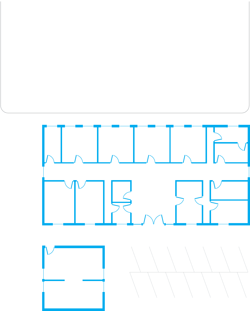
V. Western Trucking
Western Trucking operates a large fleet of trucks that deliver shipments for commercial shippers such as
food stores, retailers, and wholesalers. Their main headquarters building and secondary building are shown in
Figure 7.16. They currently have a mix of shared 10base-T and switched 10base-T LANs, connected by a
series of switches. They want to upgrade to a faster network. Design a new network for them, including the
architecture and specific backbone and LAN technologies to be used.
Data
Processing
Accounts
Payable
and Payroll
Accounts
Receivable
Sales and
Marketing
Security
President's
office
Conference
room
Intrastate
Operations
Interstate
Operations
Agent
operations
Customer
Service
Mail
room
Human
Resources
Information
Services
Fleet Maintenance
Dispatch
Lobby
and
reception
Main building
Secondary building
Parking lot
FIGURE 7.16 Facility map of the Western Trucking headquarters