Hussian Z., AbdullahM.Z., AlimuddinZ. Basic Fluid Mechanics and Hydraulic Machines
Подождите немного. Документ загружается.

90
Basic Fluids Mechanics and Hydraulic Machines
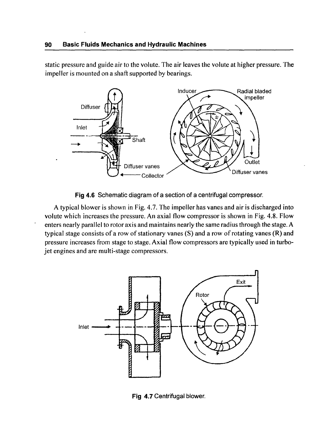
static pressure and guide air to the volute. The air leaves the volute at higher pressure. The
impeller is
mOllnted on a shaft supported by bearings.
Diffuser
Inlet
<f---Collector
Fig
4.6 Schematic diagram
of
a section
of
a centrifugal compressor.
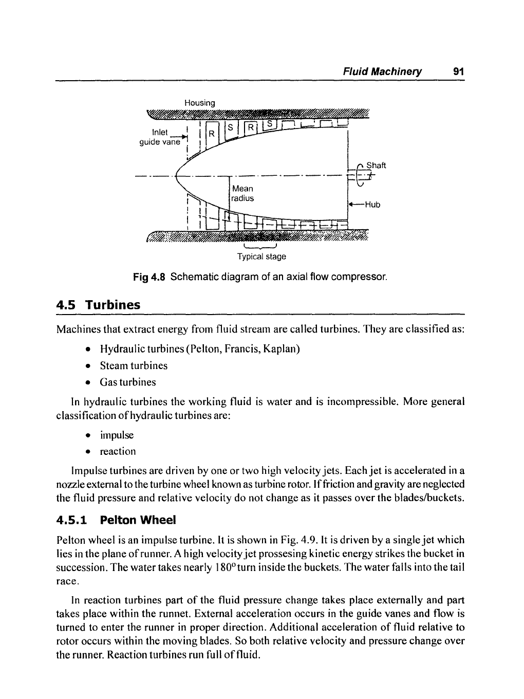
A typical blower is shown
in
Fig. 4.7. The impeller has vanes and air is discharged into
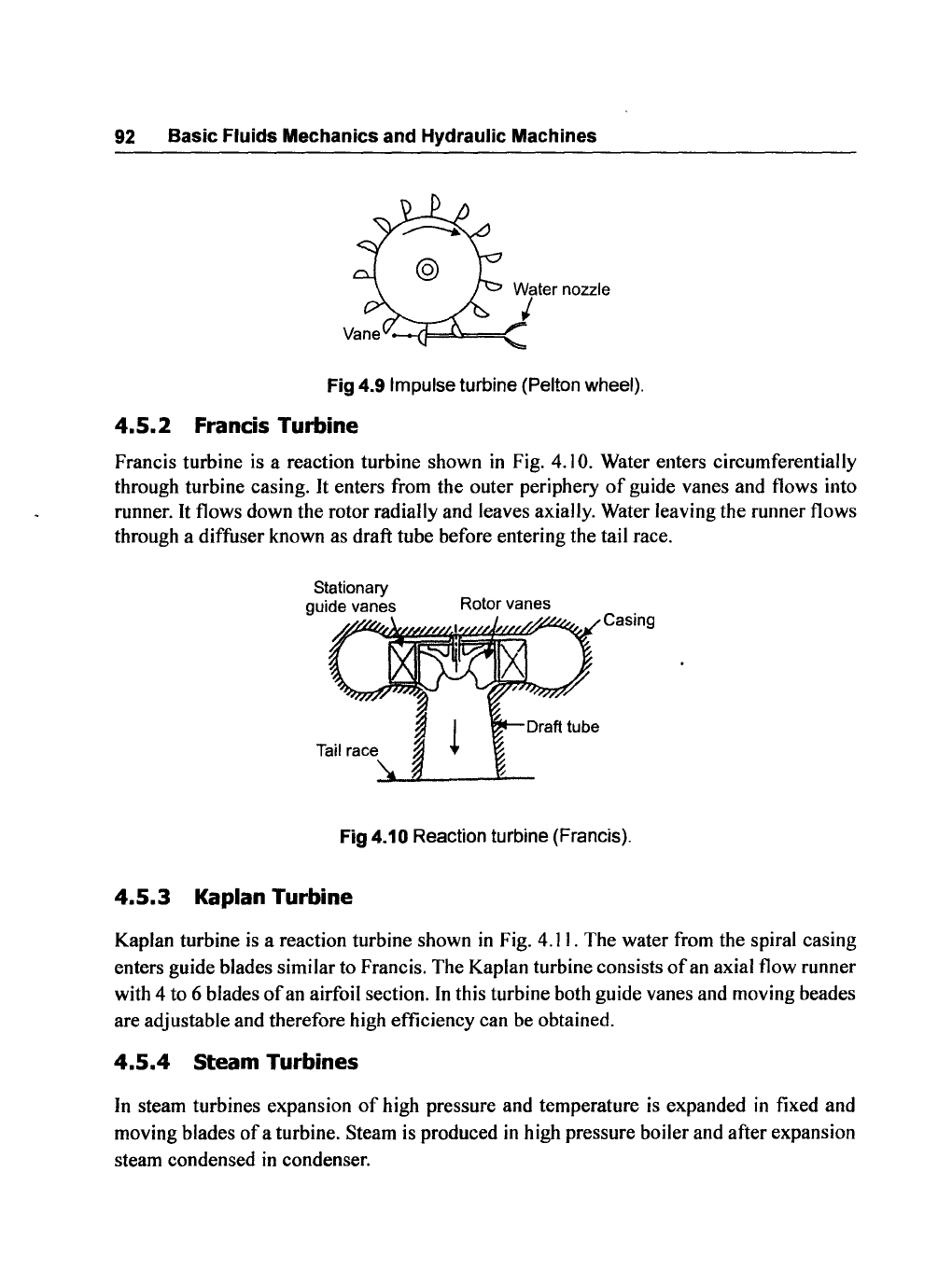
volute which increases the pressure. An axial flow compressor is shown
in
Fig. 4.8. Flow
enters nearly parallel to rotor axis and maintains nearly the same radius through the stage. A
typical stage consists
of
a row
of
stationary vanes (S) and a row
of
rotating vanes (R) and
pressure increases from stage to stage. Axial flow compressors are typically used in turbo-
jet
engines and are multi-stage compressors.
Inlet
---..
Fig 4.7 Centrifugal blower.
Inlet I
guide
var;e+1
~
Typical stage
Fluid Machinery
91
Fig 4.8 Schematic diagram
of
an
axial flow compressor.
4.5 Turbines
Machines that extract energy from fluid stream are called turbines.
They
are classified as:
• Hydraulic turbines (Pelton, Francis, Kaplan)
• Steam turbines
• Gas turbines
In
hydraulic turbines the working fluid
is
water and is incompressible. More general
classification
of
hydraulic turbines are:
• impulse
• reaction
Impulse turbines are driven by one or two high velocity jets. Each
jet
is
accelerated
in
a
nozzle external to the turbine wheel known as turbine rotor.
Iffriction and gravity are neglected
the fluid pressure and relative velocity do not change as it passes over the blades/buckets.
4.5.1
Pelton Wheel
Pelton wheel
is
an impulse turbine.
It
is shown
in
Fig. 4.9.
It
is driven by a
singlejet
which
lies
in
the plane
of
runner. A high velocity
jet
prossesing kinetic energy strikes the bucket
in
succession.
The
water takes nearly I 80° turn inside the buckets.
The
water falls into the tail
race.
In
reaction turbines part
of
the fluid pressure change takes place externally and part
takes place within the runnet. External acceleration occurs
in
the guide vanes and flow is
turned to enter the runner
in
proper direction. Additional acceleration
of
fluid relative to
rotor occurs within the moving blades. So both relative velocity and pressure change over
the runner. Reaction turbines run full
offluid.
92
Basic Fluids Mechanics and Hydraulic Machines
Fig
4.9 Impulse turbine (Pelton wheel).
4.5.2
Francis Turbine
Francis turbine is a reaction turbine shown
in
Fig. 4.10. Water enters circumferentially
through turbine casing.
It
enters from the outer periphery
of
guide vanes and flows into
runner.
It
flows down the rotor radially and leaves axially. Water leaving the runner flows
through a diffuser known as draft tube before entering the tail race.
Rotor vanes
Stationary
guide vanes
A-~~~~i~~f-'r
Casing
Fig 4.10 Reaction turbine (Francis).
4.5.3
Kaplan Turbine
Kaplan turbine
is
a reaction turbine shown
in
Fig. 4.11. The water from the spiral casing
enters guide blades similar to Francis. The Kaplan turbine consists
of
an axial flow runner
with 4 to 6 blades
of
an airfoil section.
In
this turbine both guide vanes and moving beades
are adjustable and therefore high efficiency can be obtained.
4.5.4
Steam Turbines
In
steam turbines expansion
of
high pressure and temperature
is
expanded
in
fixed and
moving blades
of
a turbine. Steam is produced
in
high pressure boiler and after expansion
steam condensed
in
condenser.
4.5.5
Gas
Turbine
/
Guide
. blades
Fig
4.11
Reaction turbine (Kaplan).
Fluid Machinery 93
In
gas turbine expansion
of
high pressure and temperature
of
gas is expanded
in
fixed and
moving blades
of
turbine. The exhaust gases after expansion go into the atmosphere.
4.6
Euler's Theory Applied
to
Turbo Machines
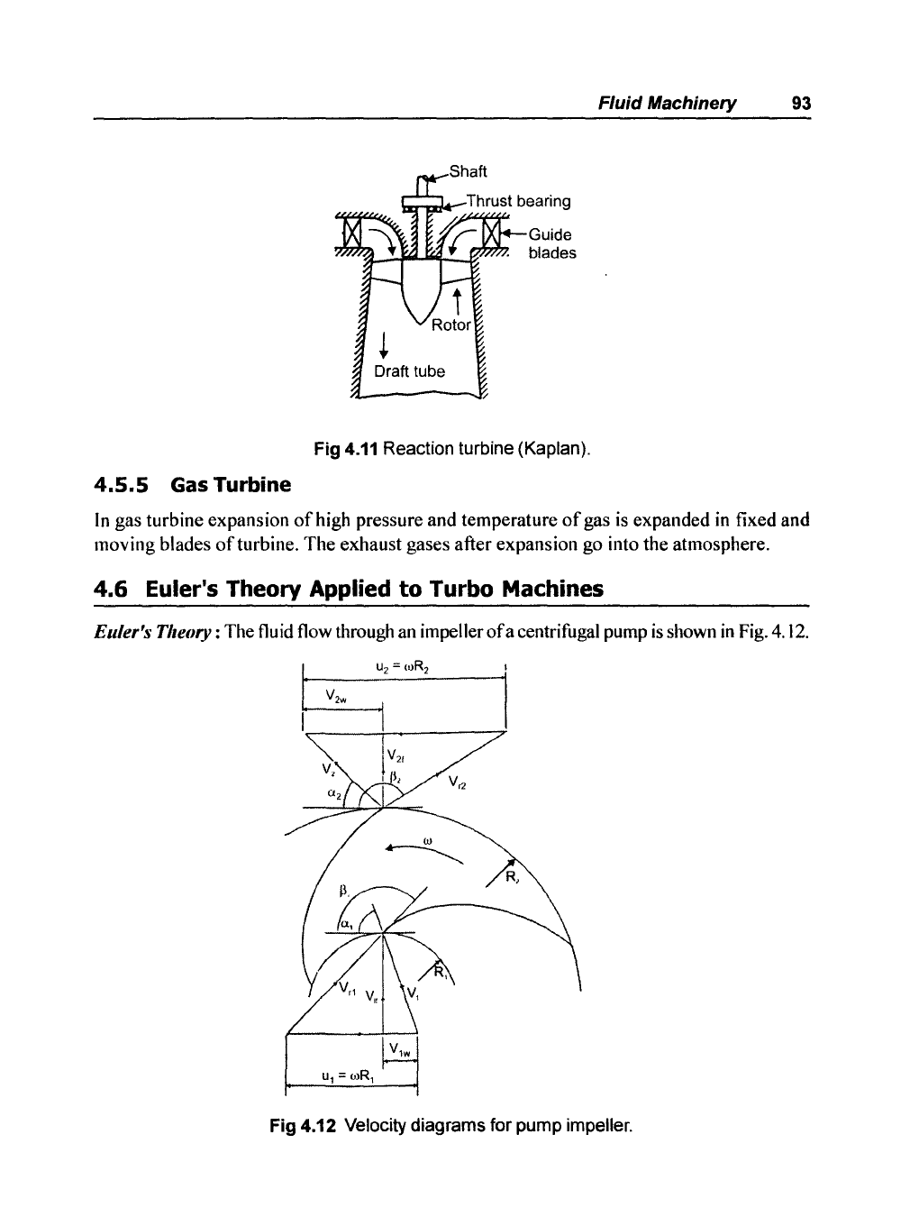
Ellier's Theory: The fluid flow through an impellerofacentrifugal pump
is
shown
in
Fig. 4.12.
R,
Fig 4.12 Velocity diagrams for pump impeller.
94 Basic Fluids Mechanics and Hydraulic Machines
According to Euler's theory torque applied on the impeller
is
the rate
of
change
of
angular
momentum
ofthe
fluid passing through the impeller. The following assumptions are made.
• The velocity
of
water is uniform at inlet and exit
of
the impeller.
• The relative velocities at inlet and exit are tangential to inlet and exit tips
ofthe
vanes.
Fig
4.12 shows only two vanes
of
the impeller, let
V I - absolute velocity
of
the impeller entering the impeller
at
radius
RI
V 2 - absolute velocity
offluid
leaving the impeller at radium
R2
V rI and V
r2
are relative velocities at inlet and exit, u I and u
2
tangential velocities at inlet
and exit.
a
I and a
2
inlet and exit angles
of
V I and V 2
13
1
and
13
2
vane tip angles at inlet and exit..
The angles are measured from the forward directed tangents so that both angles
13
1
and
13
2
are
greater
than 90°.
The
angular
velocity
co
is
connected to tangential velocities
u
l
and u
2
.
. .... (4.1)
..... (4.2)
According to assumptions made previously V
rl
and V
r2
are tangents to the vane tips
at
inlet and exit.
The velocity
V I is vector sum
ofV
rl
and u
l
at inlet and velocity V 2 is vector sum
ofV
r2
and u
2
at
exit
of
vane. Resolve the absolute velocities V I and V 2 into,tangential and radial
components as velocity
of
whirl and velocity
of
flow,
we
have
Velocity
of
whirl
at
inlet = V
lw
= VI
cosa
l
Velocity
of
whirl at exit = V
2w
= V 2
cosa
2
Velocity
of
flow at inlet = V
lf
=
Vlsina
l
Velocity
of
flow at exit = V
2f
= V 2sina2
The
volume
flow rate
may
be
expressed
in
the
form
of
flow
component
and
flow
area
A either at inlet
or
exit given by
Q =
AI
V
lf
=
A2
V
2f
If
the width
of
impeller
at
inlet and exit
is
b
l
and
b
2
respectively,
we
have
AI
;=
nO
I
b
l
A2
=
n0
2
b
2
..... (4.3)
..... (4.4)
..... (4.5)
where
0,
and
02
are impeller diameters at inlet and exit
The
flow rate Q
is
then given by
Q =
1t0,b,V
If
=
1t
02
b
2
V2f
Also mass flow rate is given by
~
= pQ,
where p is density
offluid
Fluid Machinery 95
o
Rate
of
angular momentum
MI
of
impeller being the product
of
mean flow rate
~,
whirl componant V
wi
and radius R,.
Rate
of
change
of
angular
moment
is
equal to applied torque
T
=
~
V
2w
R2
-
~
V
Iw
RI
The
power
input to drive this torque is given by
P =
T.O)
P =
~0)(V2W
R2
- V\w R
I
)
P =
~
(u
2
V
2w
- u, V
lw
)
4.6.1
Euler's Head
. .... (4.7)
..... (4.8)
..... (4.9)
If
the whole
of
mechanical power is converted into hydraulic power then total head H would
be given by the relation
P=yQH
where Q is flow rate and y sp. weight
of
the fluid.
Equating eqs.
(4.9) (4.10)
we
get,
or
~----------------~
H =
(U
2
V
2w
-U1V
1w
)
g
E=
(U
2
V
2W
-u1V)w)
g
..... (4.10)
..... (4.11)
96
Basic Fluids Mechanics and Hydraulic Machines
This is called Euler's head
of
the pump.
The
head available is actually less than Euler's
head.
If
the water enters the impeller without whirl such that V
Iw
= 0 then Euler's equation
is
written as
IE
=
u,
~'w
..... (4.12)
4.6.2
Euler's Equation in the Kinetic Form
It
is
useful to express Euler's head
in
terms
of
their absolute velocities rather than their
components. From the velocity triangles
of
Fig 4.12,
we
have
V
Iw
= V
Icosal
and
V
2w
= V 2
cosa
2
Using cosine rule, we have
so that
Vr~
=
V,2
+
u~
-2u
1
V
Icosal
V
r
2
2
=
vi
+ u
~
- 2u
2
V 2cos
a
2
u
2
cosa
2
=
2"
(u~
+
Vi
-
Vr~)
Substituting
in
equation (4.11)
E=
V
2
_ v
2
2
I +
+
2
V2
Vrl
-
r2
2g 2g
II
III
..... (4.13)
In
this expression the first term I denotes the increase
of
kinetic head
of
fluid
in
the
impeller
due
to change in absolute velocities.
The
second term
II
represents energy used in
setting fluid into circular motion about impeller axis.
The
third term
III
is to regain static
head
due
to reduction
in
relative velocity.
From the mode
of
derivation it is clear
that
Euler's equation is applicable to a pump and
also to a turbine. However, the equation would change its sign. Thus
u,V,w
-U
2
V
2
W
(Turbine)
E=
g
E=
u
2
V2w
-
U,
V'W
(Pump)
g
For axial flow machines u\ = u
2
= u and
E =
U(Vlw
- V
2
J
g
E =
U(V2w
- V
1w
)
g
Fluid Machinery
97
(Turbine)
(Pump)

"This page is Intentionally Left Blank"

CHAPTER
- 5
Pelton
Turbine
One
of
the
two
260
MW
Pelton turbines in the Sellerin-Sitz power station, Austria.
The operating head
is
1233 m.
Courtesy:
Sulzer Ester Wyss, Zurich, Switzerland.