Hussian Z., AbdullahM.Z., AlimuddinZ. Basic Fluid Mechanics and Hydraulic Machines
Подождите немного. Документ загружается.


"This page is Intentionally Left Blank"
Pelton Turbine
101
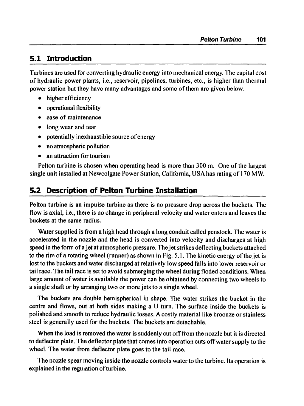
5.1 Introduction
Turbines are used for converting hydraulic
enelb'Y
into mechanical energy. The capital cost
of
hydraulic power plants, i.e., reservoir, pipelines, turbines, etc.,
is
higher than thermal
power station but they have many
advantag~s
and some
of
them are given below.
• higher efficiency
• opemtional tlexibility
• ease
of
maintenance
• long wear and tear
• potentially inexhaustible source
of
energy
• no atmospheric pollution
• an attraction for tourism
Pelton turbine
is
chosen when operating head
is
more than 300
m.
One
of
the largest
single unit installed at Newcolgate
Power Station, California, USA has rating
of
170
MW.
5.2 Description
of
Pelton Turbine Installation
Pelton turbine
is
an impulse turbine as there
is
no pressure drop across the buckets. The
tlow
is
axial, i.e., there
is
no change
in
peripheral velocity and water enters and leaves the
buckets at the same radius.
Water supplied is from a high head through a long conduit called penstock. The water
is
accelerated
in
the nozzle and the head
is
converted into velocity and discharges at high
speed
in
the form
of
a
jet
at atmospheric pressure. The
jet
strikes detlecting buckets attached
to the rim
of
a rotating wheel (runner) as shown
in
Fig. 5.1. The kinetic energy
of
the
jet
is
lost to the buckets and water discharged at relatively low speed falls into lower reservoir or
tail race. The tail race
is
set to avoid submerging the wheel during tloded conditions. When
large amount
of
water is available the power can be obtained
by
connecting two wheels to
a single shaft
or
by arranging two
or
more
jets
to a single wheel.
The buckets are double hemispherical
in
shape. The water strikes the bucket
in
the
centre and tlows, out at both sides making a
U tum. The surface inside the buckets
is
polished and smooth to reduce hydraulic losses. A costly material like broonze
or
stainless
steel
is generally used for the buckets. The buckets are detachable.
When the load
is
removed the water
is
suddenly cut
off
from the nozzle but it is directed
to deflector plate. The deflector plate that comes into operation cuts
off
water supply to the
wheel. The water from deflector plate goes to the tail race.
The nozzle spear moving inside the nozzle controls water to the turbine.
Its operation
is
explained
in
the regulation
of
turbine.
102 Basic Fluids Mechanics and Hydraulic Machines
Impeller (runner)
Spea(
Spear rod
h
D"ectO,;rA-----D-is-c-ha-r=g-e--~ra==::c'="e
_>m.
Inlet
plate
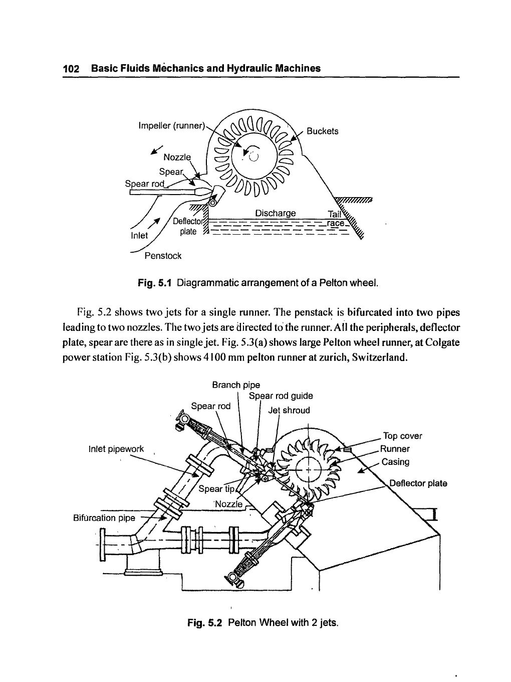
Fig.
5.1
Diagrammatic arrangement
of
a Pelton wheel.
Fig. 5.2 shows two
jets
for a single runner. The
penstac~
is bifurcated into two pipes
leading to two nozzles. The two
jets
are directed to'the runner. All the peripherals, deflector
plate, spear are there as
in
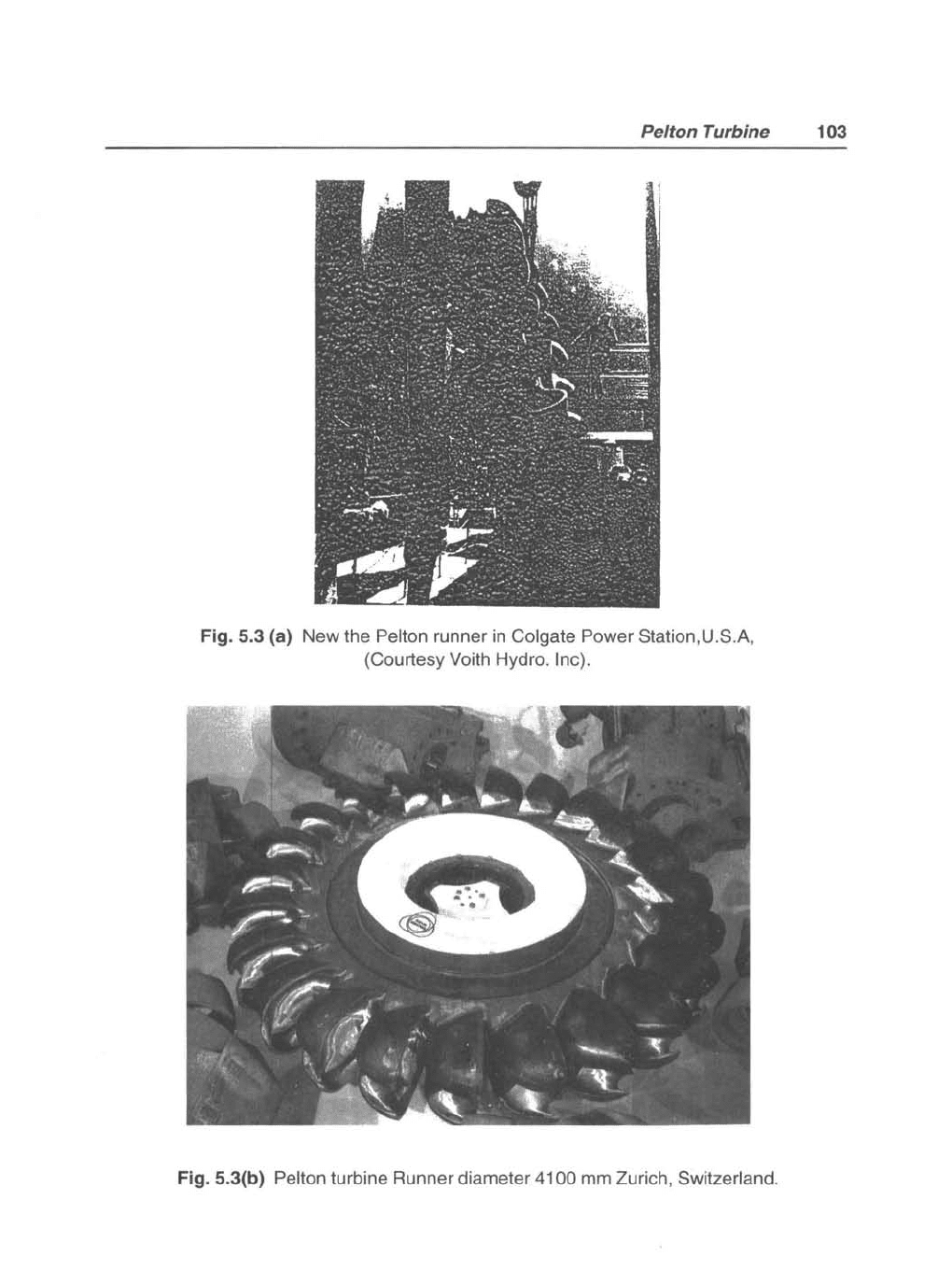
single jet. Fig. 5.3(a) shows large Pelton wheel runner, at Colgate
power station Fig. 5 .3(b) shows
4100
mm
pelton runner at zurich, Switzerland.
Branch pipe
Fig. 5.2 Pelton Wheel with 2 jets.
Pelton Turbine 103
Fig. 5.3 (a) New the Pelton runner
in
Colgate Power Station,U.S.A,
(Courtesy
Voith Hydro. Inc).
Fig. 5.3(b) Pelton turbine Runner diameter
41
00 mm Zurich, Switzerland.
104 Basic Fluids Mechanics and Hydraulic Machines
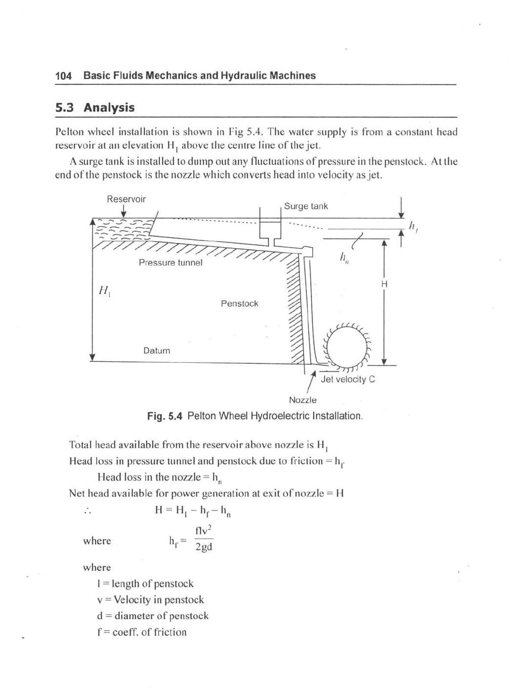
5.3 Analysis
Pelton wheel installation
is
shown
in
Fig 5.4.
The
water
supply
is
from a
constant
head
reservoir
at
an elevation H I
above
the
centre
I ine
of
the
jet.
A surge tank
is
installed to
dump
out
any fluctuations
of
pres
sure
in
the
penstock. At the
end
of
the penstock is the nozzle which converts head into velocity
asjet.
Reservoir
..
Surge tank
I
(
h"
Penstock
Dal"m 0
~--------------"~!LhJet
velocity C
Nozzle
Fig. 5.4 Pelton Wheel Hydroelectric Installation.
Total head
available
from the
reservoir
above
nozzle is
HI
Head loss in pressure tunnel
and
penstock
due
to friction =
hI'
Head loss in
the
nozzle = h
n
Net
head
available
for
power
generation
at
exit
of
nozzle = H
H=HI
-
hr-h
n
flv
2
where
h =
r
2gd
where
I = length
of
penstock
v = Velocity in penstock
d =
diameter
of
penstock
f = coeff.
of
friction
H
Pelton
Turbine
105
In practice the penstock is usually sized so that at rated power the net head is usually
85-95%
of
the total head. The net head is taken to calculate hydraulic efficiency
of
turbine.
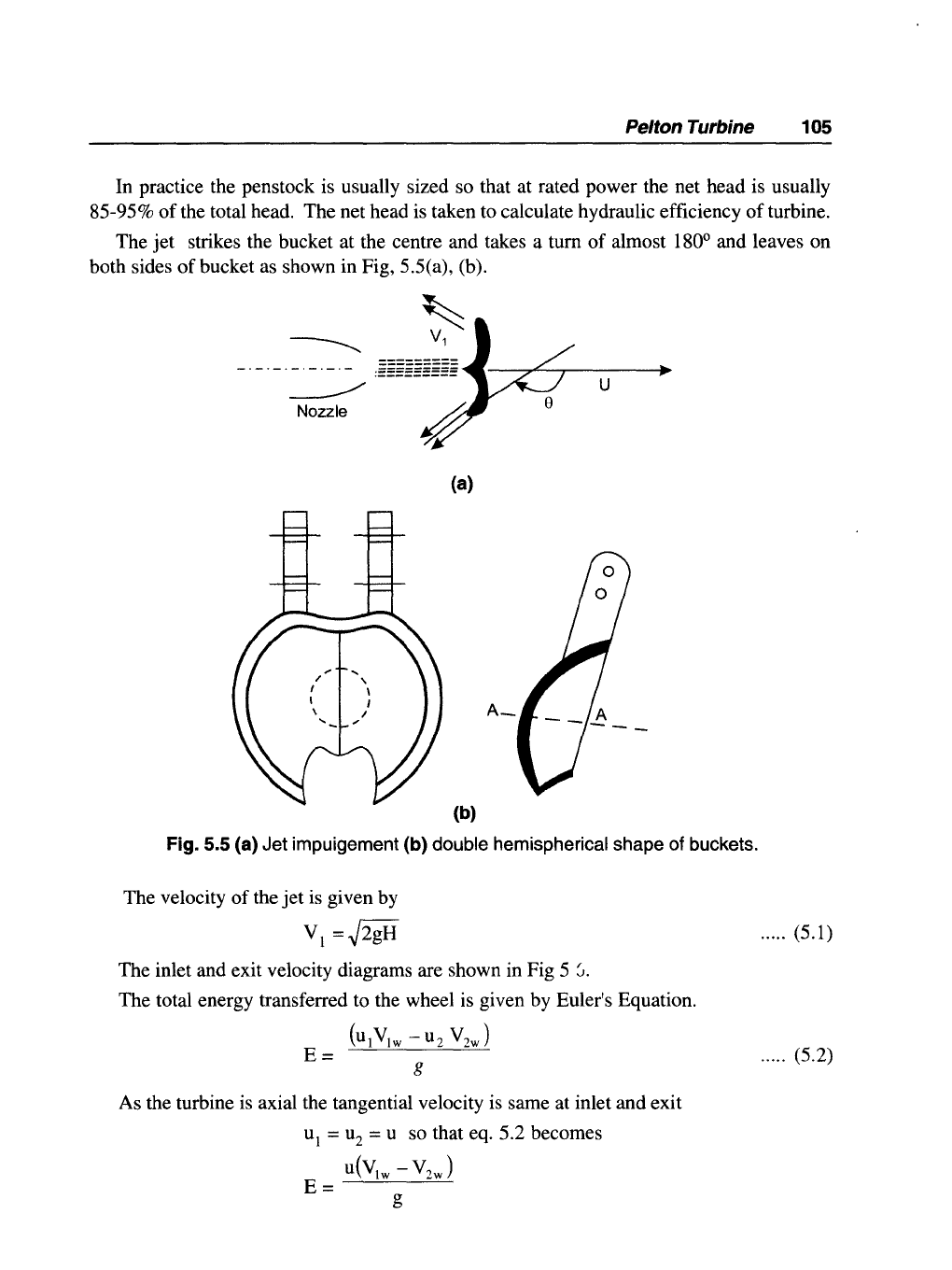
The
jet
strikes the bucket at the centre and takes a tum
of
almost 180
0
and leaves on
both sides
of
bucket as shown in Fig, 5 .5( a), (b).
~
1
u
(a)
(b)
Fig. 5.5 (a) Jet impuigement (b) double hemispherical shape of buckets.
The velocity
of
the
jet
is given by
VI
=~2gH
The inlet and exit velocity diagrams are shown in Fig 5
J.
The total energy transferred to the wheel is given by Euler's Equation.
(U1V
1W
- u
2
V
2w
)
g
As the turbine is axial the tangential velocity is same at inlet and exit
u
l
= u
2
= U so that eq. 5.2 becomes
E=
U(VIW
- V
2w
)
g
..... (5.1)
..... (5.2)
106 Basic Fluids Mechanics and Hydraulic Machines
f~"""""",,,,,,,
t
r--
--+-'U-
V1
-.LT---.v,".;
Inlet triangle
I')
Bucke'
:
,/
-----z-..,----
7
Exit triangle
rr-H
L-u
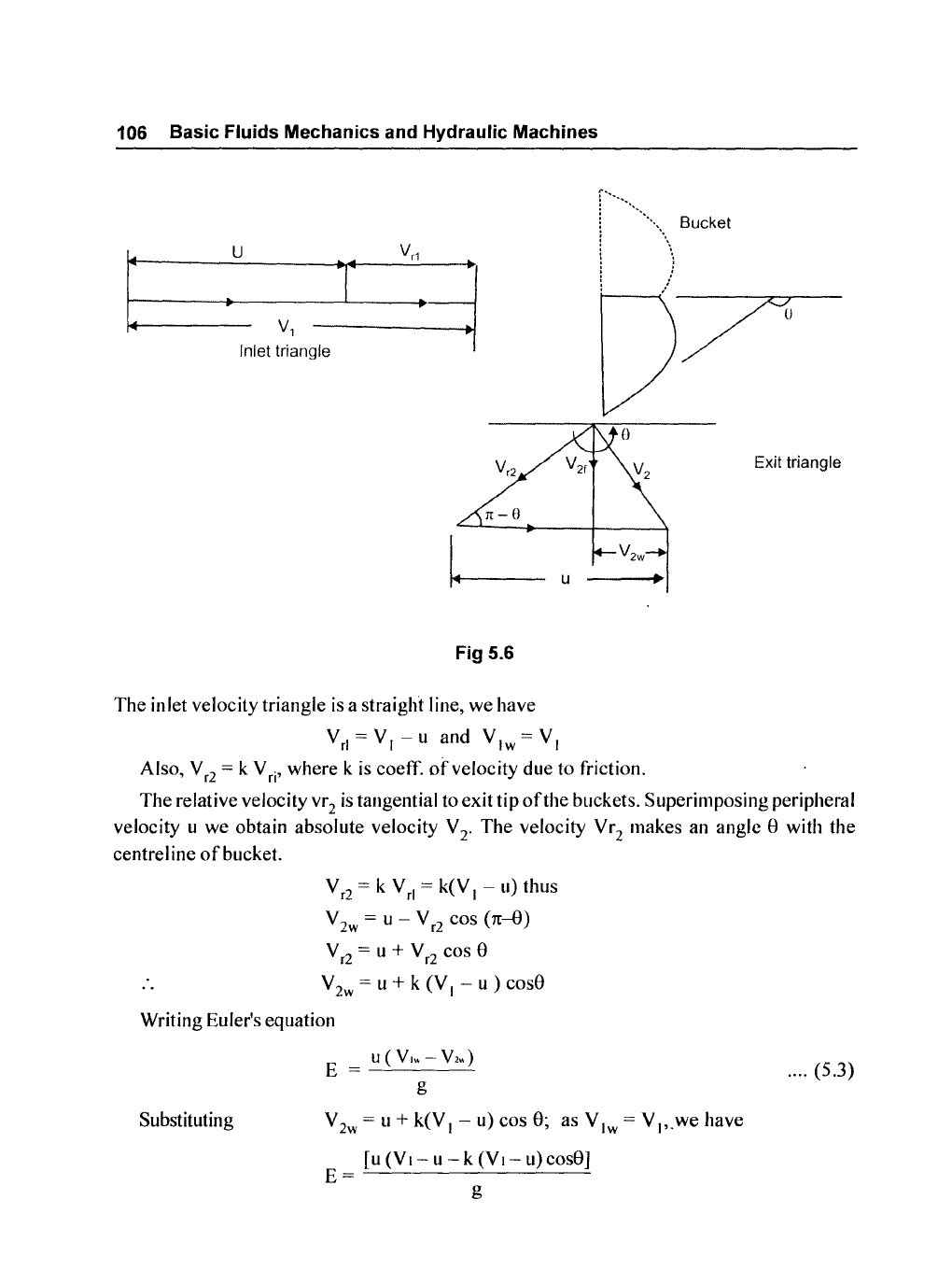
Fig 5.6
The
inlet velocity triangle
is
a straight line, we have
V rl = V I - u and V I w = V I
Also, V
r2
= k V
ri
, where k
is
coeff. ot-velocity due to friction.
The
relative velocity vr 2
is
tangential to exit tip
of
the buckets. Superimposing peripheral
velocity u we obtain absolute velocity
V 2. The velocity
Vr
2
makes an angle 8 with the
centrel ine
of
bucket.
V
r2
= k V
ri
= k(V
I
- u) thus
V
2w
= u - V
r2
cos
(1£-8)
V
r2
= U + V
r2
cos 8
V
2w
= U + k (V I - U ) cos8
Writing Euler's equation
Substituting
E
U(V,"-V2.)
g
V
2w
=
1I
+ k(V I - u) cos
8;
as V Iw =
V".we
have
[u
(Vl-
U - k
(VI-1I)cos8]
E=
g
.... (5.3)
Pelton Turbine
107
E=
(~l
[VI-u-k(VI-u)cosS]
IE=
~
[(V1-U)(I-kCOSS]1
..... (5.4)
The equation shows that there
is
no energy transfer when the bucket velocity u is either
zero
or
equal to
jet
velocity V
I.
It
is reasonable to expect therefore the maximum energy
transfer will occur at some intermediate velocity
of
the bucket velocity.
Thus differentiating
E with respect to u and equating to zero for maximum energy transfer
dE
(1- kcosSXV
I
- 2u)
=0
du g
(l-kcosS)
Hence,
VI
- 2u = 0 as cannot be zero
g
we have
Thus tangential velocity is
half
the
jet
velocity for maximum energy transfer.
Substituting this value
in
eq 5.4
Emax
=
(~~
1 (VI -
~I)
(1-
k cos S)
Emax
=
(~~
1
(1
- k cos S)
Inlet kinetic energy
to
the
jet
=
V~
Thus maximum theoretical hydraulic efficiency
of
Pelton wheel,
E
TJ
max
= K.E
of
jet
(1-
kcosS)
TJ
max
=
2g
..... (5.6)
108
Basic
Fluids
Mechanics
and
Hydraulic
Machines
In
an ideal case when e = 180, k = I;
11max
= 100%.
In
practice friction exists and K
value
is
in
the region
of
0.85 - 0.9 and also the value
of
e = 165
0
to avoid interference
u u
between incoming and outgoingjets. Therefore V is always less than 0.5. For - = 0.46
I VI
and e =
165
0
,
the maximum efficiency is around
90%
. Rewriting equation 5.4,
E
=
~
(Y
I
-
u)
(I
- kcos e) and also
K.E
of
jet
=
Y~
and
hydraulic
efficiency as
(~/~)(YI
-U )(l-kcose)
11=
Y
2 "
I I
/2g
..... (5.7)
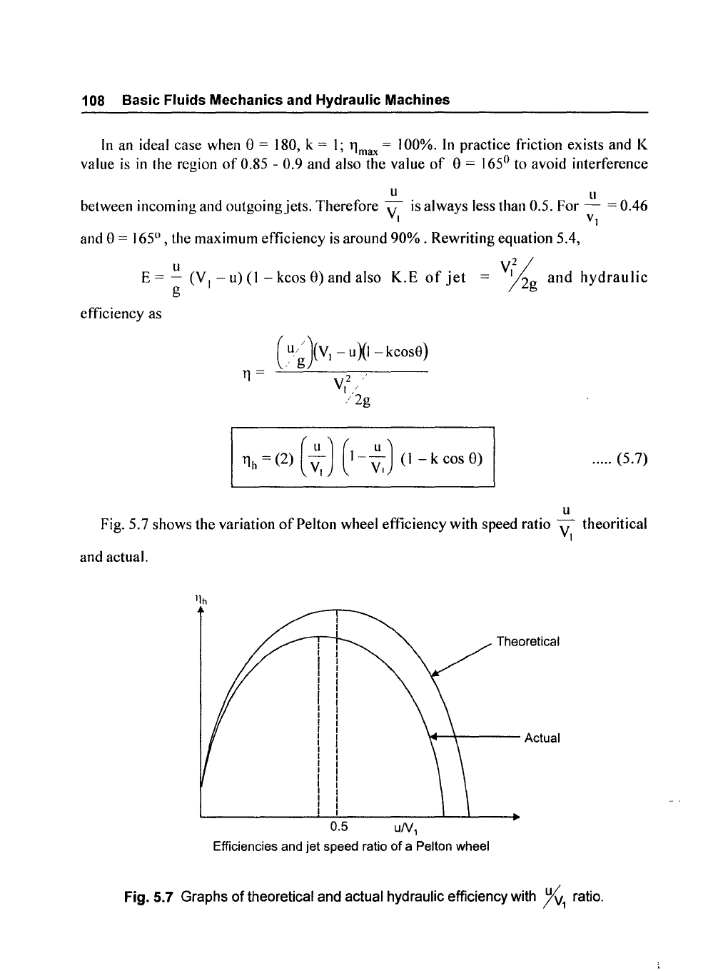
u
Fig. 5.7 shows the variation
of
Pelton wheel efficiency with speed ratio V theoritical
I
and actual.
Theoretical
\+--+----
Actual
0.5
uN
1
Efficiencies and jet speed ratio
of
a Pelton wheel
Fig. 5.7 Graphs
of
theoretical and actual hydraulic efficiency with
%1
ratio.
Pelton Turbine 109
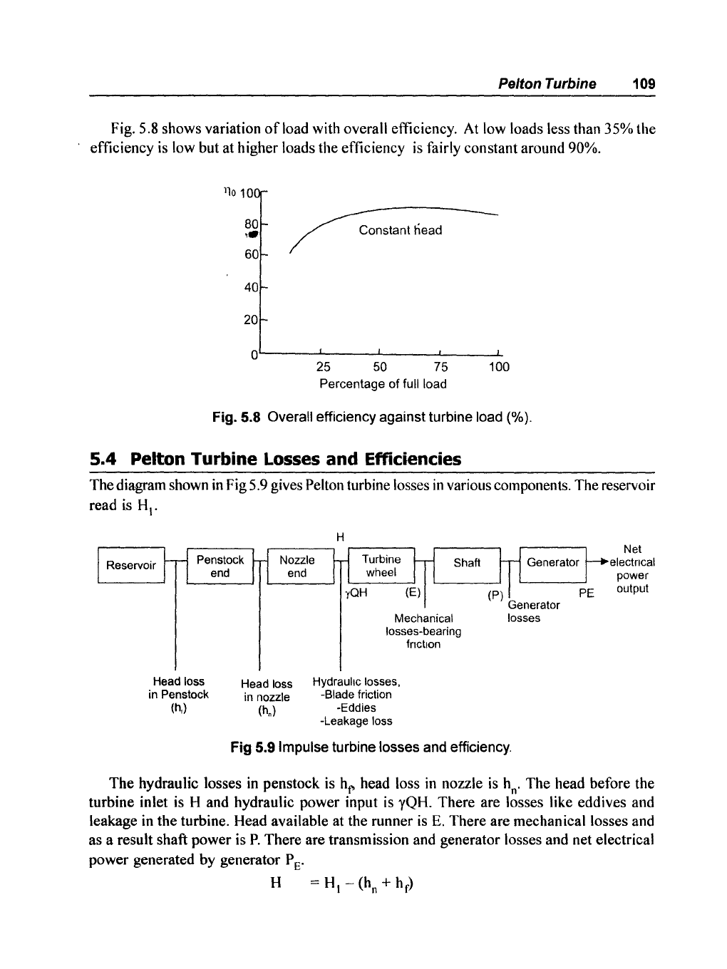
Fig. 5.8 shows variation
ofload
with overall efficiency.
At
low loads less than 35% the
efficiency
is
low but at higher loads the efficiency
is
fairly constant around 90%.
11010
80
,.
Constant head
60
40
20
O~----~-----L----~--
__
--L
25
50 75
100
Percentage of full load
Fig. 5.8 Overall efficiency against turbine load (%).
5.4 Pelton Turbine
Losses
and Efficiencies
The diagram shown
in
Fig 5.9 gives Pelton turbine losses
in
various components. The reservoir
read
is
HI'
Head loss
in Penstock
(h,)
Head loss
in nozzle
(h,)
H
Mechanical losses
losses-bearing
Hydraulic losses,
-Blade friction
-Eddies
-Leakage loss
fnctlon
Fig 5.9 Impulse turbine losses and efficiency.
Net
electncal
power
output
The hydraulic losses
in
penstock is
ht~
head loss
in
nozzle
is
h
n
.
The head before the
turbine inlet
is
H and hydraulic power input is yQH. There are losses like eddives and
leakage
in
the turbine. Head available at the runner
is
E.
There are mechanical losses and
as a result shaft power is
P.
There are transmission and generator losses and net electrical
power generated by generator
P E'
H
==
H -
(h
+
h)
I n f